Arduino Alarm System with Motion Detection Using E18-D80NK
Arduino Alarm System with Motion Detection Using E18-D80NK
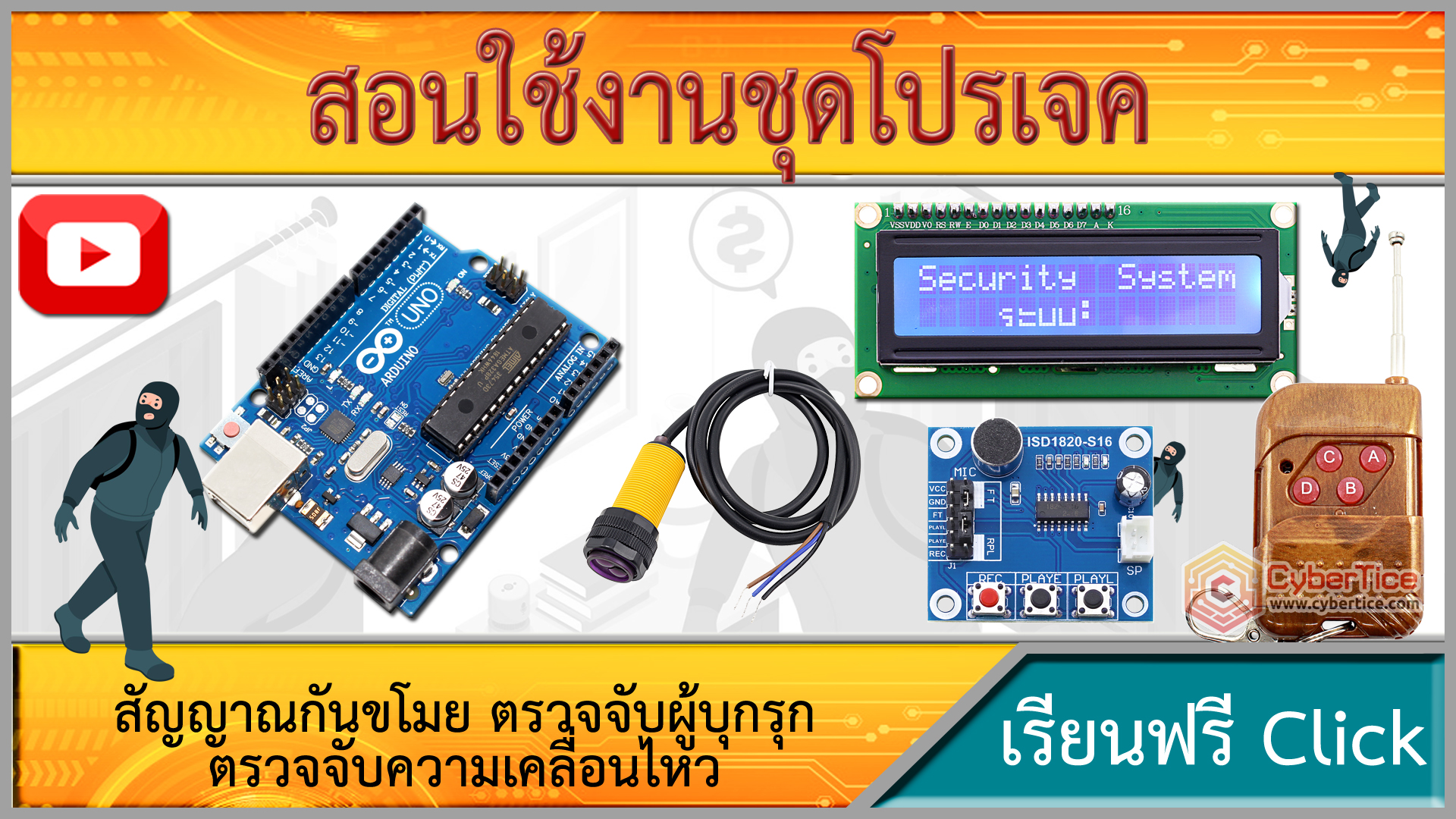
This guide walks through building a complete Arduino alarm system using E18-D80NK infrared sensor, buzzer, two ISD1820 voice modules, a 315MHz RF remote, and a 1602 LCD display. The system can be armed or disarmed remotely and provides both audio and visual feedback.
Components Needed
| Component | Quantity |
|---|---|
| Arduino UNO R3 | 1 |
| E18-D80NK Object Detection Sensor | 1 |
| Active Buzzer | 1 |
| ISD1820 Voice Recording/Playback Module | 2 |
| M4 RF Remote Module 315MHz | 1 set |
| LCD 1602 with I2C Adapter | 1 |
| Jumper wires various colors | - |
Wiring Diagram
E18-D80NK Object Detection Sensor
- Brown wire (5V) → Arduino 5V
- Blue wire (GND) → Arduino GND
- Black wire (Data) → Arduino Pin 2
Active Buzzer
- VCC → 5V
- GND → GND
- I/O → Pin 3
ISD1820 Module #1 (System OFF sound)
- VCC → 5V
- GND → GND
- PLAYE → Pin 4
ISD1820 Module #2 (System ON sound)
- VCC → 5V
- GND → GND
- PLAYE → Pin 5
M4 RF Remote Module 315MHz
- VCC → 5V
- GND → GND
- D0 → Pin 8
- D2 → Pin 9
LCD 1602 (I2C)
- VCC → 5V
- GND → GND
- SDA → A4
- SCL → A5
Pre-Setup Steps

1. Set Remote Address by Soldering
Solder the pins at positions H-8-4 on the M4 RF module to create a unique address code. This prevents signal interference with other remotes in the same area.
2. Record Audio on ISD1820 Modules
- Hold the REC button while speaking (max 10 seconds)
- Record “System OFF” on Module #1
- Record “System ON” on Module #2
- Press PLAY to verify recordings
Note: PLAYE button plays once to completion. PLAYL button plays only while held down.
3. Install LCD I2C Library
Download the LiquidCrystal_I2C library and place it in your Arduino IDE libraries folder (Documents/Arduino/libraries)
Arduino Code for Alarm System
#include <Wire.h>
#include <LiquidCrystal_I2C.h>

// Pin definitions
#define SENSOR_PIN 2
#define BUZZER_PIN 3
#define PLAYE1_PIN 4
#define PLAYE2_PIN 5
#define REMOTE_D0 8
#define REMOTE_D2 9

// System state
bool systemActive = false;

// Initialize LCD (common address 0x27)
LiquidCrystal_I2C lcd(0x27, 16, 2);

void setup() {
  Serial.begin(9600);

  // Configure pins
  pinMode(SENSOR_PIN, INPUT);
  pinMode(BUZZER_PIN, OUTPUT);
  pinMode(PLAYE1_PIN, OUTPUT);
  pinMode(PLAYE2_PIN, OUTPUT);
  pinMode(REMOTE_D0, INPUT);
  pinMode(REMOTE_D2, INPUT);

  // Initialize outputs to LOW
  digitalWrite(PLAYE1_PIN, LOW);
  digitalWrite(PLAYE2_PIN, LOW);
  digitalWrite(BUZZER_PIN, LOW);

  // Initialize LCD
  lcd.init();
  lcd.backlight();
  lcd.setCursor(0, 0);
  lcd.print("System Ready  ");
  lcd.setCursor(0, 1);
  lcd.print("Press B to ON ");

  Serial.println("Alarm System Ready");
}

void loop() {
  int remoteA = digitalRead(REMOTE_D0);  // Button A - Disarm
  int remoteB = digitalRead(REMOTE_D2); // Button B - Arm
  int sensorStatus = digitalRead(SENSOR_PIN);

  // Debounce remote buttons
  static bool lastRemoteA = LOW;
  static bool lastRemoteB = LOW;

  if (remoteA == HIGH && lastRemoteA == LOW) {
    // Disarm system
    systemActive = false;
    digitalWrite(BUZZER_PIN, LOW);
    digitalWrite(PLAYE1_PIN, HIGH);
    delay(500);
    digitalWrite(PLAYE1_PIN, LOW);
    updateDisplay("SYSTEM OFF", "Press B to ON ");
    Serial.println("System OFF - Alarm deactivated");
  }

  if (remoteB == HIGH && lastRemoteB == LOW) {
    // Arm system
    systemActive = true;
    digitalWrite(PLAYE2_PIN, HIGH);
    delay(500);
    digitalWrite(PLAYE2_PIN, LOW);
    updateDisplay("SYSTEM ON ", "Monitoring...");
    Serial.println("System ON - Alarm activated");
  }

  lastRemoteA = remoteA;
  lastRemoteB = remoteB;

  // Detect motion when armed
  if (systemActive) {
    if (sensorStatus == 1) {
      digitalWrite(BUZZER_PIN, HIGH);
      lcd.setCursor(0, 1);
      lcd.print("ALERT!Motion!");
      Serial.print("Sensor: ");
      Serial.println(sensorStatus);
    } else {
      digitalWrite(BUZZER_PIN, LOW);
      lcd.setCursor(0, 1);
      lcd.print("Monitoring... ");
    }
  }

  delay(50);
}

void updateDisplay(String line1, String line2) {
  lcd.clear();
  lcd.setCursor(0, 0);
  lcd.print(line1);
  lcd.setCursor(0, 1);
  lcd.print(line2);
}
Adjustment needed: LCD I2C address may be 0x3F instead of 0x27 depending on your module. Verify with an I2C Scanner sketch first.
Upload and Testing Steps
- Open Arduino IDE and paste the code above
- Select Board: Arduino UNO and the correct Port
- Click Upload and wait for “Done uploading”
- Open Serial Monitor and set baud rate to 9600
Test Arming
Press button B on remote → LCD shows “SYSTEM ON” → ISD1820 Module #2 plays “System ON” audio
Test Motion Detection
Walk toward E18-D80NK → Buzzer sounds → Serial Monitor shows value change from 0 to 1
Test Disarming
Press button A on remote → LCD shows “SYSTEM OFF” → ISD1820 Module #1 plays “System OFF” audio → Sensor stops sending signals to board

Adjusting Detection Range
Rotate the adjustment potentiometer on the E18-D80NK to change detection range (3-80 cm). Adjust the potentiometer on the RF module to change wireless reception range.
Summary
This alarm system consists of 4 main parts: object detection sensor → alert unit (buzzer) → status notification (LCD + audio) → control unit (remote). The system provides dual feedback through both LCD screen and Serial Monitor, with adjustable detection parameters to suit different environments.
อยากทำโปรเจคแบบนี้?
รับทำโปรเจค Arduino / IoT จบงานไว ส่งงานครบ พร้อมสอน
If you need Arduino project service or urgent IoT development, see full service details on the service page
จ้างทำโปรเจคเลย