How to Use GY-521 MPU6050 Tilt Sensor with Arduino
How to Use GY-521 MPU6050 Tilt Sensor with Arduino
The GY-521 module with MPU6050 chip is an IMU (Inertial Measurement Unit) that combines both Accelerometer and Gyroscope. It measures acceleration and rotation across 3 axes. Easy to use with I2C Protocol and available libraries. This tutorial covers wiring and code to read tilt values and control LEDs.

Required Components
- Arduino UNO R3
- USB cable for code upload
- 9V 2A Adapter (optional)
- MB-102 Breadboard (830 points)
- Jumper wires (M-M, M-F, F-F)
- 220 Ohm resistors
- Red, Yellow, Green LEDs (1 each)
- GY-521 MPU6050 module
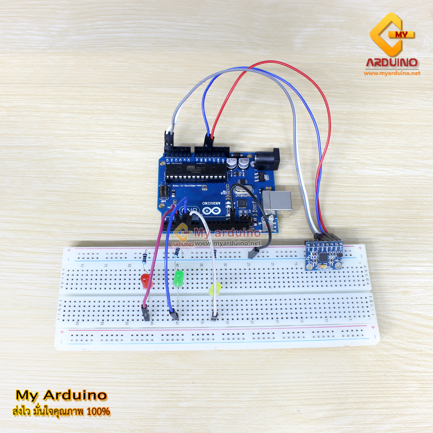
Wiring GY-521 MPU6050 to Arduino
GY-521 uses I2C communication. On Arduino UNO, the I2C pins are A4 (SDA) and A5 (SCL). Other boards like Mega use different pins - check your board pinout before wiring.
| Arduino UNO | GY-521 MPU6050 |
|---|---|
| 5V | VCC |
| GND | GND |
| A4 (SDA) | SDA |
| A5 (SCL) | SCL |
LED Connection
| Arduino Pin | LED Color | Purpose |
|---|---|---|
| Pin 3 | Red | Level position indicator (Z-axis > 150) |
| Pin 4 | Yellow | Perpendicular indicator (X-axis < 50) |
| Pin 5 | Green | Left-right tilt indicator (Y-axis < 50 or > 150) |
Note: Connect 220 Ohm resistor in series with each LED to limit current and prevent damage.

Installing MPU6050 Library
Download the library from GitHub - ElectronicCats/MPU6050 or search for “MPU6050” in Arduino IDE Library Manager.
Installation via Library Manager:
- Open Arduino IDE
- Go to Sketch > Include Library > Manage Libraries
- Search for “MPU6050”
- Select the library and click Install
Arduino Code - Reading Tilt Sensor
#include "Wire.h"
#include "MPU6050.h"

MPU6050 mpu;

// LED pin definitions
const int LED_RED = 3;    // Level indicator (Z-axis)
const int LED_YELLOW = 4;  // Perpendicular indicator (X-axis)
const int LED_GREEN = 5;  // Left-right tilt indicator (Y-axis)

void setup() {
  Serial.begin(9600);

  // Initialize I2C
  Wire.begin();

  // Initialize MPU6050
  mpu.initialize();

  // Verify connection
  if (mpu.testConnection()) {
    Serial.println("MPU6050 initialized successfully");
  } else {
    Serial.println("MPU6050 connection failed");
  }

  // Set LED pins as OUTPUT
  pinMode(LED_RED, OUTPUT);
  pinMode(LED_YELLOW, OUTPUT);
  pinMode(LED_GREEN, OUTPUT);

  // Turn off all LEDs initially
  digitalWrite(LED_RED, LOW);
  digitalWrite(LED_YELLOW, LOW);
  digitalWrite(LED_GREEN, LOW);
}

void loop() {
  int16_t ax, ay, az;
  int16_t gx, gy, gz;

  // Read Accelerometer and Gyroscope values
  mpu.getMotion6(&ax, &ay, &az, &gx, &gy, &gz);

  // Convert Accelerometer values to g (gravity)
  // MPU6050 full-scale is ±2g, which gives approximately ±16384 ADC values
  double accelX = (double)ax / 16384.0;
  double accelY = (double)ay / 16384.0;
  double accelZ = (double)az / 16384.0;

  // Scale values for display (multiply by ~16000)
  int zValue = (int)(az / 109);  // Returns ~150 when level
  int xValue = (int)(ax / 109);
  int yValue = (int)(ay / 109);

  // Display in Serial Monitor
  Serial.print("X: ");
  Serial.print(xValue);
  Serial.print(" | Y: ");
  Serial.print(yValue);
  Serial.print(" | Z: ");
  Serial.println(zValue);

  // Turn off all LEDs first
  digitalWrite(LED_RED, LOW);
  digitalWrite(LED_YELLOW, LOW);
  digitalWrite(LED_GREEN, LOW);

  // Check tilt and light appropriate LED
  // Z > 150 = Level (Z-axis receives full gravity)
  if (zValue > 150) {
    digitalWrite(LED_RED, HIGH);
  }

  // X < 50 = Perpendicular to ground
  if (xValue < 50) {
    digitalWrite(LED_YELLOW, HIGH);
  }

  // Y < 50 or Y > 150 = Tilted to either side
  if (yValue < 50 || yValue > 150) {
    digitalWrite(LED_GREEN, HIGH);
  }

  delay(100);
}
Testing Procedure
- Complete the circuit wiring as shown
- Open Arduino IDE and paste the code above
- Select Board: Arduino UNO from Tools > Board
- Select the correct Port from Tools > Port
- Upload the code to the board
- Open Serial Monitor from Tools > Serial Monitor (baud rate 9600)
- Observe the values and LED behavior when tilting the sensor
Expected Results
| Sensor Position | X Value | Y Value | Z Value | LED On |
|---|---|---|---|---|
| Level (parallel to ground) | ~0 | ~0 | > 150 | Red |
| Perpendicular to ground | < 50 | ~0 | ~0 | Yellow |
| Tilted to right | ~0 | < 50 | ~0 | Green |
| Tilted to left | ~0 | > 150 | ~0 | Green |
Adjustable Points: The threshold values (150, 50) in the code are reference values. Actual readings depend on each module’s calibration. If LEDs don’t light as expected, adjust the threshold values in the code to match your hardware.
Reference Video
อยากทำโปรเจคแบบนี้?
รับทำโปรเจค Arduino / IoT จบงานไว ส่งงานครบ พร้อมสอน
If you need Arduino project service or urgent IoT development, see full service details on the home page
จ้างทำโปรเจคเลย