How to Use ACS712 Current Sensor with Arduino
How to Use ACS712 Current Sensor with Arduino
The ACS712 is a Hall Effect-based current sensor that measures both DC and AC current without breaking the circuit. It outputs a voltage proportional to the current flowing through it, which Arduino can read directly through its Analog pins.
How ACS712 Works
When electric current flows through the copper conductor inside the chip, a magnetic field is generated around the conductor. The Hall Effect sensor inside detects this magnetic field change and converts it into a voltage output that is proportional to the current.
Key characteristics:
- Zero-current output sits at VCC/2 (approximately 2.5V at 5V supply)
- Output shifts up or down based on current direction and magnitude
- Built-in noise filtering circuitry
- Accuracy of ±1.5%
ACS712 Models and Specifications
| Model | Current Range | Sensitivity (mV/A) |
|---|---|---|
| ACS712-05A | -5A to 5A | 185 |
| ACS712-20A | -20A to 20A | 100 |
| ACS712-30A | -30A to 30A | 66 |
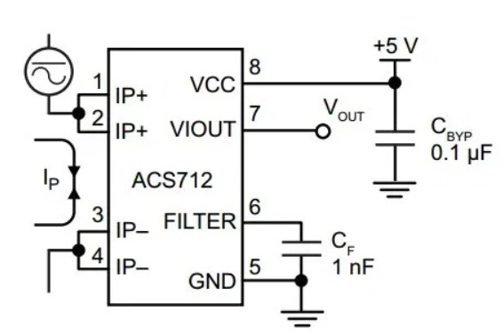
ACS712 Pin Configuration
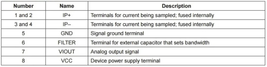
Pin functions:
- Pins 1, 2, 3, 4 — Current measurement terminals (use pins 1-2 or 3-4)
- Pin 5 — Ground (GND)
- Pin 6 — Filter capacitor connection (C)
- Pin 7 — Voltage output (OUT)
- Pin 8 — 5V power supply
Required Components
- Arduino UNO R3
- ACS712 Current Sensor (choose model based on expected current)
- Breadboard
- Jumper wires
- 12V battery or power supply for testing
- Load (motor, lamp, etc.)
Wiring Diagram
Connect as follows:
| Arduino | ACS712 |
|---|---|
| 5V | VCC |
| GND | GND |
| A0 | OUT |
For the load circuit, connect it in series with the ACS712 pins 1-2, then to the power source:
- Power source (+) → ACS712 (+) terminal
- ACS712 (-) terminal → Load → Back to power source (-)
[image: Complete circuit diagram showing Arduino UNO connected to ACS712 with power supply and load in a series configuration]
Current Calculation Formula
Arduino’s ADC reads values from 0-1024 at 0-5V. We need to convert this to current:
// Read ADC value from A0
int adcValue = analogRead(A0);

// Convert ADC to mV (0-1024 → 0-5000mV)
float voltage = (adcValue / 1024.0) * 5000.0;

// voltageOffset is the value at zero current (approximately 2500mV or 2.5V)
float voltageOffset = 2500.0;

// Sensor sensitivity (mV/A) — change based on model
// ACS712-05A: 185
// ACS712-20A: 100
// ACS712-30A: 66
float mVperAmp = 185.0;

// Calculate current
float current = (voltage - voltageOffset) / mVperAmp;
Working Code Example for DC Current Measurement
const int sensorPin = A0;
float voltageOffset = 2500.0; // Adjust this value accordingly
float mVperAmp = 185.0;       // Use 185 for ACS712-05A

void setup() {
  Serial.begin(9600);
}

void loop() {
  // Read ADC value 5 times and average
  float avgValue = 0;
  for (int i = 0; i < 5; i++) {
    avgValue += analogRead(sensorPin);
    delay(1);
  }
  avgValue /= 5.0;

  // Convert to mV
  float voltage = (avgValue / 1024.0) * 5000.0;

  // Calculate current
  float current = (voltage - voltageOffset) / mVperAmp;

  Serial.print("ADC: ");
  Serial.print(avgValue);
  Serial.print(" | Voltage: ");
  Serial.print(voltage, 2);
  Serial.print(" mV | Current: ");
  Serial.print(current, 2);
  Serial.println(" A");

  delay(500);
}
Testing Procedure
- Wire the circuit according to the diagram
- Upload the code to Arduino
- Open Serial Monitor at 9600 baud
- With no load connected, current should read 0.00A
- If reading is not zero, adjust voltageOffset in code until you get 0.00
- Connect the load to the circuit and observe the changing readings
- Use a multimeter to measure actual current and compare with sensor readings
Important Notes
- Choose the right model for your load — a 2A load measured with a 5A sensor gives better resolution than using a 30A sensor
- Calibrate the offset — each sensor has slightly different offset values, adjust to match your actual unit
- Separate power supplies — if your load draws high current, use a separate power supply from Arduino
- Measuring AC requires RMS calculation — this code works for DC; you need additional logic to calculate true RMS for AC
Reference Video
อยากทำโปรเจคแบบนี้?
รับทำโปรเจค Arduino / IoT จบงานไว ส่งงานครบ พร้อมสอน
If you need Arduino project service or urgent IoT development, see full service details on the home page
จ้างทำโปรเจคเลย