Hard
โปรเจกต์ AWS - Arduino Weather Station
Project ที่มีประโยชน์มากซึ่งสร้างขึ้นที่โรงเรียนสำหรับตรวจวัด Weather Data

Project ที่มีประโยชน์มากซึ่งสร้างขึ้นที่โรงเรียนสำหรับตรวจวัด Weather Data

▶ กดเพื่อดูวิดีโอสาธิตโปรเจกต์
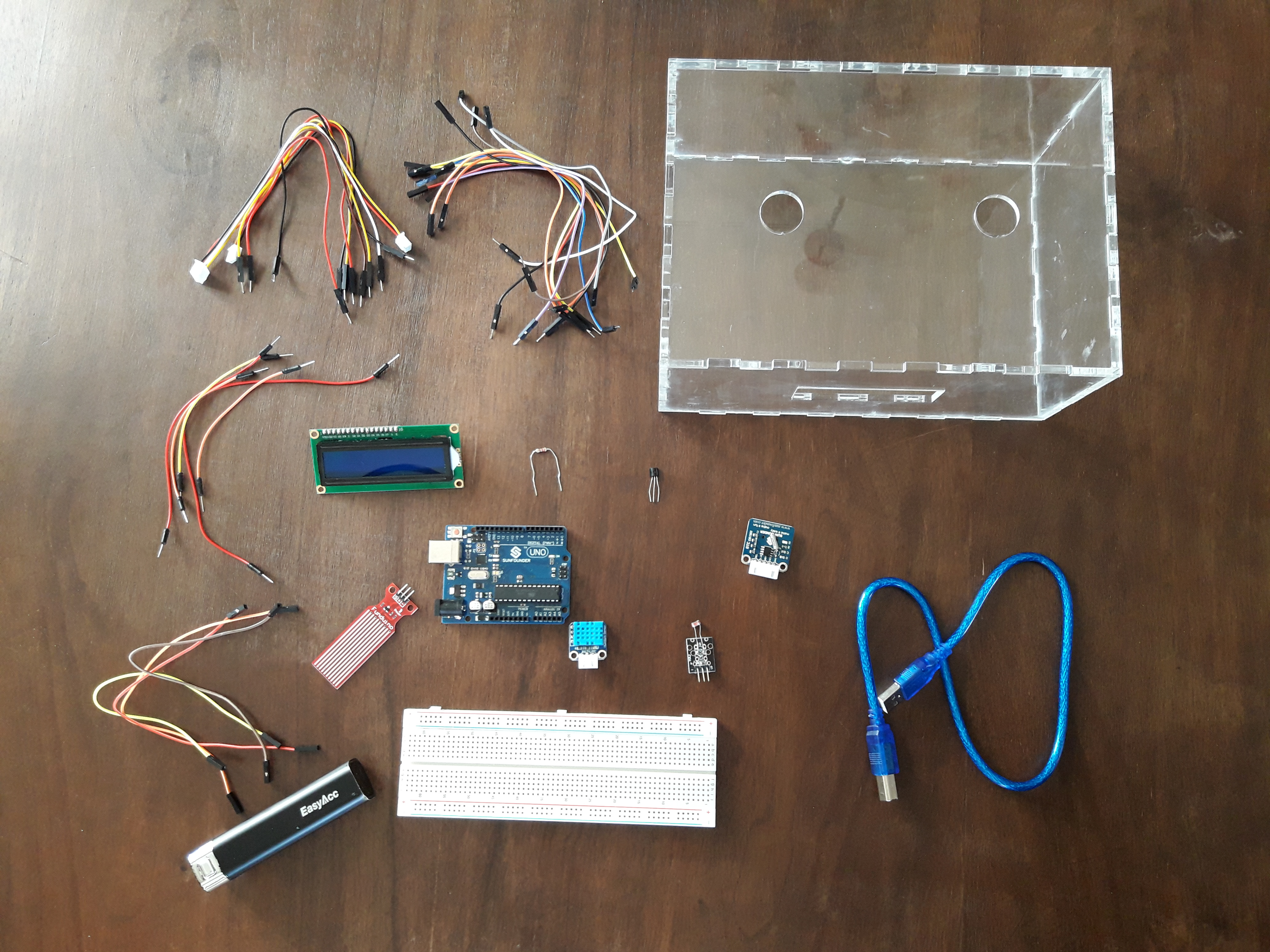
AWS หรือ Arduino Weather Station ให้ข้อมูลสภาพแวดล้อมที่แม่นยำตลอด 24 ชั่วโมง โดยเฉพาะอย่างยิ่ง มันทำงานบนบอร์ด Microcontroller ของ Arduino และรองรับ Sensor แบบครบชุดสำหรับการวิเคราะห์สภาพแวดล้อม
เป้าหมายของส่วนควบคุมนี้คือการตรวจวัดชุดข้อมูลผ่าน Sensor ที่ระบุไว้ข้างต้น และแสดงผลเชื่อมต่อกับผู้ใช้งานผ่านหน้าจอ LCD ขนาดของ "Hardware" โปรเจกต์ที่กะทัดรัดทำให้สามารถบรรจุลงในกล่องขนาดเล็กที่ทำจากเครื่อง Lasercut ได้
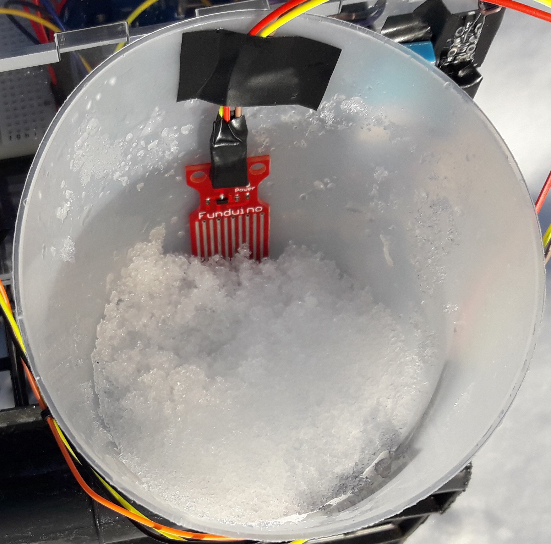


ตัวบ่งชี้ระดับน้ำ (Water-level indicator) ใช้สำหรับบอกระดับน้ำในถังเก็บน้ำด้านบน ซึ่งช่วยให้เราสามารถหลีกเลี่ยงน้ำล้นและทราบระดับน้ำในถังได้ตลอดเวลา
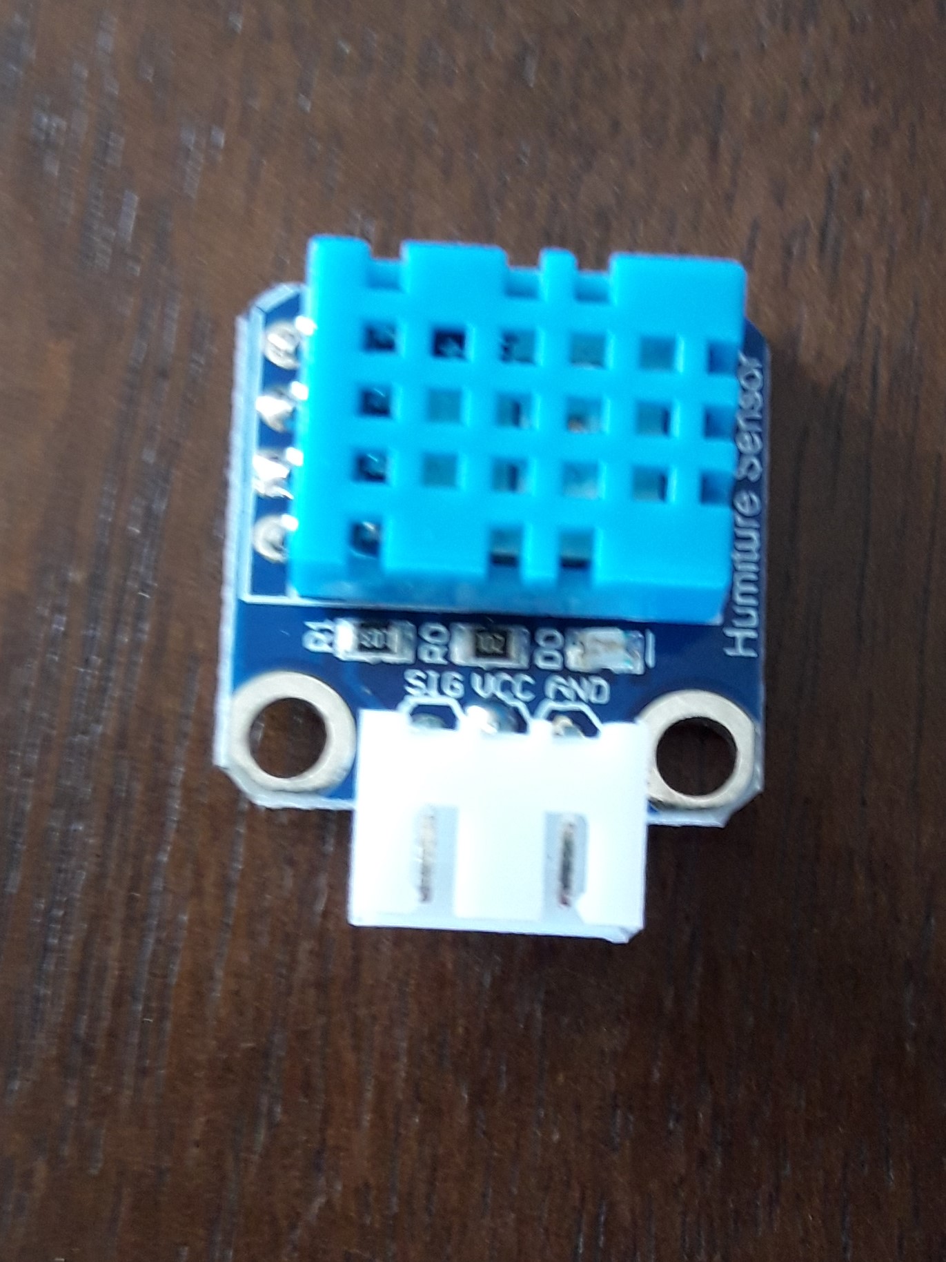
DHT11 เป็น Sensor วัดอุณหภูมิและความชื้นแบบดิจิทัลที่มีการปรับเทียบสัญญาณเอาต์พุตมาแล้ว โดยใช้เทคโนโลยีการเก็บรวบรวมข้อมูล Module เฉพาะทางและเทคโนโลยี Sensor อุณหภูมิและความชื้นแบบดิจิทัล เพื่อให้มั่นใจว่าผลิตภัณฑ์มีความน่าเชื่อถือสูงและมีเสถียรภาพในระยะยาว ผลิตภัณฑ์นี้มีคุณภาพดีเยี่ยม ตอบสนองรวดเร็ว ป้องกันการรบกวนได้ดี ราคาประหยัด และมีข้อดีอื่นๆ อีกมากมาย
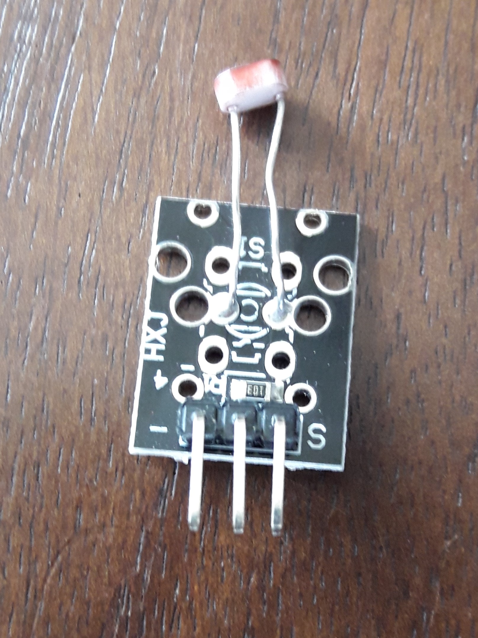
Photoresistors หรือที่รู้จักกันในชื่อ Light Dependent Resistors (LDR) เป็นอุปกรณ์ตรวจจับแสงที่มักใช้เพื่อระบุว่ามีแสงหรือไม่มีแสง หรือเพื่อวัดความเข้มของแสง ในที่มืดค่า Resistance จะสูงมาก แต่เมื่อ Sensor LDR ได้รับแสง ค่า Resistance จะลดลงอย่างรวดเร็วเหลือเพียงไม่กี่ Ohms ขึ้นอยู่กับความเข้มของแสง
LCD1602 พร้อม Bus แบบ I2C เป็น Serial Bus ประเภทหนึ่ง ซึ่งเป็น Serial Bus ประสิทธิภาพสูงที่มีระบบควบคุม Bus และฟังก์ชันการประสานข้อมูลของอุปกรณ์ความเร็วสูงหรือต่ำตามที่ระบบ Multiple-host ต้องการ ตัว Potentiometer สีน้ำเงินบน LCD I2C 1602 ใช้สำหรับปรับ Backlight
I2C ใช้สายสัญญาณแบบ Bidirectional Open-drain เพียงสองเส้น คือ Serial DataLine (SDA) และ Serial Clock Line (SCL) โดยมีการดึงสัญญาณขึ้นด้วย Resistors โดยปกติจะใช้แรงดัน +5 V หรือ +3.3 V แม้ว่าระบบที่ใช้แรงดันไฟฟ้าอื่นจะได้รับอนุญาตเช่นกัน
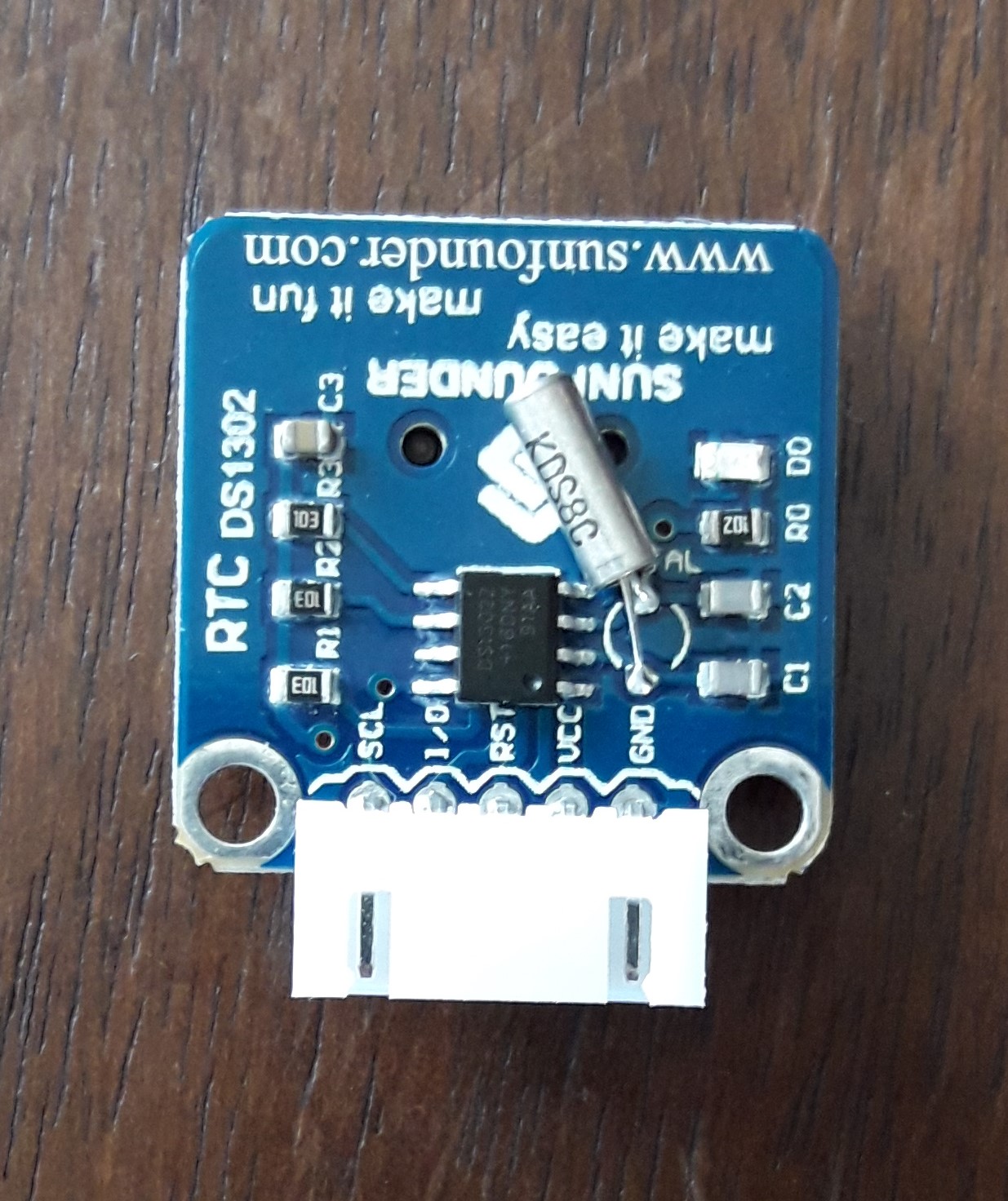
มันทำงานบนพื้นฐานของ Chip DS1302 ภายในซึ่งมีนาฬิกาแบบ Real-time / ปฏิทิน และ Static RAM ขนาด 31 Bytes คุณสามารถดูรูปแบบเวลาเป็น hh/mm/ss ในขณะที่รูปแบบวันที่คือ yyyy/mm/dd
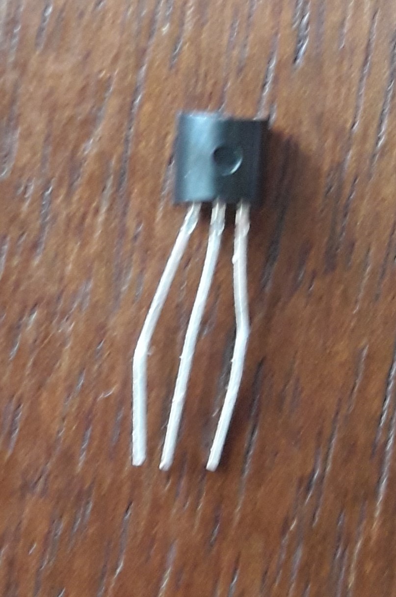
LM35 Precision Temperature sensor เป็น Sensor ที่ตรวจจับอุณหภูมิได้อย่างแม่นยำมาก ตัวแปลงสัญญาณ Analog เป็น Digital (ADC) จะแปลงค่า Analog เป็นค่า Digital โดยประมาณตามสูตร ADCValue = sample * 1024 / reference voltage (+5v) ดังนั้นเมื่อใช้แรงดันอ้างอิง +5 Volt ค่า Digital จะเท่ากับ แรงดัน Input * 205
สองส่วนประกอบนี้ทำงานร่วมกัน: ตัวรับสัญญาณ IR จะทำหน้าที่รับข้อมูลจาก Remote Controller ข้อมูลจะขึ้นอยู่กับว่าคุณกดปุ่มใด ปุ่มต่อไปนี้ถูกเลือกเพื่อกำหนดฟังก์ชันเฉพาะ:


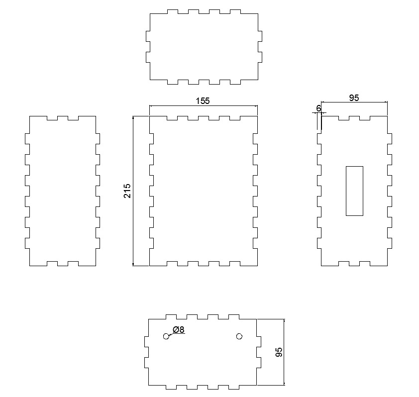
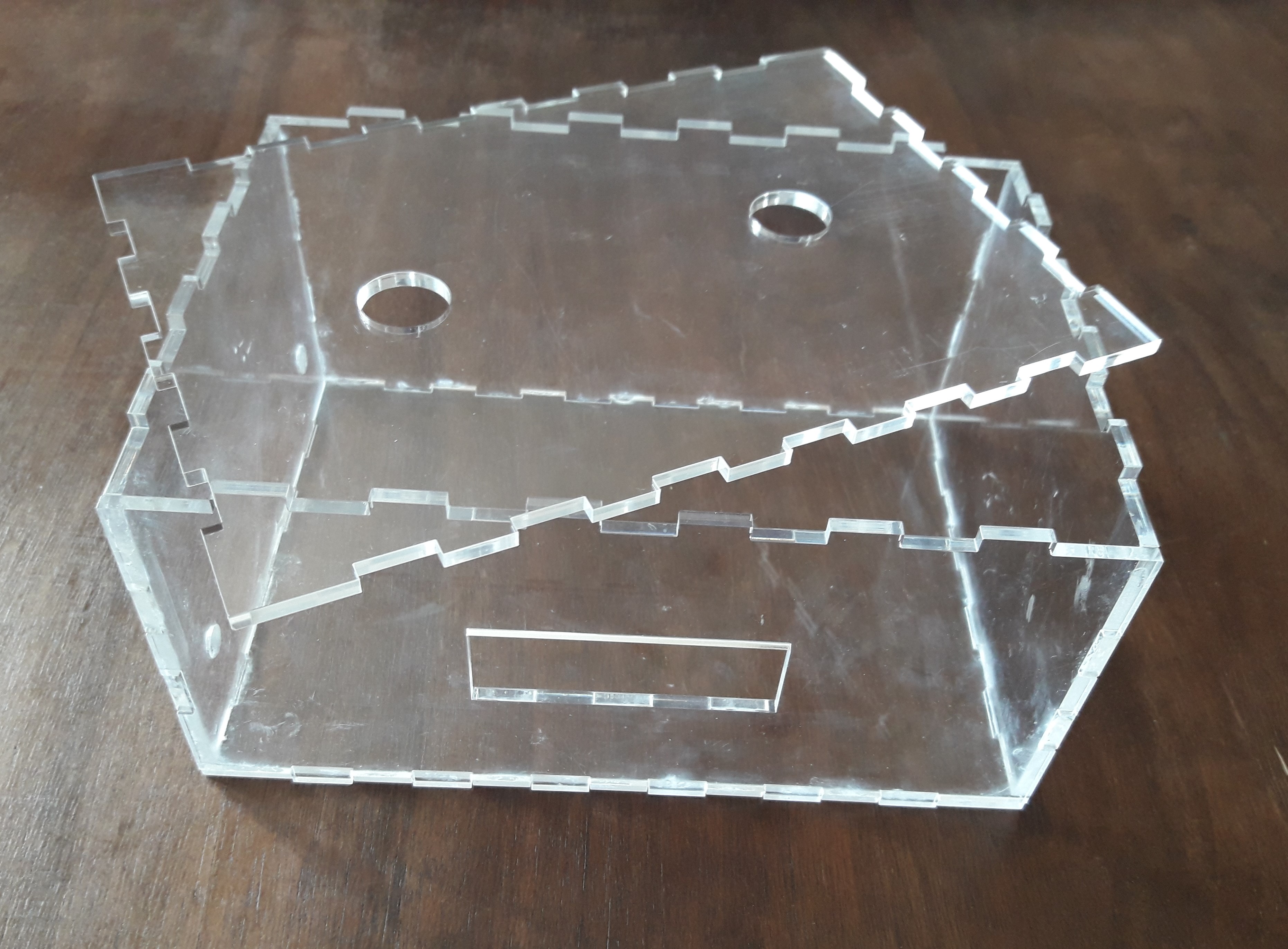
หลังจากพิจารณาขนาดของโปรเจกต์แล้ว เราได้ดำเนินการสร้างกล่อง Plexiglas ขนาดของแต่ละด้านพร้อมกับตำแหน่งการต่อประสานและรูสำหรับสายไฟของ Sensor ออกไปด้านนอกถูกออกแบบด้วย Software Autocad จากนั้นเราได้ตัดชิ้นส่วนด้วยเครื่อง Lasercut และสุดท้ายประกอบเข้าด้วยกันด้วยกาวที่ติดแน่นเป็นพิเศษ
นี่คือรูปภาพ Schematic สำหรับ Arduino Weather Station ซึ่งทำขึ้นด้วย Software Fritzing การเชื่อมต่อค่อนข้างเรียบง่าย

ขั้นตอนที่ 3: การเขียนโปรแกรม Arduino
เราได้เขียน Code บน Arduino IDE โดยใช้ Library ทั้งหมดที่จำเป็น และโปรแกรมให้สถานีตรวจอากาศทำงานตามที่เราต้องการ
ขั้นตอนที่ 4: หลักการทำงาน
AWS (Arduino Weather Station) เป็นสถานีตรวจอากาศที่รับข้อมูลบางอย่างจากสภาพแวดล้อมและทำให้สามารถดูได้โดยใช้ Remote Controller แบบ Infrared เพื่อแสดงผลกับผู้ใช้งาน มันมีหน้าจอ LCD ที่มีหน้าจอแสดงผล 5 แบบที่ผู้ใช้สามารถสลับเปลี่ยนได้
นี่คือหน้าจอต่างๆ:
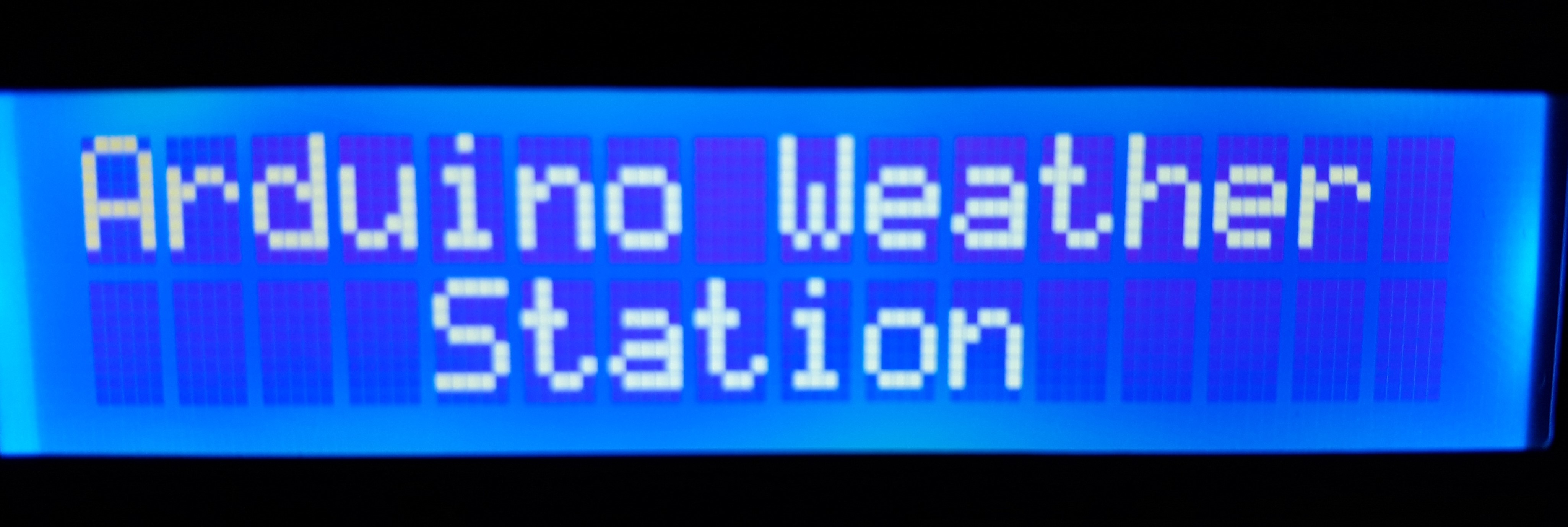
1. หน้าจอหลัก (Home screen): เป็นหน้าจอแรกที่ผู้ใช้เห็นเมื่อเปิด Board ขึ้นมา แสดงชื่อโปรเจกต์ด้วยคำว่า “Arduino Weather Station” ซึ่งมีลูกเล่นการจางหาย (Fading) เฉพาะตัว คุณจะเห็นหน้าจอนี้ทุกครั้งหลังจากที่คุณเรียกดูข้อมูลจาก AWS
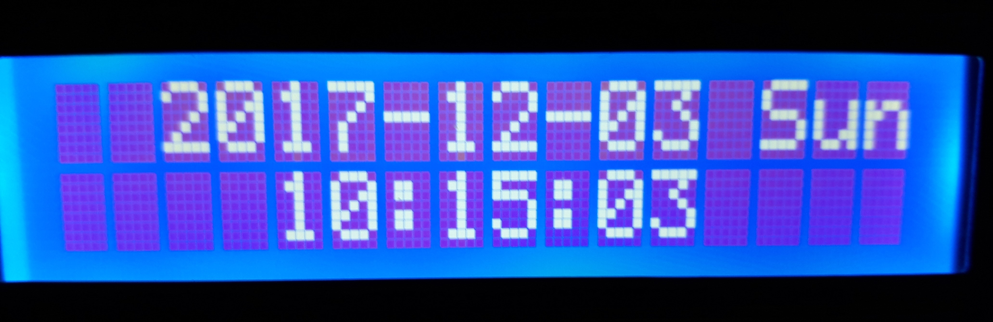
2. หน้าจอวันที่และเวลา (Date and Time screen): เป็นหน้าจอแรกที่ผู้ใช้สามารถเข้าถึงได้เพียงแค่กดปุ่ม 0 บนรีโมทคอนโทรล เมื่อกดแล้ว หน้าจอจะค้างไว้ 10 วินาทีและจะกลับสู่หน้าจอหลัก
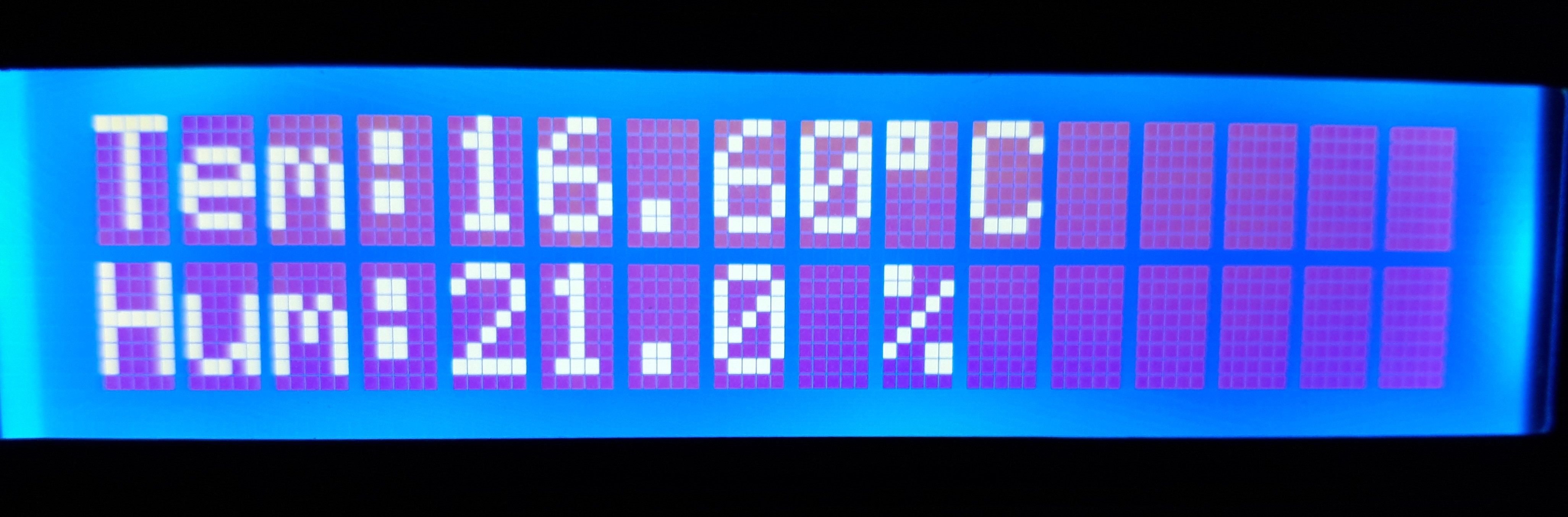
3. หน้าจอความชื้นและอุณหภูมิ (Humidity and Temperature screen): เป็นหน้าจอที่ให้ข้อมูลที่ได้รับจาก Sensor DHT11 และ LM35 เกี่ยวกับความชื้นและอุณหภูมิตามลำดับ เชื่อมต่อกับปุ่ม 1 บน Remote Controller และเมื่อกดหน้าจอจะค้างไว้ 10 วินาทีและจะกลับสู่หน้าจอหลัก
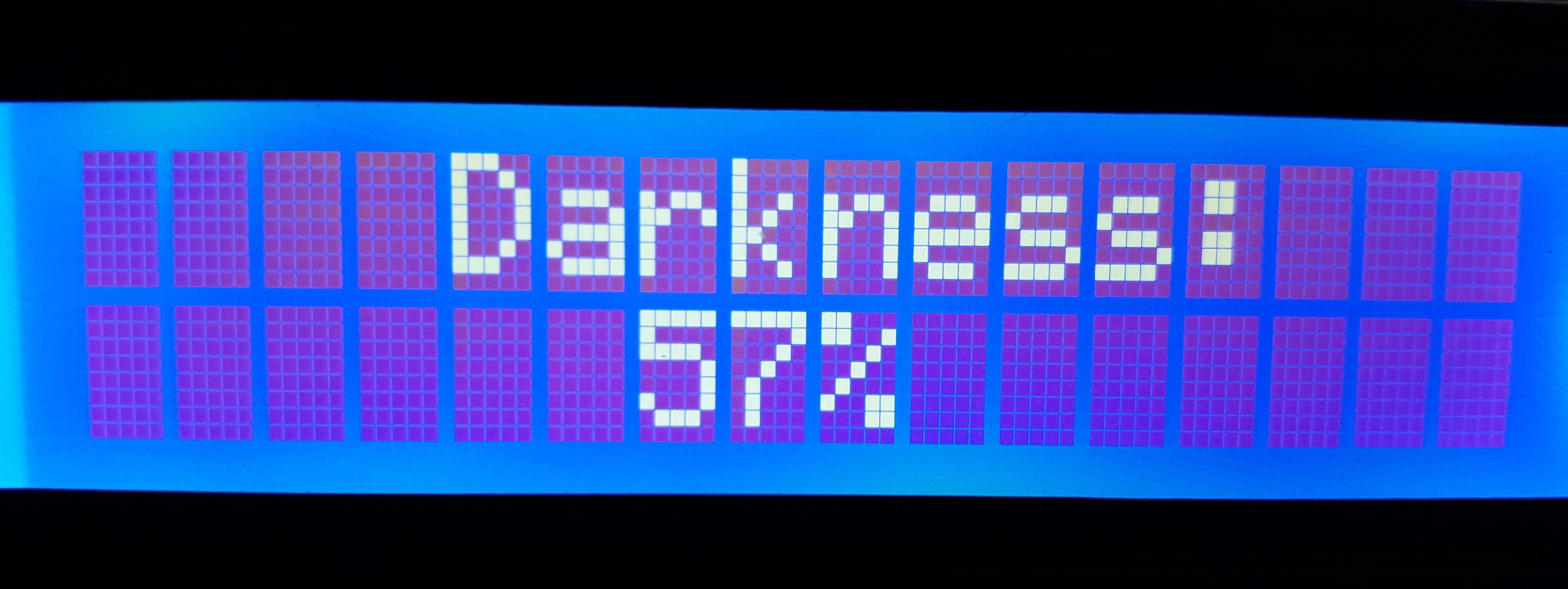
4. หน้าจอความมืด (Darkness screen): เป็นหน้าจอที่ให้ข้อมูลที่ได้รับจาก LDR เกี่ยวกับปริมาณแสงบน Sensor โดยแสดงเป็นเปอร์เซ็นต์ความมืดบน Sensor เชื่อมต่อกับปุ่ม 2 บน Remote Controller และเมื่อกดหน้าจอจะค้างไว้ 10 วินาทีและจะกลับสู่หน้าจอหลัก
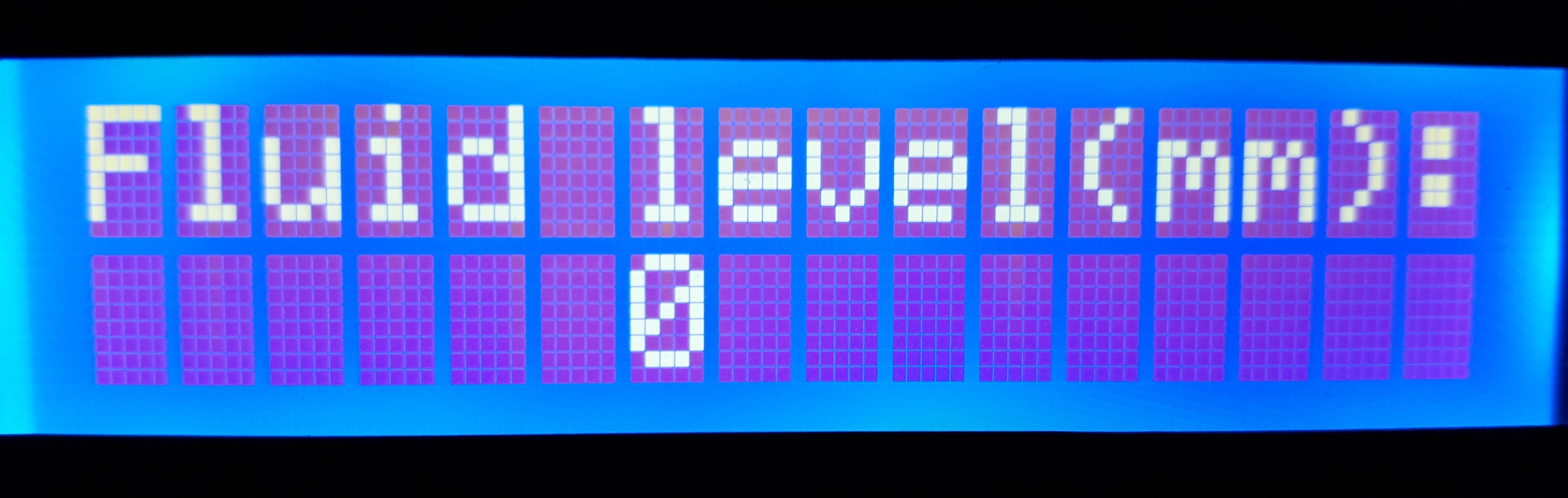
5. หน้าจอระดับของเหลว (Fluid Level screen): หน้าจอนี้ให้ข้อมูลความสูงของปริมาณของเหลวในภาชนะ เชื่อมต่อกับปุ่ม 3 บน Remote Controller และเมื่อกดหน้าจอจะค้างไว้ 10 วินาทีและจะกลับสู่หน้าจอหลัก
สี่หน้าจอสุดท้ายสามารถดูแบบต่อเนื่องกันโดยเว้นระยะห่าง 4 วินาทีได้ โดยการกด ปุ่ม Cycle บนรีโมทคอนโทรล ในโหมดนี้ข้อมูลจะถูกแสดงผลวนรอบเพียงรอบเดียวเท่านั้น
สิ่งแรกที่ต้องพิจารณาเพื่อให้โปรเจกต์นี้มีอายุการใช้งานยาวนานคือการหลีกเลี่ยงไม่ให้ของเหลวหรือสารอันตรายอื่นๆ สัมผัสกับ Board และตัวสถานีโดยรวม
หลังจากการตกตะกอน (เช่น ฝนหรือหิมะ) จำเป็นต้องเทน้ำออกจากภาชนะ ตรวจสอบและทำความสะอาด Sensor
แบตเตอรี่แบบชาร์จไฟได้มีระยะเวลาการใช้งานประมาณสองวัน ดังนั้นจึงจำเป็นต้องชาร์จใหม่ (ประมาณ 2 ชั่วโมง) หากแบตเตอรี่กำลังจะหมด
บางครั้ง Sensor Infrared อาจทำงานไม่ดีเท่าที่ควร ดังนั้นฟังก์ชันของมันอาจถูกขัดจังหวะที่อุณหภูมิต่ำ (ประมาณ 0 องศา) ซึ่งไม่ได้เป็นปัญหาใหญ่อะไร เพียงแค่เปิดกล่องแล้วกดปุ่ม Reset ตัว AWS ก็จะกลับมาทำงานตามปกติอีกครั้ง
หากเรากดปุ่ม Reset ตัว Module RTC DS1302 จะไม่เปลี่ยนค่าวันที่และเวลา เนื่องจากมีแบตเตอรี่สำรองใน Module ที่ใช้งานได้นานประมาณ 10 ปี
หากถอดแหล่งจ่ายไฟของ AWS วันที่และเวลาจะเปลี่ยนไป ในการแก้ปัญหานี้จำเป็นต้องตั้งค่าใหม่ในจุดที่ระบุไว้ใน Code ตามความต้องการของคุณ เมื่ออัปโหลดแล้ว คุณต้องซ่อนการตั้งค่าในโปรแกรมตามที่ระบุด้านล่าง
Before:
Time t(2017, 12, 03, 10, 15, 00, 1);
rtc.time(t);
After:
//Time t(2017, 12, 03, 10, 15, 00, 1)//;
rtc.time(t);
//include sketch libraries
#include
//clock library
#include //clock library
#include //clock library
#include //dht11 library
#include //LCD library
#include //Wire for LCD library
#define lmPin A1 //LM35 attach to A1
LiquidCrystal_I2C lcd(0x27, 16, 2); // set the LCD address to 0x27 for a 16 chars and 2 line display
dht DHT; //create a variable type of dht
const int DHT11_PIN = 4; //attach dht11 to pin 4
const int waterSensor = 0; //set water sensor variable
int waterValue = 0; //variable for water sensor
int mmwaterValue = 0;
int sensorPin = A3; // select the input pin for the potentiometer
int luce = 0; //variable for the ldr
int pluce = 0; //variable for the ldr
float tem = 0; //variable for the temperature
long lmVal = 0; //variable for the LM35
//ir
const int irReceiverPin = 3;
IRrecv irrecv(irReceiverPin); //Creates a variable of type IRrecv
decode_results results;
//define clock variable
uint8_t RST_PIN = 5; //RST pin attach to
uint8_t SDA_PIN = 6; //IO pin attach to
uint8_t SCL_PIN = 7; //clk Pin attach to
/* Create buffers */
char buf[50];
char day[10];
/* Create a DS1302 object */
DS1302 rtc(RST_PIN, SDA_PIN, SCL_PIN);//create a variable type of DS1302
void print_time()
{
/* Get the current time and date from the chip */
Time t = rtc.time();
/* Name the day of the week */
memset(day, 0, sizeof(day));
switch (t.day)
{
case 1:
strcpy(day, "Sun");
break;
case 2:
strcpy(day, "Mon");
break;
case 3:
strcpy(day, "Tue");
break;
case 4:
strcpy(day, "Wed");
break;
case 5:
strcpy(day, "Thu");
break;
case 6:
strcpy(day, "Fri");
break;
case 7:
strcpy(day, "Sat");
break;
}
/* Format the time and date and insert into the temporary buffer */
snprintf(buf, sizeof(buf), "%s %04d-%02d-%02d %02d:%02d:%02d", day, t.yr, t.mon, t.date, t.hr, t.min, t.sec);
/* Print the formatted string to serial so we can see the time */
Serial.println(buf);
lcd.setCursor(2, 0);
lcd.print(t.yr);
lcd.print("-");
lcd.print(t.mon / 10);
lcd.print(t.mon % 10);
lcd.print("-");
lcd.print(t.date / 10);
lcd.print(t.date % 10);
lcd.print(" ");
lcd.print(day);
lcd.setCursor(4, 1);
lcd.print(t.hr);
lcd.print(":");
lcd.print(t.min / 10);
lcd.print(t.min % 10);
lcd.print(":");
lcd.print(t.sec / 10);
lcd.print(t.sec % 10);
}
void setup() {
//clock
Serial.begin(9600);
rtc.write_protect(false);
rtc.halt(false);
//ir
irrecv.enableIRIn(); //enable ir receiver module
lcd.init(); //initialize the lcd
lcd.backlight(); //open the backlight
pinMode(sensorPin, INPUT);
Time t(2017, 12, 03, 10, 15, 00, 1);//initialize the time
/* Set the time and date on the chip */
rtc.time(t);
}
void loop() {
lcd.setCursor(0, 0);
lcd.print("A");
delay(50);
lcd.setCursor(1, 0);
lcd.print("r");
delay(50);
lcd.setCursor(2, 0);
lcd.print("d");
delay(50);
lcd.setCursor(3, 0);
lcd.print("u");
delay(50);
lcd.setCursor(4, 0);
lcd.print("i");
delay(50);
lcd.setCursor(5, 0);
lcd.print("n");
delay(50);
lcd.setCursor(6, 0);
lcd.print("o");
delay(50);
lcd.setCursor(8, 0);
lcd.print("W");
delay(50);
lcd.setCursor(9, 0);
lcd.print("e");
delay(50);
lcd.setCursor(10, 0);
lcd.print("a");
delay(50);
lcd.setCursor(11, 0);
lcd.print("t");
delay(50);
lcd.setCursor(12, 0);
lcd.print("h");
delay(50);
lcd.setCursor(13, 0);
lcd.print("e");
delay(50);
lcd.setCursor(14, 0);
lcd.print("r");
delay(50);
lcd.setCursor(4, 1);
lcd.print("S");
delay(50);
lcd.setCursor(5, 1);
lcd.print("t");
delay(50);
lcd.setCursor(6, 1);
lcd.print("a");
delay(50);
lcd.setCursor(7, 1);
lcd.print("t");
delay(50);
lcd.setCursor(8, 1);
lcd.print("i");
delay(50);
lcd.setCursor(9, 1);
lcd.print("o");
delay(50);
lcd.setCursor(10, 1);
lcd.print("n");
delay(50);
if (irrecv.decode(&results)) //if the ir receiver module receiver data
{
if (results.value == 0xFF6897) //if "0" is pushed print TIME
{
lcd.clear(); //clear the LCD
print_time();
delay(10000); //delay 10000ms
lcd.clear(); //clear the LCD
delay (200); //wait for a while
irrecv.resume(); // Receive the next value
}
if (results.value == 0xFF30CF) //if "1" is pushed print TEMPERATURE and HUMIDITY
{
lcd.clear(); //clear the LCD
//READ DATA of the DHT
int chk = DHT.read11(DHT11_PIN);
// DISPLAY DATA
lcd.setCursor(0, 0);
lcd.print("Tem:");
lmVal = analogRead(lmPin);//read the value of A1
tem = (lmVal * 0.0048828125 * 100);//5/1024=0.0048828125;1000/10=100
lcd.print(tem);//print tem
lcd.print(char(223));//print the unit" ? "
lcd.print("C ");
// Serial.println(" C");
lcd.setCursor(0, 1);
lcd.print("Hum:");
//Serial.print("Hum:");
lcd.print(DHT.humidity, 1); //print the humidity on lcd
//Serial.print(DHT.humidity,1);
lcd.print(" % ");
//Serial.println(" %");
delay(10000); //wait for 3000 ms
lcd.clear(); //clear the LCD
delay(200); //wait for a while
irrecv.resume(); // Receive the next value
}
if (results.value == 0xFF18E7) //if "2" is pushed print the DARKNESS
{
lcd.clear(); //clear the LCD
lcd.setCursor(4, 0); //place the cursor on 4 column, 1 row
lcd.print("Darkness:");
luce = analogRead(sensorPin); //read the ldr
pluce = map(luce, 0, 1023, 0, 100); //the value of the sensor is converted into values from 0 to 100
lcd.setCursor(6, 1); //place the cursor on the middle of the LCD
lcd.print(pluce); //print the percentual
lcd.print("%"); //print the symbol
delay(10000); //delay 10000 ms
lcd.clear(); //clear the LCD
delay(200); //wait for a while
irrecv.resume(); // Receive the next value
}
if (results.value == 0xFF7A85) //if "3" is pushed print the SNOW or WATER LEVEL
{
lcd.clear(); //clear the LCD
lcd.setCursor(0, 0); //place the cursor on 0 column, 1 row
lcd.print("Fluid level(mm):"); //print "Fluid level(mm):"
int waterValue = analogRead(waterSensor); // get water sensor value
lcd.setCursor(6, 1); //place cursor at 6 column,2 row
mmwaterValue = map(waterValue, 0, 1023, 0, 40);
lcd.print(mmwaterValue); //value displayed on lcd
delay(10000); //delay 10000ms
lcd.clear(); //clear the LCD
delay(200);
irrecv.resume(); // Receive the next value
}
if (results.value == 0xFF9867) //if "PRESENTATION" is pushed print TIME, TEM and HUM, DARKNESS and S or W LEVEL one time
{
lcd.clear(); //clear the LCD
print_time();
delay(4000); //delay 10000ms
lcd.clear(); //clear the LCD
delay (200); //wait for a while
//READ DATA of the DHT
int chk = DHT.read11(DHT11_PIN);
// DISPLAY DATA
lcd.setCursor(0, 0);
lcd.print("Tem:");
lmVal = analogRead(lmPin);//read the value of A0
tem = (lmVal * 0.0048828125 * 100);//5/1024=0.0048828125;1000/10=100
lcd.print(tem);//print tem
lcd.print(char(223));//print the unit" ? "
lcd.print("C ");
// Serial.println(" C");
lcd.setCursor(0, 1);
lcd.print("Hum:");
//Serial.print("Hum:");
lcd.print(DHT.humidity, 1); //print the humidity on lcd
//Serial.print(DHT.humidity,1);
lcd.print(" % ");
//Serial.println(" %");
delay(4000); //wait for 3000 ms
lcd.clear(); //clear the LCD
delay(200); //wait for a while
lcd.setCursor(4, 0); //place the cursor on 4 column, 1 row
lcd.print("Darkness:");
luce = analogRead(sensorPin); //read the ldr
pluce = map(luce, 0, 1023, 0, 100); //the value of the sensor is converted into values from 0 to 100
lcd.setCursor(6, 1); //place the cursor on the middle of the LCD
lcd.print(pluce); //print the percentual
lcd.print("%"); //print the symbol
delay(4000); //delay 10000 ms
lcd.clear(); //clear the LCD
delay(200); //wait for a while
lcd.setCursor(0, 0); //place the cursor on 0 column, 1 row
lcd.print("Fluid level(mm):"); //print "Fluid level(mm):"
int waterValue = analogRead(waterSensor); // get water sensor value
lcd.setCursor(6, 1); //place cursor at 6 column,2 row
mmwaterValue = map(waterValue, 0, 1023, 0, 40);
lcd.print(mmwaterValue); //value displayed on lcd
delay(4000); //delay 10000ms
lcd.clear(); //clear the LCD
delay(200);
irrecv.resume(); // Receive the next value
}
}
}
นอกจากการเขียน "Arduino Weather Station" ทีละตัวอักษรแล้ว ยังสามารถเขียนโดยใช้โหมด "switch/case" ได้อีกด้วย
เราได้สร้างสถานีตรวจอากาศด้วย Arduino ซึ่งบันทึกวันที่และเวลาปัจจุบัน และรับข้อมูลสภาพแวดล้อมเพื่อแสดงบนหน้าจอ LCD โดยควบคุมผ่าน Remote Controller แบบ Infrared
สนับสนุนเพื่อรับ Source Code หรือแอปพลิเคชันสำหรับโปรเจกต์นี้