Creating a line follower robot using an Arduino is a popular robotics project. It uses infrared (IR) sensors to detect and follow a line on the ground, typically a black line on a white surface, or vice versa. Below is a step-by-step guide to help you build a simple line follower robot using an Arduino, IR sensors, and a motor driver (like L293D)
Creating a line follower robot using an Arduino is a popular robotics project. It uses infrared (IR) sensors to detect and follow a line on the ground, typically a black line on a white surface, or vice versa. Below is a step-by-step guide to help you build a simple line follower robot using an Arduino, IR sensors, and a motor driver (like L293D)
I've made a full tutorial including 3D printed file as well as the code:
Now let's see how we can make this project.
First of all, you will need a chassis to make this project. I've designed a chassis in Autodesk Fusion 360, and if you have a 3D printer, don't hesitate to download and print it.
Let's assume that you have something to mount the motors.
Now it's time to solder the electrical wire to the motors. The motor will have 2 terminals, you don't need to differentiate which is the positive and which is the negative because it is only used to reverse the motor.
After soldering 4 motors as the picture above. Let's fix the mounting bracket to the motors using 8 M3x40 mm.
Attach the mounting bracket to the motors
You will need to buy the mounting bracket to mount the motors to the 3D printed chassis.
Fix the motors to the chassis
Mounting the chassis with the motor using 8 M3x10 mm.
Mounting the motors to the chassis
The next step is to attach the Arduino board to the chassis using M3 bolts and nuts. You can also use doubled side adhesive tape if you want to :)).
Attach the wheels to the motors. The easiest step in this tutorial, I think :)). Everyone can do it by themself.
Attach the wheels to the chassis
Next step is to connect the L293D motor driver to the Arduino Uno R3.
The L293D is a dual H-Bridge motor driver IC that can control the direction and speed of two DC motors. And it can be connected directly to the Arduino.
Connect L293D motor driver to the Arduino
Wiring setup for 4 motors. Follow the videos for more details.
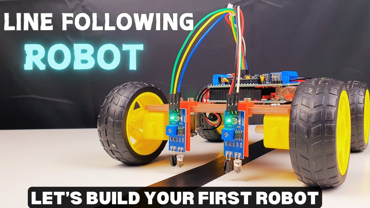
Connect the IR sensors for light detection
You will need two IR sensors (left and right) placed at the front of the robot. These sensors will detect whether the robot is on the line or off the line.
IR sensor modules typically have:
VCC: Power supply (usually 5V)
GND: Ground
OUT: Output (HIGH or LOW depending on whether the sensor detects the line)
The OUT of the sensor on the left will be connected to the A0 and the other one will be connected to the A1.
GND and VCC will be fixed to the 0V and 5V of Arduino respectively.