Designing and Building a Reaction Time Challenge System with Arduino
In the world of Embedded Systems, millisecond-level precision is crucial. This project involves building a reaction speed tester, or a "Fastest Finger First" game, using an Arduino microcontroller board to measure human response capabilities to light signals. This serves as a fundamental basis for learning about Interrupt management, Timing control, and receiving Input values from Digital Sensors.
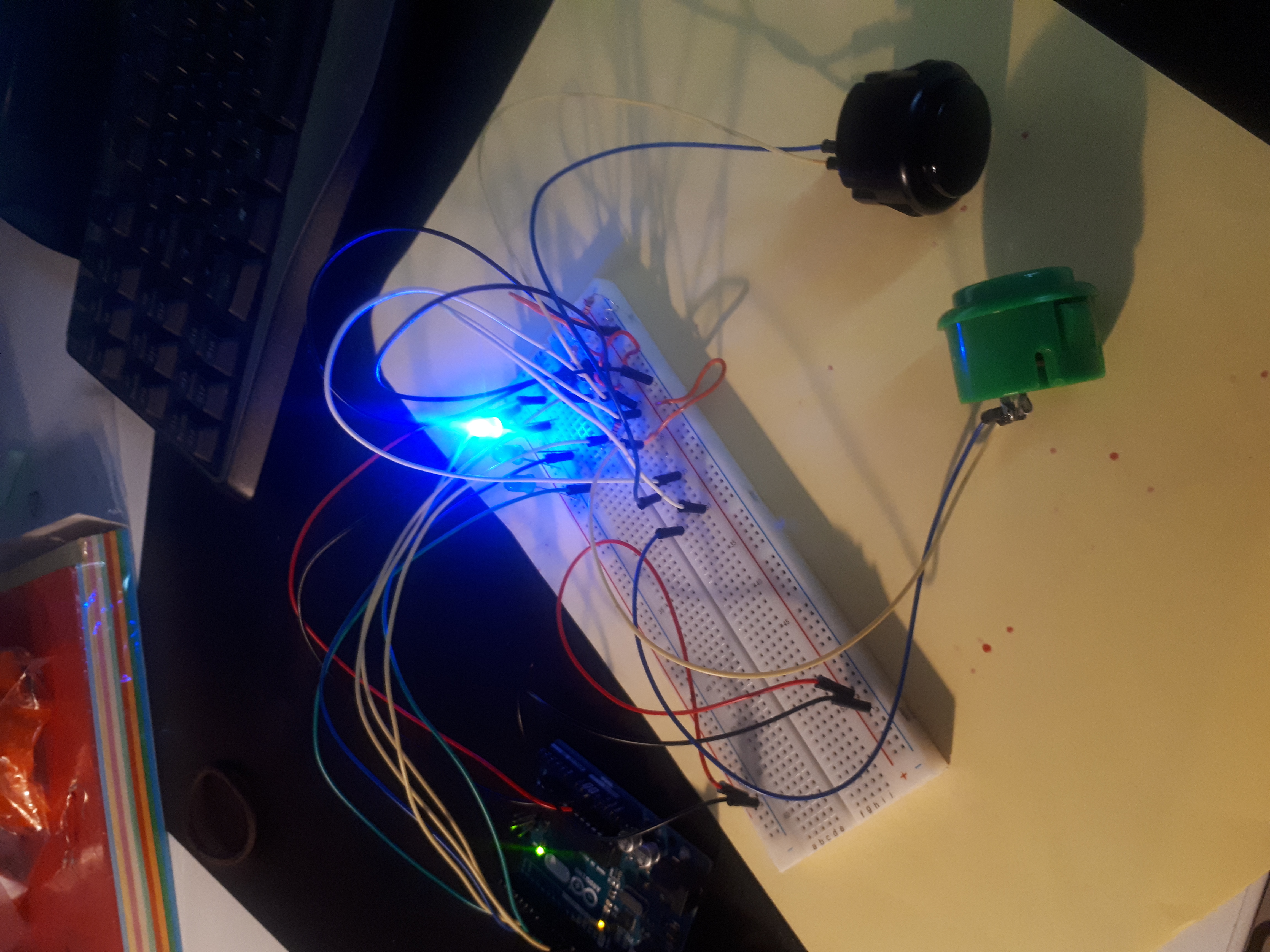
Hardware Components and Operation
The core of this project consists of Push Buttons, which serve as Digital Input, and blue LED lights, which are Outputs for signaling the game status to players. Technically, each Push Button is connected to a digital pin on the Arduino, typically configured with a Pull-up or Pull-down Resistor to prevent a Floating State, which can cause unstable voltage readings and lead to processing errors.
Operational Mechanism and Program Logic (System Logic)
The system is designed to operate in the following Sequential Logic steps:
- System Initialization: When the start game button is pressed, the system turns on the blue LED for 1 second to confirm that the system is ready (System Ready). The light then turns off to enter the preparation phase.
- Randomized Delay: To prevent players from predicting the timing in advance, the program uses the
random()function to create varying delay periods for each round of play. This is a crucial technique for testing true reaction time. - The Game Trigger: When the delay period ends, the blue LED will light up again. At this exact moment, the
millis()time-keeping variable is called to record the Start Timestamp. - Judgment and Processing: The system continuously monitors the Input signals from both players' Push Buttons. Whoever can press their button to change its logic state fastest will have their value locked and the timer stopped immediately to prevent a Race Condition.
Display and Accuracy
In addition to the LED signals, the system also transmits data via Serial Communication protocol for display on a computer screen through the Serial Monitor (accessible from the Tools -> Serial Monitor menu in the Arduino IDE).
The information displayed on the Serial Monitor includes:
- "Get Ready" status to prompt players to prepare.
- Timer values measuring reaction speed in milliseconds.
- A Scoreboard that keeps track of each player's wins.
Using the millis() function instead of delay() for capturing Push Button signals allows the system to be fluid and continuously read Input values (Non-blocking code). This ensures highly accurate measurement of the winner's speed, to a degree that human eyes cannot distinguish. This combination of electrical principles and time-controlled programming makes this project not just a fun game, but a perfect lesson for practicing foundational computer engineering skills.