3 Pins, 30 RGB LEDs, 4 Shift Registers [74HC595]
This article is an extension of the previous one, 3 pins, 32 LEDs, 4 Shift Registers 74HC595. This time, we're upgrading from simple single-color 5mm LEDs to controlling Common Anode RGB LEDs (three-color LEDs with a common positive terminal) to create a wider and more complex range of colors.
Although the basic connection remains similar, using RGB LEDs introduces additional challenges in terms of Breadboard space management, increased jumper wires, and the need for three times the number of resistors, corresponding to the three color pins (red, green, blue).
Furthermore, we will integrate the ShiftPWM Library to help manage PWM (Pulse Width Modulation) signals, allowing us to independently mix colors and adjust the brightness of RGB LEDs via the Shift Register IC, which ordinarily cannot perform hardwired PWM.
List of Equipment and Related Links
- ShiftPWM Library: Github Link (Key to Software PWM implementation)
- SPI Definition: Basic knowledge about SPI
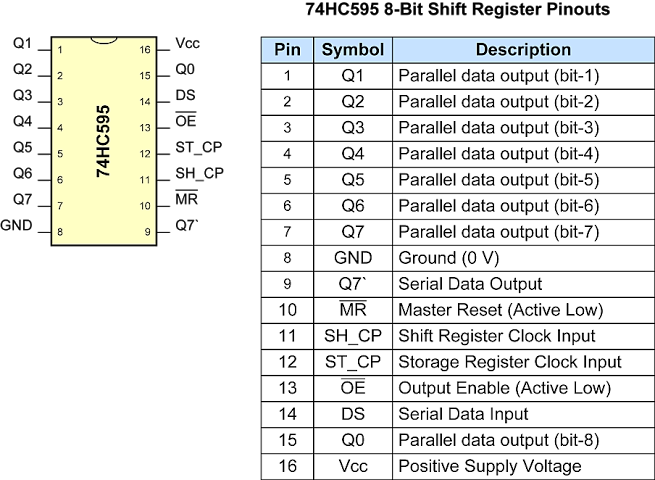
- Datasheet: SN74HC595 Datasheet
- Deep Dive IC: In-depth information about 74HC595
Find more of our work on
Engineering Deep Dive: 74HC595 and Common Anode RGB LED
When controlling multiple RGB LEDs, a major problem is the insufficient number of microcontroller "Pins." This is because one RGB LED requires 3 control pins (R, G, B). If we have 8 LEDs, we would need 24 pins!
74HC595 (Shift Register) is the solution to this problem. It is a Serial-in Parallel-out (SIPO) IC that receives serial data via just a few signal lines and then outputs it as 8 parallel digital signals. Crucially, we can Daisy Chain these ICs to expand the number of output pins indefinitely while using the same number of signal lines from the Arduino.
Understanding Common Anode
The RGB LEDs we use in this project are Common Anode, meaning the longest pin (Anode) must always be connected to the positive power supply (VCC/5V). The R, G, B pins, on the other hand, must receive a "LOW" (0V) signal from the 74HC595 IC to complete the circuit and turn the light on.
- Logic Inversion: In programming, to turn the light ON, we must send a
0value, and to turn it OFF, we must send a1value (or if using the ShiftPWM Library, the library will handle the brightness value conversion for us).
Wiring Phase
The circuit wiring is divided into sets for organization and to prevent signal confusion. This is because each IC can only control 2 RGB LEDs plus 2 additional pins (since one LED uses 3 channels).
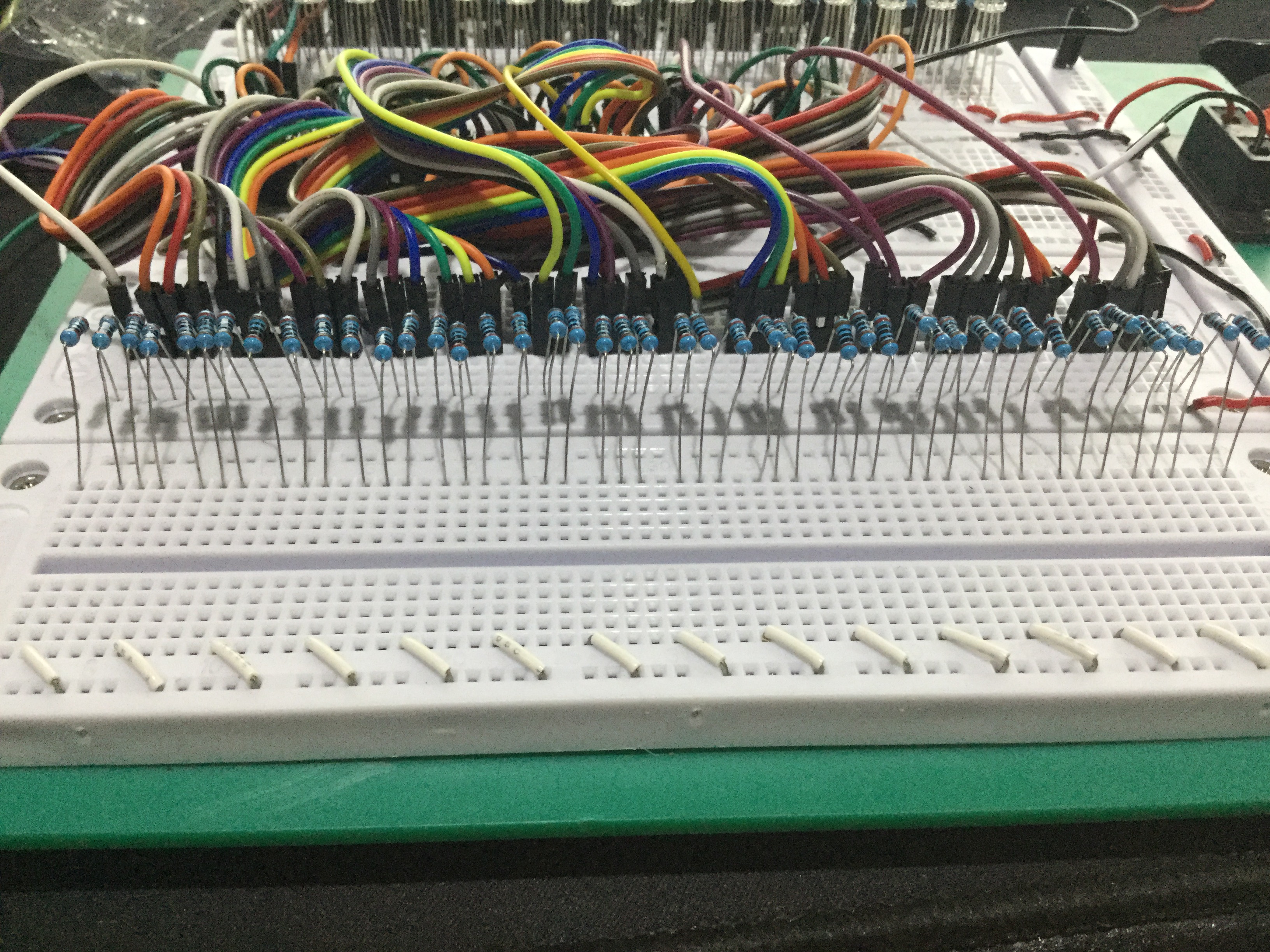
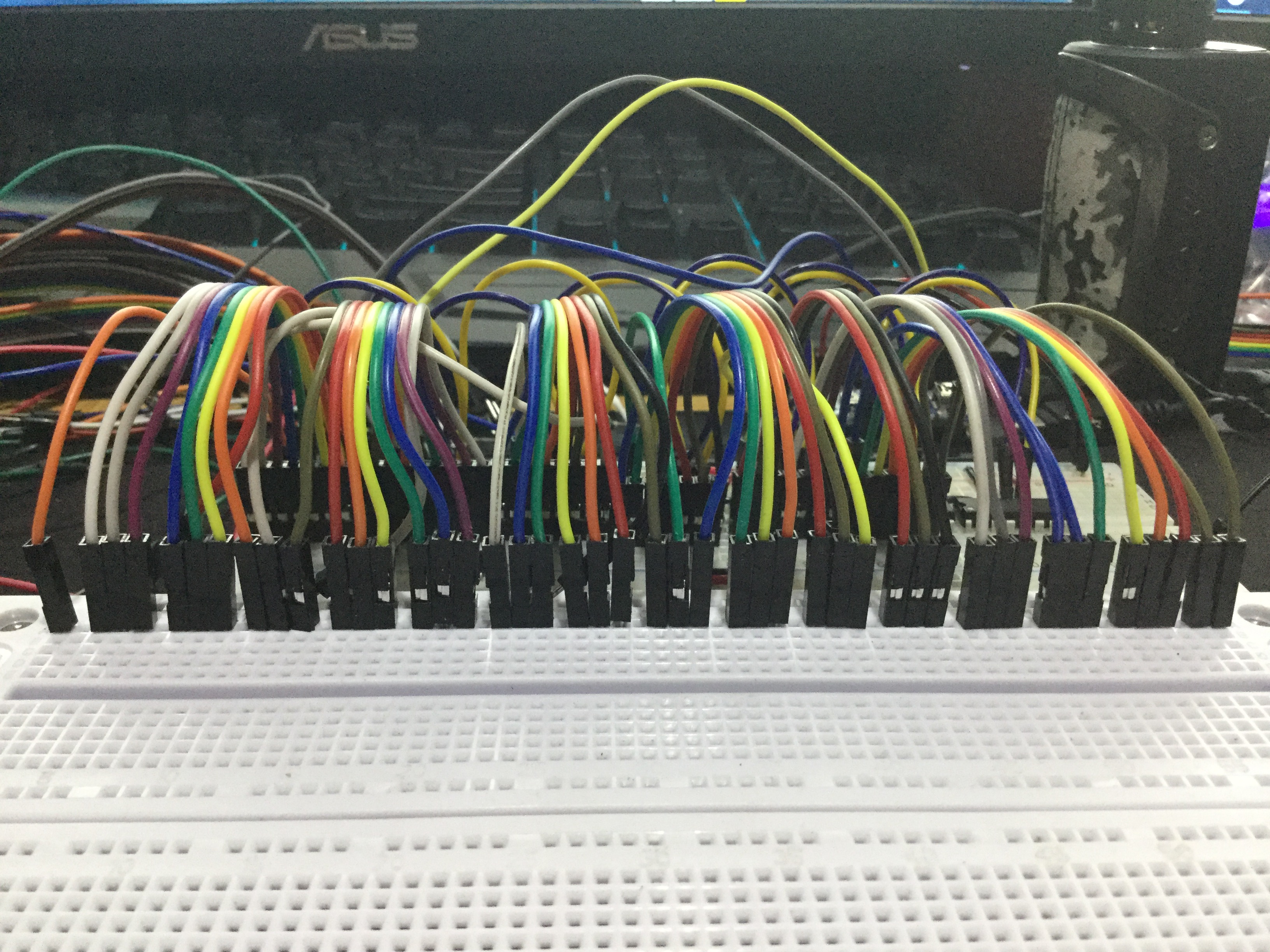 Starting the placement of the first Shift Register IC set and connecting basic signal lines (VCC, GND, Latch, Clock, Data)
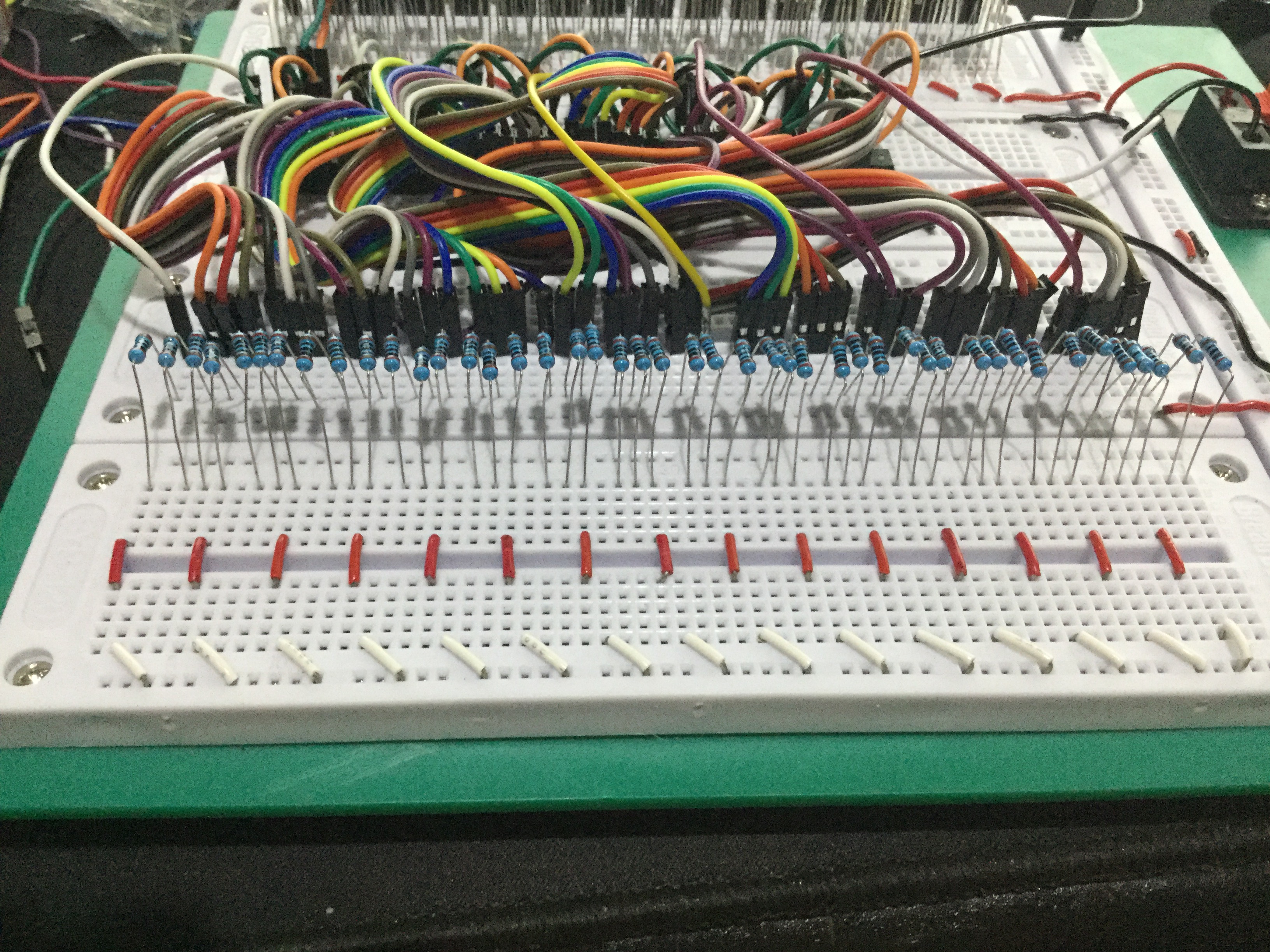
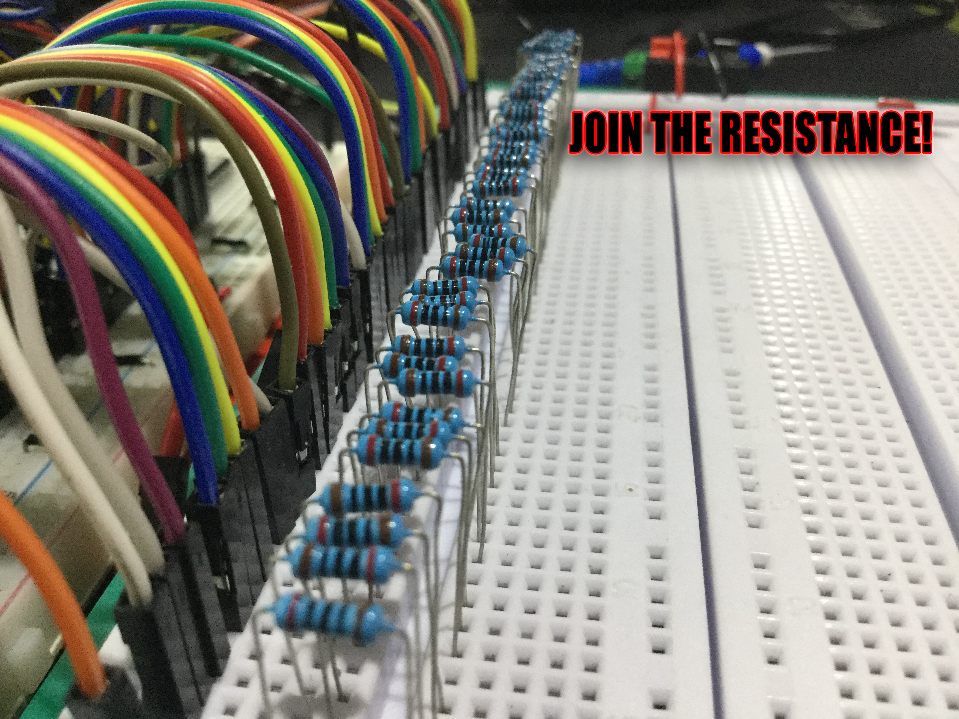 Adding resistors is very important to limit the current flowing through the LEDs and ICs, which could otherwise damage the components. For this project, resistors of 220-330 ohms should be used.
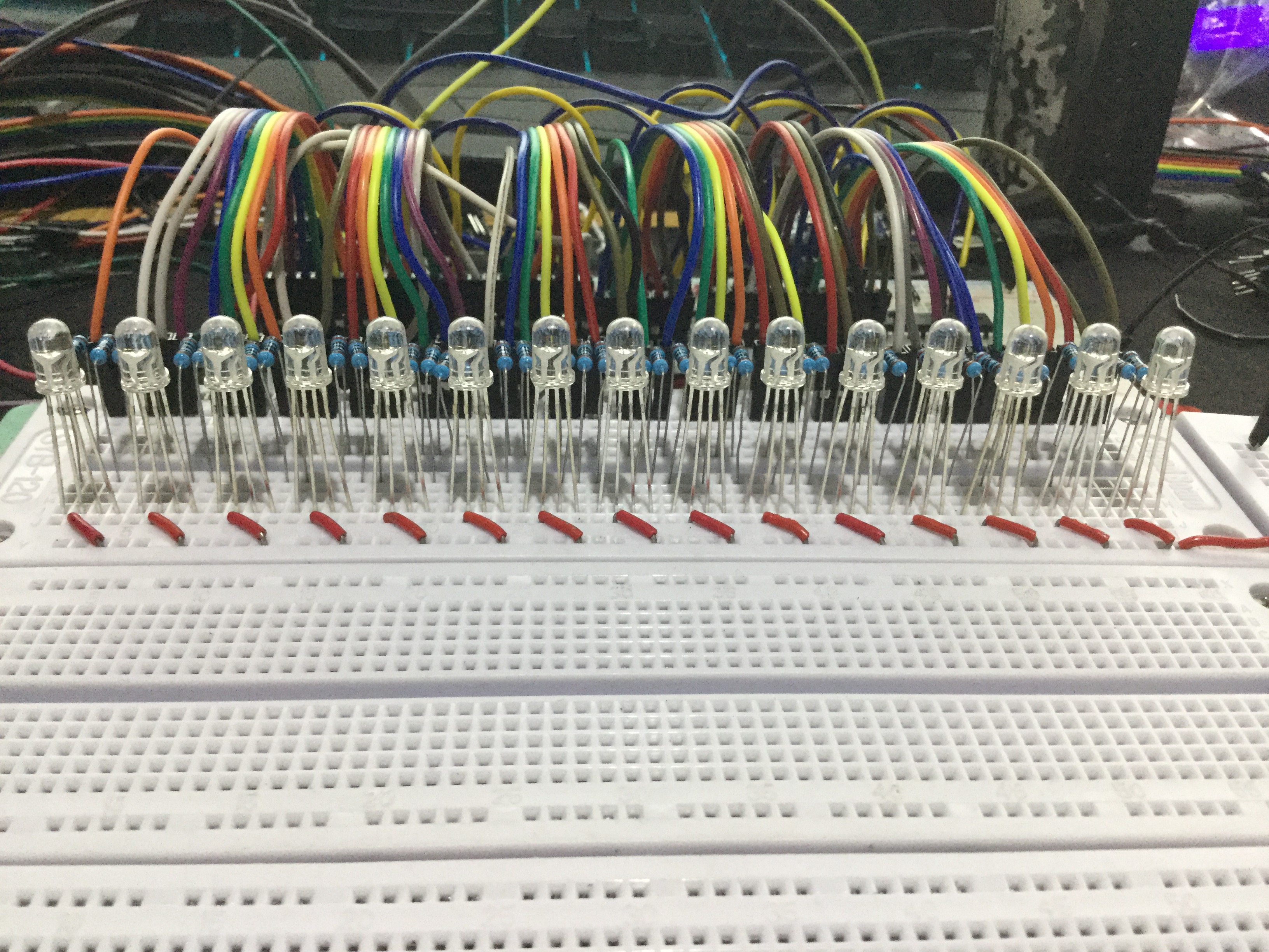 Installing the first set of RGB LEDs into the system.
 Expanding the system with the second Shift Register set by connecting the Q7' (Serial Out) pin of the first to the DS (Serial Data In) pin of the next.
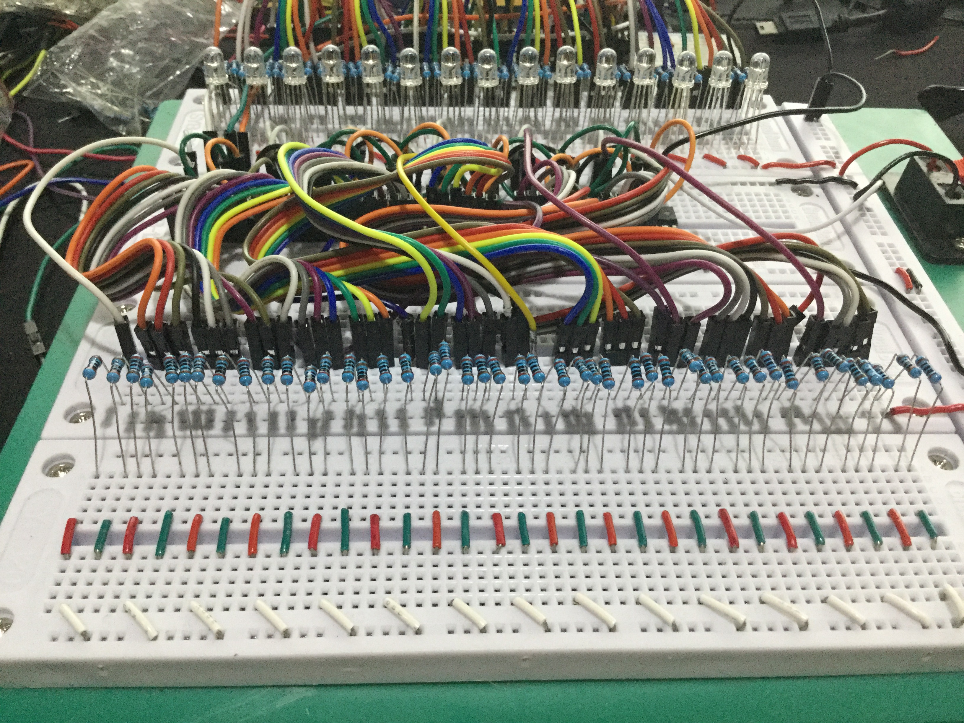
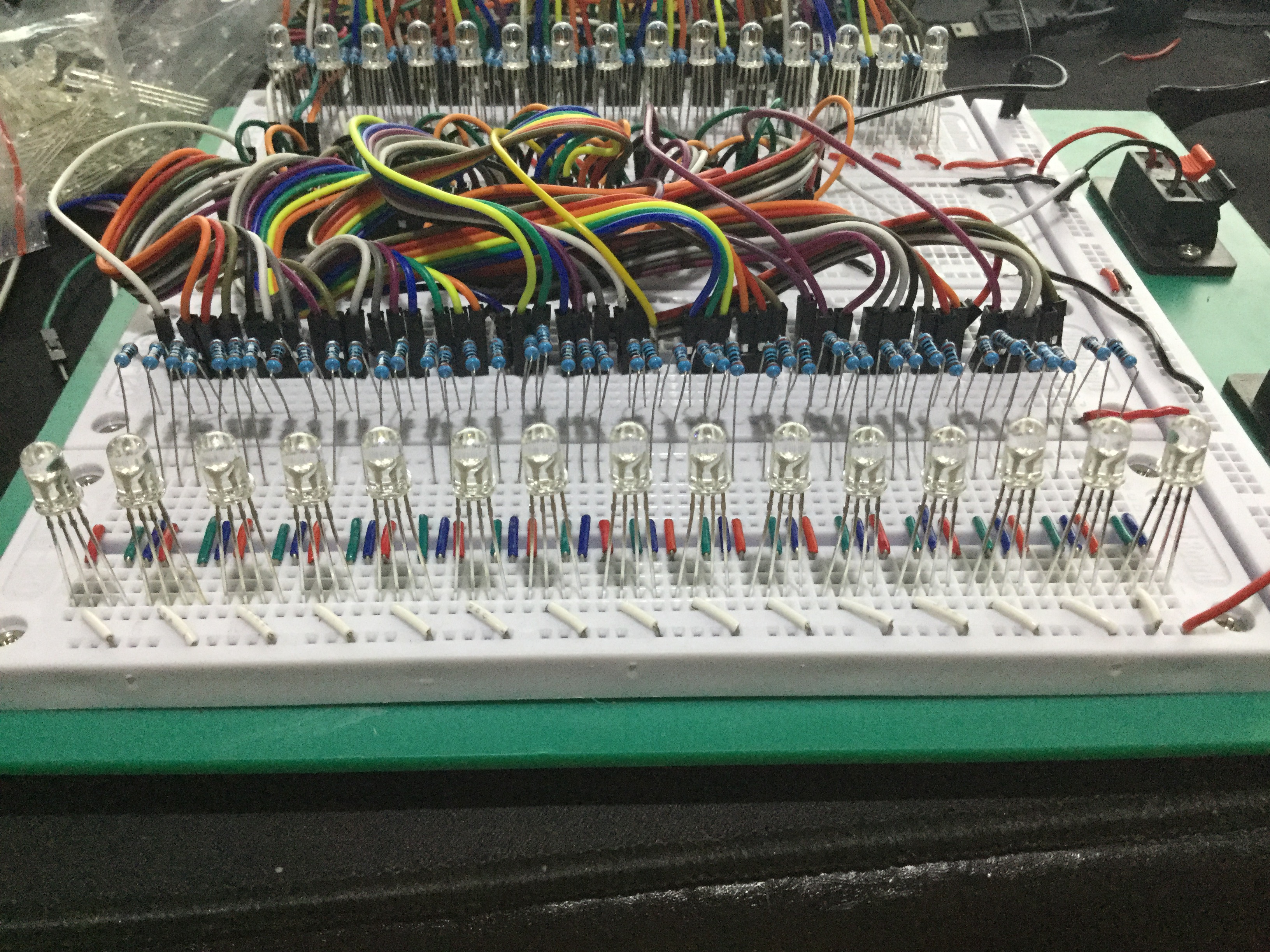 Overview of the increasingly complex jumper wiring as the number of LEDs increases.
Software Operation and ShiftPWM Library
This project is unique in its use of SPI (Serial Peripheral Interface), a high-speed communication protocol available on Arduino (pin 11 for Data and pin 13 for Clock on an Uno board).
Why use ShiftPWM?
Normally, the 74HC595 can only send ON or OFF signals. However, ShiftPWM uses a high-frequency interrupt-driven technique to rapidly switch output pins ON and OFF (Pulse Width Modulation) at a speed imperceptible to the human eye, allowing us to set brightness values from 0-255 for each color of the RGB LED.
Basic Code Logic:
- Initialization: Define the number of Shift Register ICs and the maximum brightness value.
- SPI Communication: The library handles data transmission via SPI to the ICs as a background process.
- Color Mapping: When we call
ShiftPWM.setRGB(led_number, r, g, b), the library calculates which bit of which IC the color value needs to be sent to and transmits the data accurately.
Demonstration Video
Watch the results of color mixing and various effects using the Shift Register and RGB LEDs in the video below:
If you want to create a project with spectacular lighting effects but are limited by the number of Arduino pins, using a Shift Register in conjunction with ShiftPWM is the most efficient and worthwhile solution!
 Follow for more engineering knowledge on YouTube @HeathenHacks