Please visit https://proteshea.com/control-pan-tilt-module-with-4-way-joystick-and-arduino-uno/ for a complete list of materials needed for this project.
Introduction
If you haven’t read our Getting Started Guide for the Arduino Uno Rev3 (Uno), please read that first. Otherwise, continue reading. In this project, we’ll be interfacing a 4-way joystick to control the pan and tilt of a small camera module. This Pan-Tilt system consists of two Servo Motors, which are essential for robotics and CCTV systems. The joystick consists of four Limit Switches. Each limit switch has two leads, so we’ll need a total of eight Digital I/O pins; four will be used as outputs and four will be used as inputs. The servo motors are controlled via Pulse Width Modulation (PWM), so we’ll need two PWM channels on the Uno to set precise angular positions.
4-Way Joystick Mechanism
The 4-way joystick consists of four limit switches which are pressed when the joystick is moved left, right, up, or down. This model differs from an Analog joystick (the type with a Potentiometer stick). The switches are normally-open (NO) which means that when the switch is not pressed, the two leads are disconnected internally. When the switch is pressed, the two leads become connected internally.
To do a quick test, use the continuity function on a multimeter. Place one probe on one lead and the other probe on the second lead of the limit switch. You should not have continuity. Now, move the joystick to press the limit switch that you are probing. You should have continuity.
An animation is shown below that illustrates which limit switch is pressed when the joystick is moved in a particular direction. For example, when the joystick is moved up, limit switch 3 is pressed.
The Importance of Pull-Down Resistors
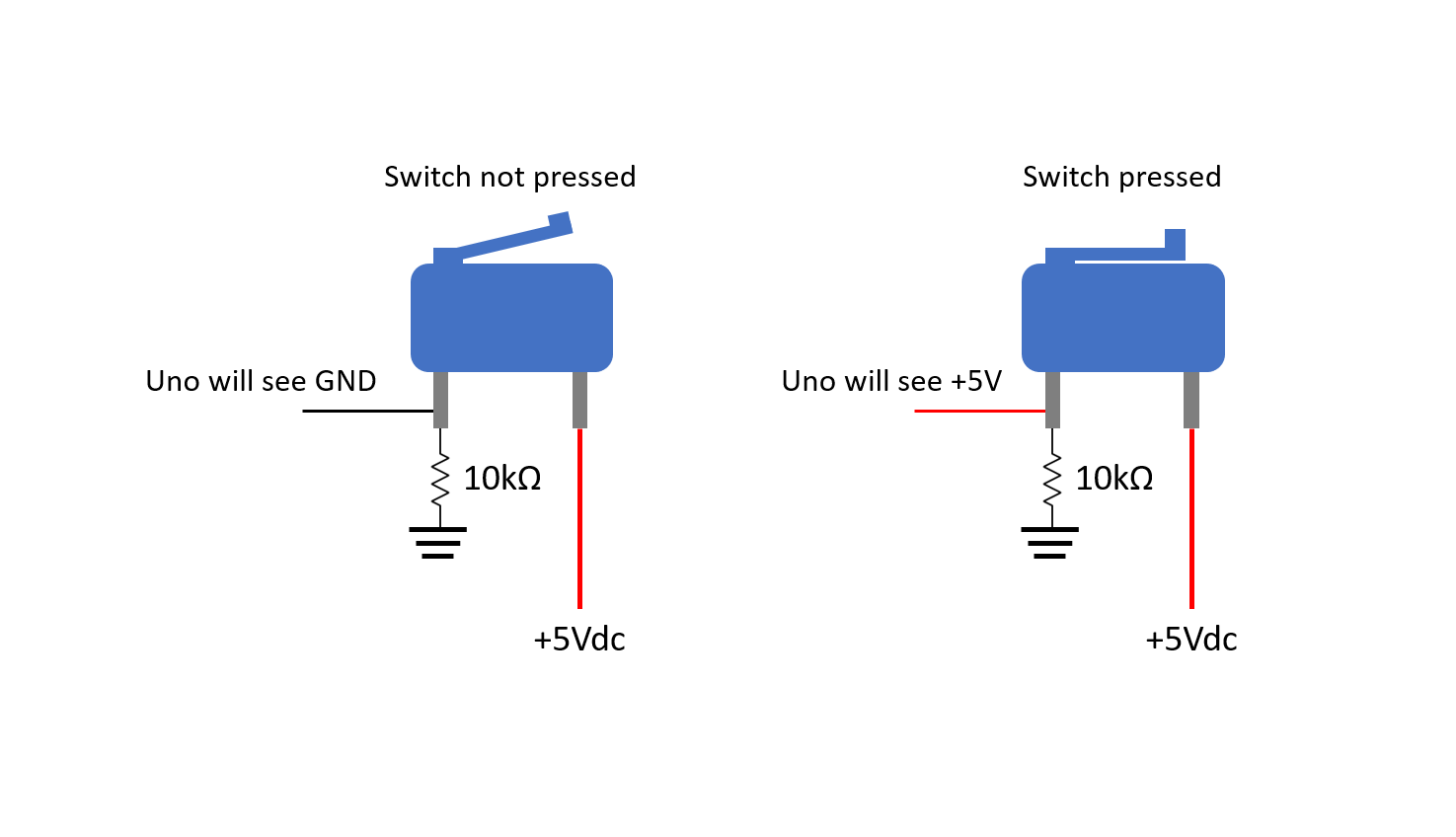
Pull-down resistors must be used on the output side of each limit switch to prevent a floating input pin that is connected to the Uno. A floating pin means that the signal level can randomly switch between +5V (if this is your high signal voltage) and GND. This condition, known as Floating Input, makes the pin susceptible to electrical noise, causing the Uno to randomly read values fluctuating between HIGH (+5V) and LOW (GND). This can cause the Uno to think that the switch is activated, and it will perform the function accordingly. For example, let’s say we have a piece of code that checks if a digital input is high and if it is, an LED will turn on. If the digital input is low (what we want as our default state), the LED will remain OFF. If the input is floating, the pin could randomly go high and cause the LED to turn ON even though the switch is off.
The Pull-down Resistor ensures that the voltage at the Input pin is always pulled down to Ground (0V) when the switch is open. When the switch is pressed, voltage from the +5V supply flows through the switch into the Input pin, allowing the Uno to accurately read a HIGH value.
The schematic below shows a pull-down resistor connected to the output of a switch (input to Uno). When the switch is not pressed (OFF), the output will be pulled to GND. When the switch is pressed (ON), the output will be pulled to +5V.
Control with Pulse Width Modulation (PWM)
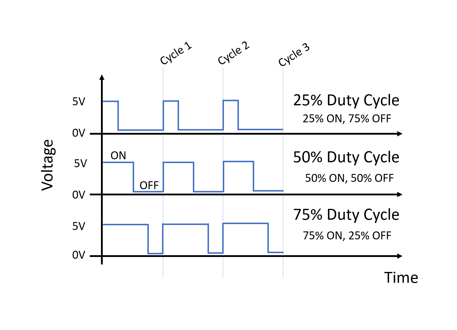
PWM is used in a wide variety of applications such as robotics and control. It is a technique to simulate a continuous Analog output voltage using a Digital signal. A digital output can be high (usually +5 or +3V3) or low (GND). To vary the voltage, we have to change something called the duty cycle. Duty cycle is the ratio of ON vs OFF time in one cycle. For example, a 50% duty cycle would mean that the signal is ON for 50% and OFF for 50% of one cycle. If we have a 75% duty cycle, the signal is ON for 75% and OFF for 25% of one cycle.
For servo motors, the PWM signal determines the "position" of the motor's shaft. Typically, servos require a frequency of 50Hz (a period of 20ms) and a pulse width between 1ms and 2ms to set angles from 0 to 180 degrees.
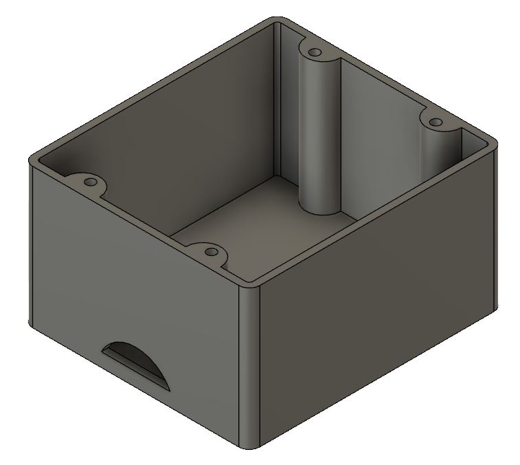
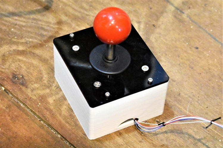
Mechanical Enclosure Design
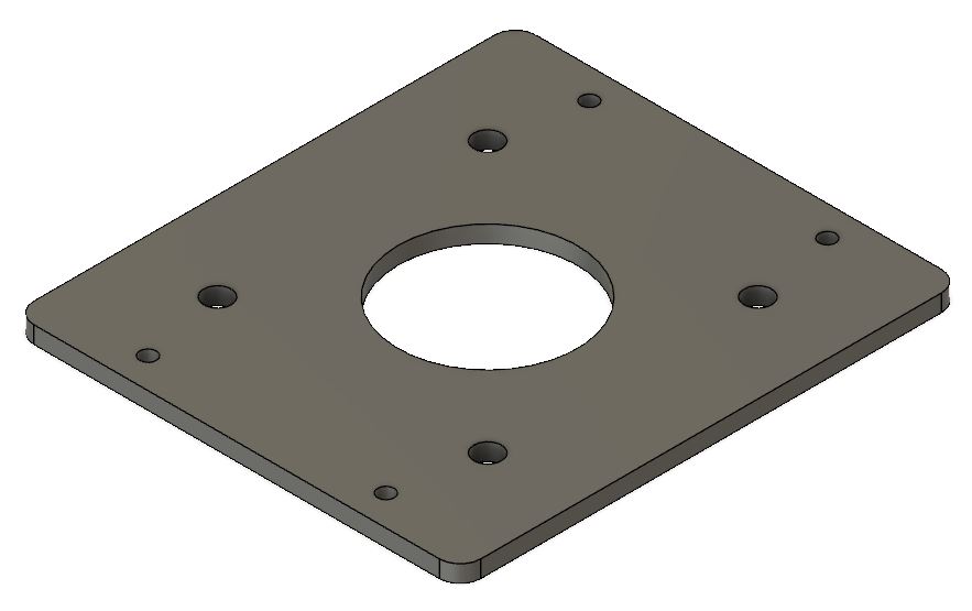
The joystick does not come with a mechanical enclosure to mount it into, so we have to design our own. We used a 3D printer to make ours, or you could also make it out of acrylic. We also redesigned the aluminum top plate to give more clearance for the limit switches. This was manufactured with a piece of 1/8″ thick acrylic and a laser cutter.
Wiring the Joystick
The limit switches on the joystick do not come prewired. You can either use female quick disconnects or solder wire straight to the leads. We opted to solder wire straight to the leads for robustness and reduced contact resistance. We used 30 AWG wire since there is not much current flowing through the wire (only for checking Logic status), but you can use anywhere between 24 – 30 AWG wire. If you can, try to label or color code each wire so that it is easier to identify which wire goes to which limit switch on the joystick. Otherwise, you will be probing each wire with a voltmeter to determine which wire is what.
Wiring Steps:
- Cut each wire to 2′ in length. You can shorten or lengthen them depending on how long you want your wire harness to be.
- Strip about a 1/2″ of insulation off of each wire.
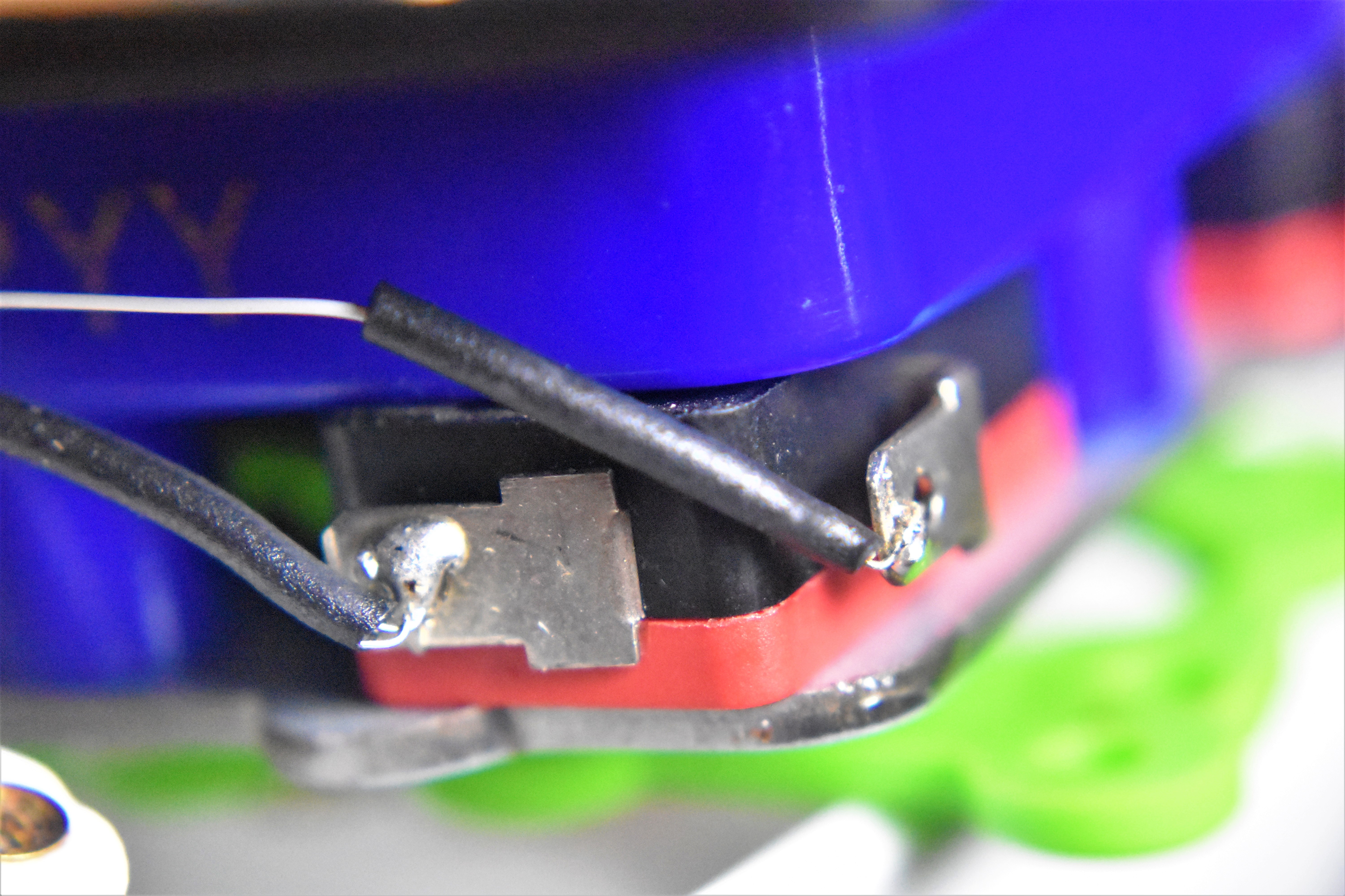
- Solder a wire to each lead of the limit switches.
- To prevent short circuits from one lead to an adjacent lead, add a piece of heat shrink as shown in the image below.
- Once each wire is soldered on, pass them through the hole in the enclosure and mount the joystick to the enclosure.
On the end of each wire, crimp on a male crimp pin so it is easier to stick into a hole on the breadboard. The 30 AWG wire is too fragile without the crimp pin. One benefit of using thicker gauge wire is that you most likely wouldn’t need the male crimp pins. We also added a piece of heat shrink to the ends of each wire. Insert the crimp pins into the breadboard, or straight into the female header on the Uno if your wire harness is long enough.
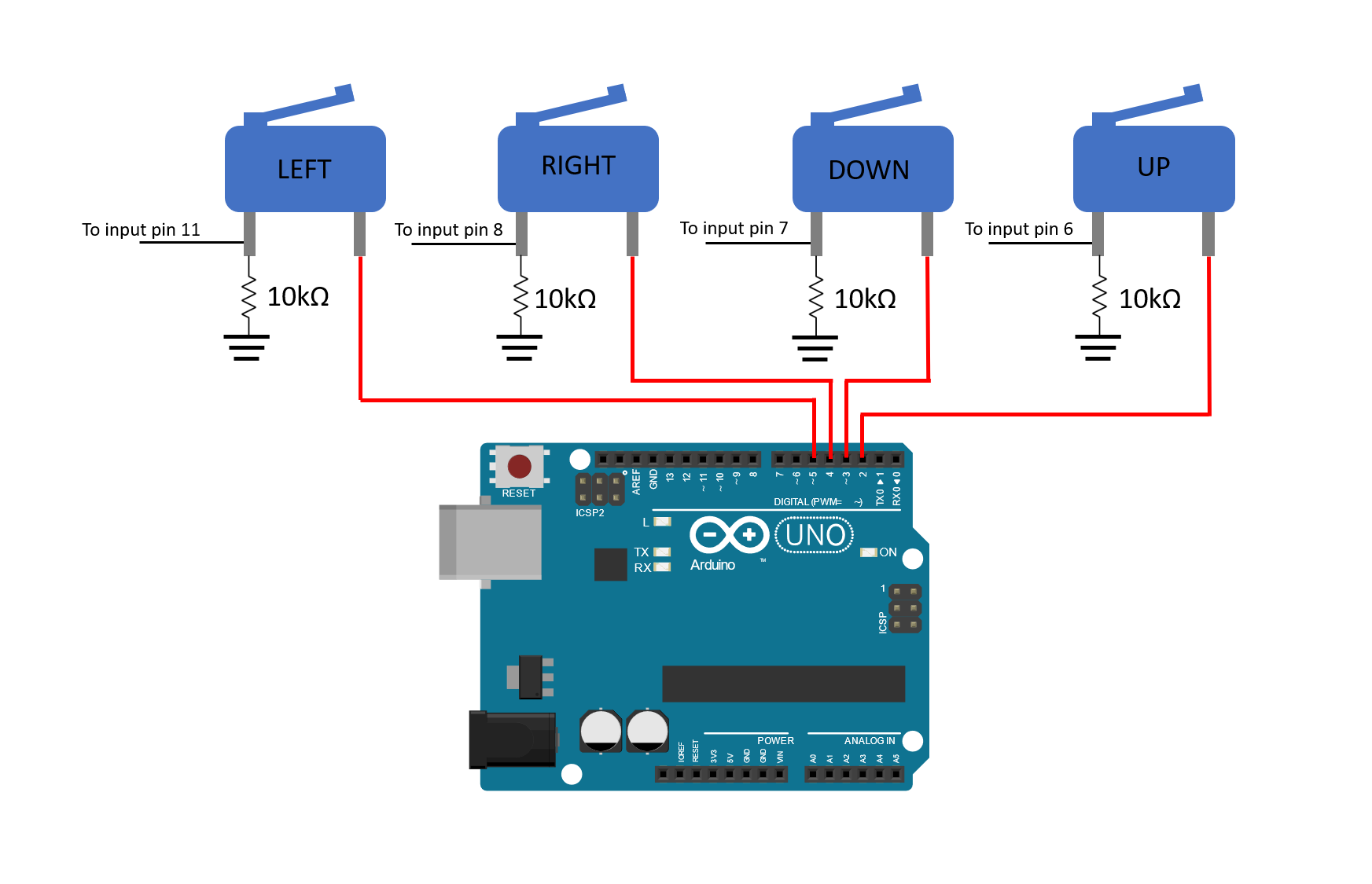
Hopefully you labeled which wire goes to each limit switch. We’re using Uno pins 2-5 as output pins and pins 6-8, and 11 as input pins on the Uno. The wires that go to the input pins of the Uno will need to be routed to a breadboard first so that they can be tied to a pull-down resistor. A schematic is shown below.
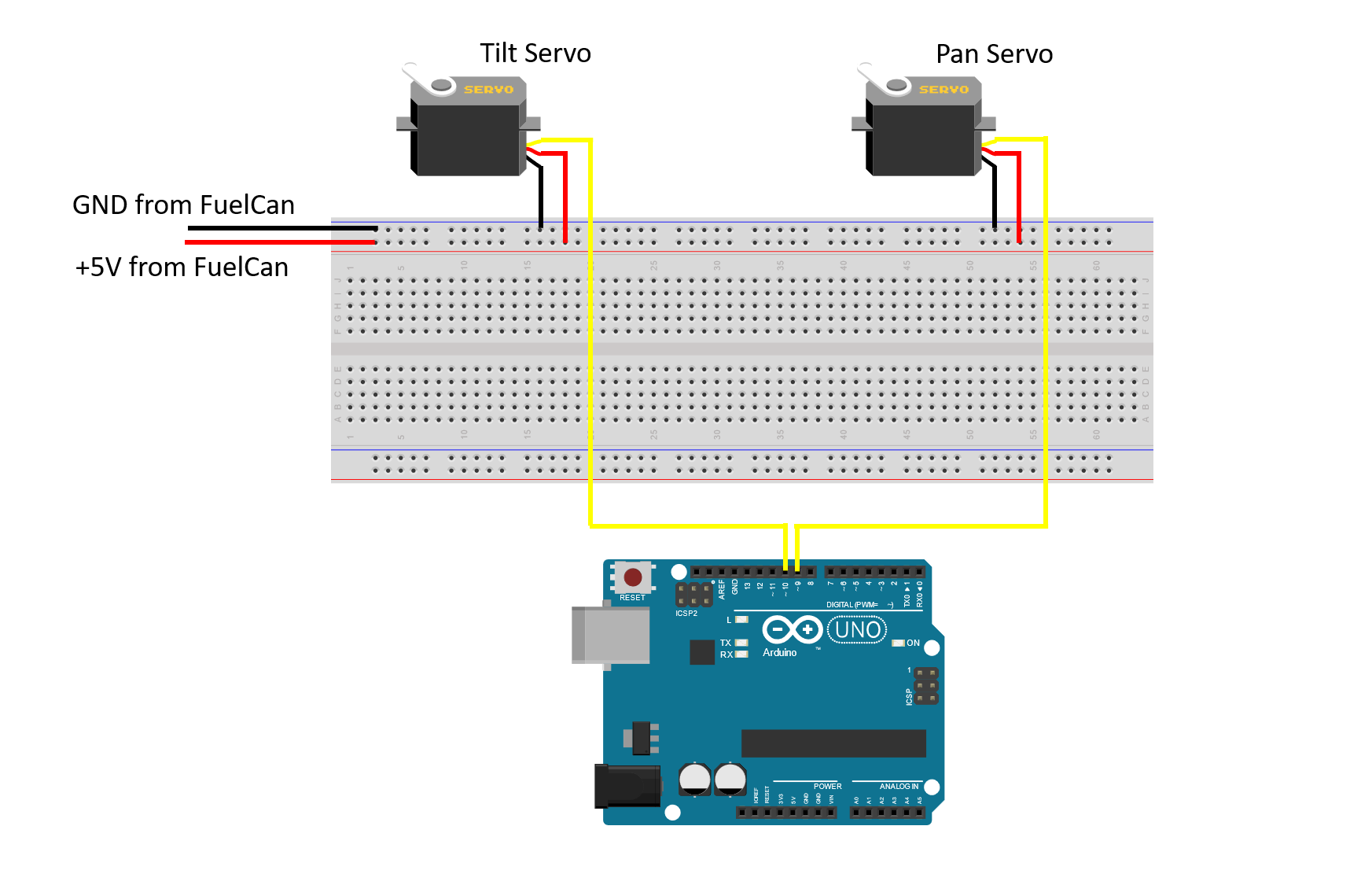
Wiring the Servos
Servo motors typically have 3 wires: power (red), ground (black or brown), and signal (yellow or orange). They have a 3-pin female header at the end of the wiring harness so we’ll need 3 male header pins to connect them to a breadboard. You can either route the signal wire of each servo motor to the breadboard first or tie them straight to the female header on the Uno. We’re going to use pins 9 and 10 since these are PWM channels (marked with ‘~’ on the Uno). The servo used to tilt the camera will be tied to pin 10 and the servo used to pan the camera will be tied to pin 9. A circuit schematic is shown below.
Final Wiring
If you haven’t mounted the Uno onto the prototyping area of the FuelCan, go ahead and do that. I placed the breadboard in the bottom storage compartment to limit the length of the jumper wires. We need to supply GND to the ground rail and +5V to the positive rail on the breadboard. Use the provided banana jack to test-lead clip cables to do so. You will need two male header pins to mount the test-lead clips to the breadboard side. Plug the Type A side of the USB cable into the USB1 receptacle and the Type B side into the Uno’s receptacle. Plug in the Type A to Type A USB cable into a USB port on your computer and the external USB connector of the FuelCan. Power up the FuelCan with the AC-DC power adapter.
Software Logic
Once the wiring is complete and the FuelCan is powered up, we can now load the sketch onto the Uno. The core of this program lies in checking the state of the Digital Input in different directions. When a switch is pressed, the variable storing the servo angle value (degrees) will be incrementally increased or decreased, and that value will be sent to the servo via the servo.write(angle) command.
The sketch is below. When the joystick is moved up, down, left, and right, the camera will tilt up, tilt down, pan left, and pan right, respectively. If yours does not do this, try rearranging the input wires from the limit switches.
#include <Servo.h>

Servo panServo;
Servo tiltServo;

int panAngle = 90;
int tiltAngle = 90;

void setup() {
  panServo.attach(9);
  tiltServo.attach(10);

  // Set Input pins for Joystick
  pinMode(6, INPUT); // Right
  pinMode(7, INPUT); // Left
  pinMode(8, INPUT); // Down
  pinMode(11, INPUT); // Up

  // Set Output pins to supply power to the switches
  pinMode(2, OUTPUT); digitalWrite(2, HIGH);
  pinMode(3, OUTPUT); digitalWrite(3, HIGH);