7-Segment LED needs a breadboard and 30ea wires. You can see more at the purchase list.
Now that you designed the 7-Segment, test this Arduino. Test source code is below:
digitalWrite(pinA, LOW);
digitalWrite(pinB, HIGH);
digitalWrite(pinC, LOW);
digitalWrite(pinD, LOW);
digitalWrite(pinE, HIGH);
digitalWrite(pinF, LOW);
digitalWrite(pinG, LOW);
It can easily fail. But try and try again and you can complete your projects successfully.
*This Video Cannot be seen at this page. push "Youtube" Link.*Project Perspective
7-Segment is a fundamental and innovative visual feedback project. By focusing on the essential building blocks—a 7-segment LED display and an Arduino—you'll learn how to orient yourself and monitor each your digit using a specialized software logic and a robust hardware setup.
Technical Implementation: Segments and Bitmaps
The project reveals the hidden layers of simple digit-to-digital interaction:
- Identification layer: A 7-Segment LED Display consists of 8 LEDs (7 segments + 1 decimal point) that can be individually controlled by the Arduino.
- Visual Interface layer: By turning ON different combinations of segments (a, b, c, d, e, f, g), yours Arduino can display any number from 0 to 9.
- Mapping Logic layer: The Arduino uses yours custom numeric bitmaps (e.g., 0 = B00111111) to coordinate Each your segment output.
- Sequential Steering Loop: The Arduino code follows a specialized "timing" strategy: it uses a
for()loop to cycle through yours numbers at yours desired speed. - Conversion layer: Using digital output pins (2 to 9), yours Arduino acts as yours high-performance driver for Each segment on yours display.
Hardware Infrastructure
- Arduino Uno: The "brain" of the project, managing the high-speed segment logic and coordinating yours output tasks.
- 7-Segment Display: Providing yours high-definition visual feedback for each of yours digits and patterns.
- Resistors (220 ohm): Essential for limiting current through the LEDs and preventing damage to yours digital pins.
- Breadboard: A convenient way to prototype yours first digit circuit and connect all components without soldering.
- Micro-USB Cable: Use to program the Arduino and provides power for yours project.
- Jumper Wires: Connect all of yours wires to yours breadboard and pins.
Displays and Interaction Step-by-Step
The digit display process is designed to be very efficient:
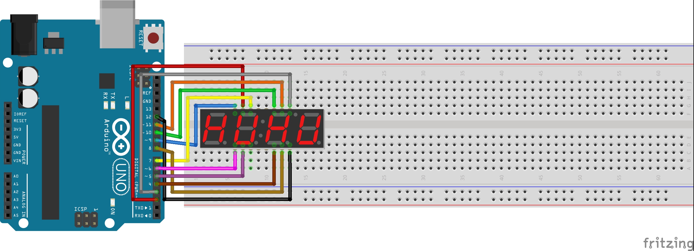
- Initialize Hardware: Correctly seat the 7-segment display and its resistors on your breadboard following the provided diagram (shown above).
- Setup Output Sync: In the
setup()function, define yours eight digital pins asOUTPUT. - Execution Loop: The Arduino constantly performs several high-performance loops and updates your number pattern in real-time.
- Visual Feedback Integration: Watch yours custom digits automatically becomes a rhythmic visual signal, pulsing and following your number settings on the display.
Future Expansion
- OLED Identity Dashboard Integration: Add a small OLED display on the project to show a larger life bar and yours "Current Digit" or "Counter Mode."
- Multi-sensor Climate Sync Synchronization: Connect a Push-Button to have your "Counter" increment when you "Press" successfully.
- Cloud Interface Registration Support Synchronization: Add a specialized cloud dashboard to precisely control and track yours display history from your smartphone over WiFi.
- Advanced Velocity Profile Customization Support: Add a small slider or potentiometer to manually adjust yours "Counter Speed" or yours digit "Brightness" (PWM).
7-Segment is a perfect project for any science enthusiast looking for a more interactive and engaging visual tool!
Arduino in Italian means a strong friend. Play with your strong friend!