8 Pieces of Daisychained WS2812B 8x8 RGB LED Matrix
This project began with an overflowing sense of patriotism during National Day week, combined with the desire to create new content for my Youtube Channel. Suddenly, I remembered I had some 8x8 RGB LED Matrix panels that I bought last year and left sitting in a box (not collecting dust, just waiting for the right moment!).
So I decided to dust them off and combine them with an 8x24 Matrix panel that I had previously daisy-chained during the past year-end holidays (if you're interested in connecting that panel, you can click here for more details). Once combined, I had a large 16x32 Matrix display ready for higher-resolution graphics.
Technical Challenge: When the Software Doesn't Cooperate
In engineering, controlling a massive number of LEDs (512 in this case) typically involves tools like Glediator, a popular software for LED Matrix Control via Serial protocol. However, this path was not a bed of roses. I tried using two Arduino UNOs, and even an Arduino MEGA, changing USB ports on the PC, and even installing x64 RXTX comms for Java from multiple sources to fix connectivity issues. But ultimately, the program still couldn't detect the COM Port.
After expending so much effort on debugging software that I nearly gave up, I decided to stop relying on off-the-shelf software and revert to the most basic yet powerful method.
Manual Engineering Solutions
I had a fleeting thought: should I just buy a pre-built 16x32 panel? Or should I use the Adafruit Matrix Library? But it seemed my existing hardware (which often consists of Addressable LEDs like WS2812B) wasn't very compatible with those libraries in my current setup. So I challenged myself again: "We just want to display simple shapes (like a flag), how hard could it be?"
The answer: Challenging in terms of patience!
I opted for the FastLED Library, which is central to controlling Addressable LEDs at the Register level, by programming the color for each LED individually, also known as Manual Pixel-by-Pixel Mapping.
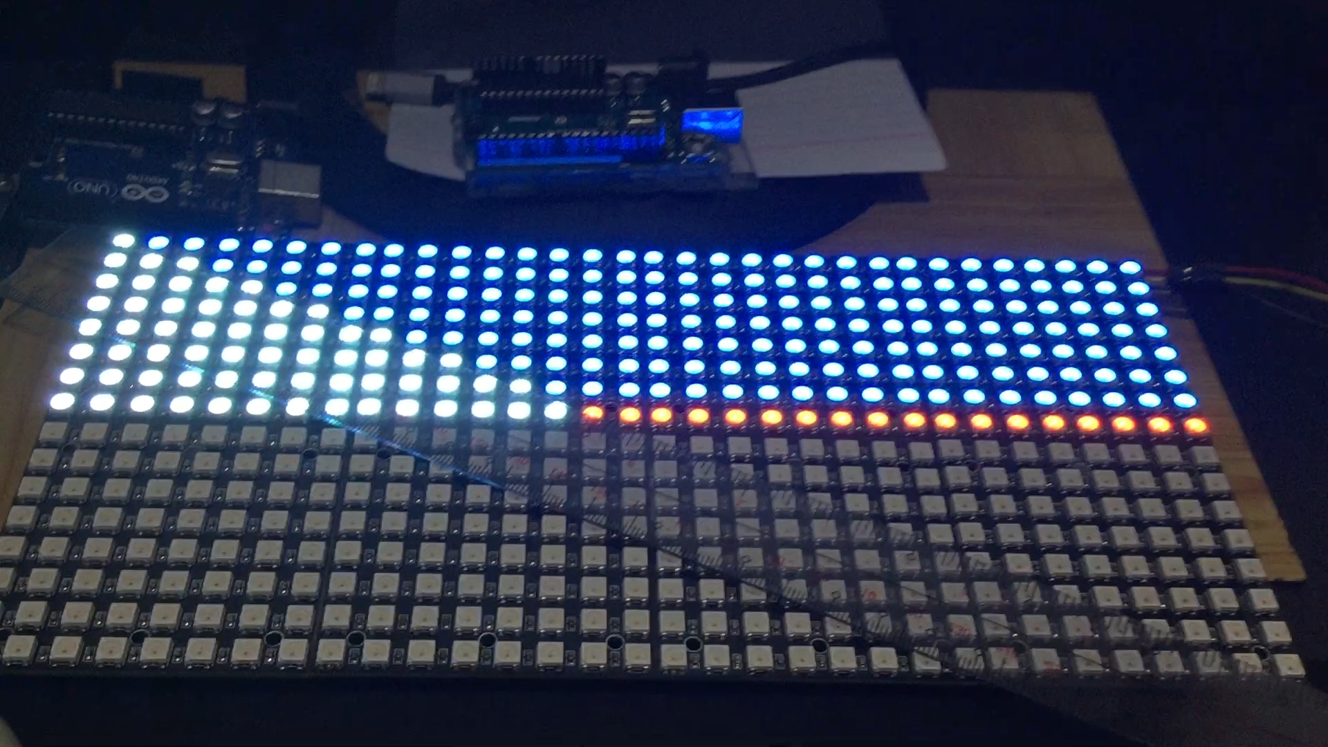
In terms of Code logic, I had to manage the CRGB leds[512] color Array by assigning each LED's Index to match the physical layout of the panels. Since I daisy-chained panels of different sizes, the pixel order didn't follow a natural linear sequence. Therefore, I had to use Coordinate Mapping and paint colors into the code line by line, for example:
- Blue pixel range for the top stripe
- Red pixel range for the bottom stripe
- Calculating the area for the white triangle and the position of the yellow sun
It truly was a "manual labor" approach in the world of coding.
Follow My Work (Social Media Links):
If you enjoy Hardcore Maker projects like this, please follow me on: