1. How does it Work?
The choice to go up or down in order to follow the light is done in a very simple way. There are four LDR two up and two down. Arduino reads the analog value of all LDR, if the average of the two upper values is greater than the two lower the light is up so the angle of the microservo is incremented otherwise decremented.
2. A Little Clarification
Since the average is not a fixed number, as you can see in the code, a threshold is used. In this way the angle is changed if and only if the two averages are widely different.
const int threshold = 50;
[.....]
down_average = (A0_val + A1_val)/2;
  up_average = (A2_val + A3_val)/2;
  diff = abs(up_average-down_average);
  if ((up_average > down_average) && (diff > threshold))
    {
     if (val < 180) //if different from max val
       {
       val++;
       myservo.write(val);
       }
    }
  if((down_average > up_average) && (diff > threshold))
    {
    if (val > 0) //if different from min val
      {
      val--;
      myservo.write(val);
      }
    }
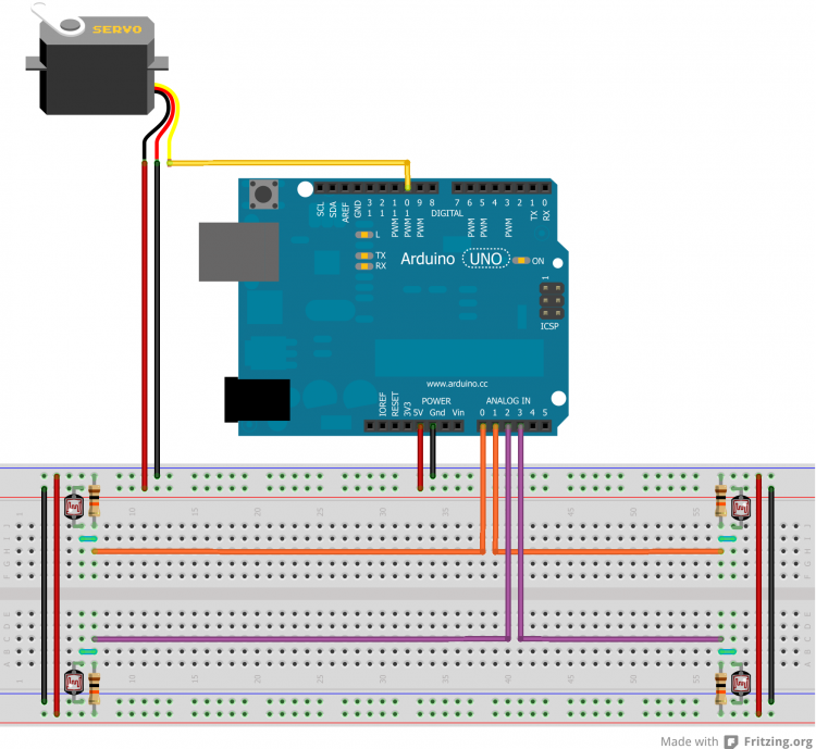
3. The Circuit
Make the circuit below!
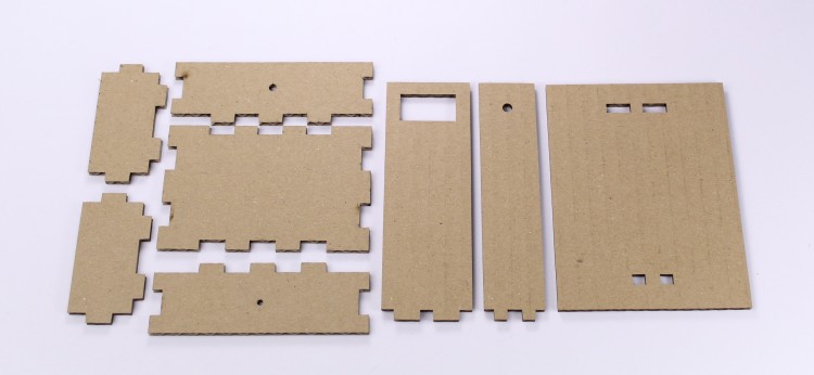
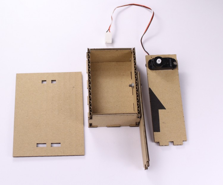
4. Print & Cut
Download the attached file, print it, glue it on the cardboard and cut all the pieces for yours light follower. You should obtain something like this.
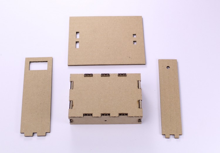
5. Mount the Base
Mount the breadboard base in this way. Glue it if necessary.
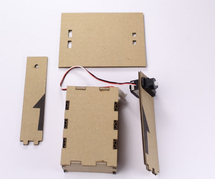
6. Mount the Servo
Mount the servo like below. Screw it for more stability.
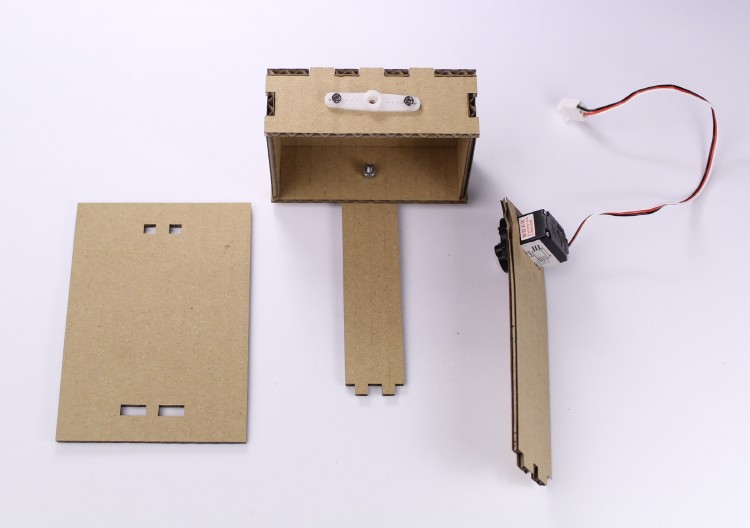
7. Mount the Bracket
Mount the bracket in this way.
8. Mount the Servo Gear
Mount the servo gear. Screw it in this way.
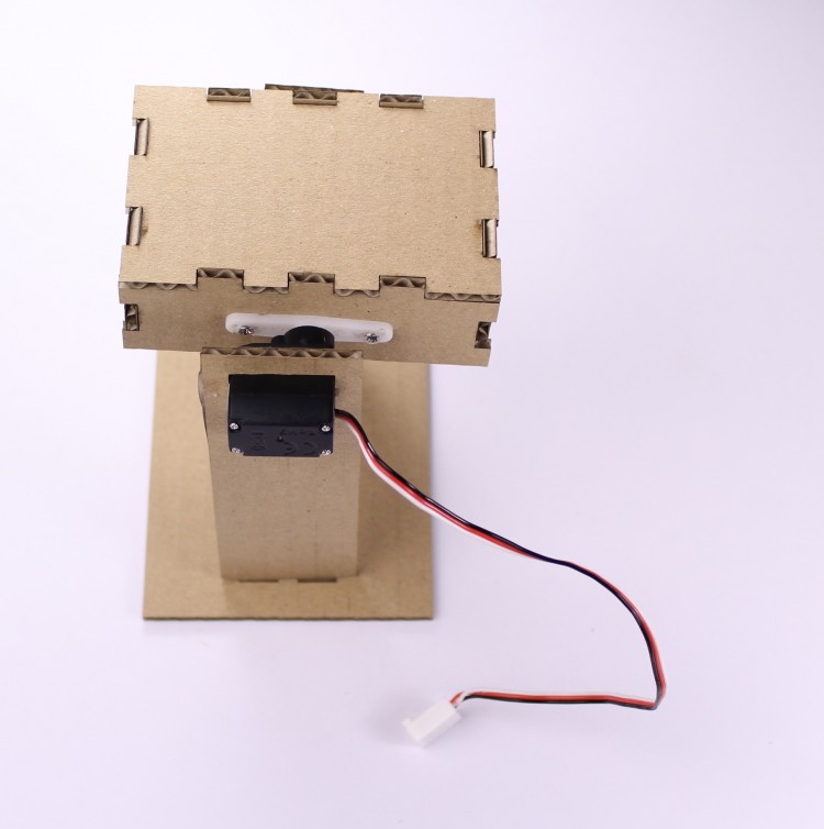
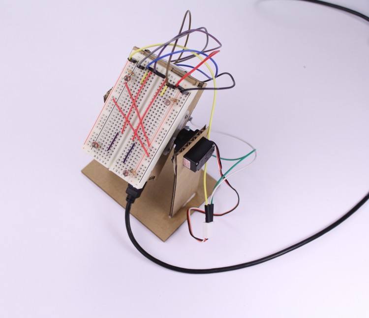
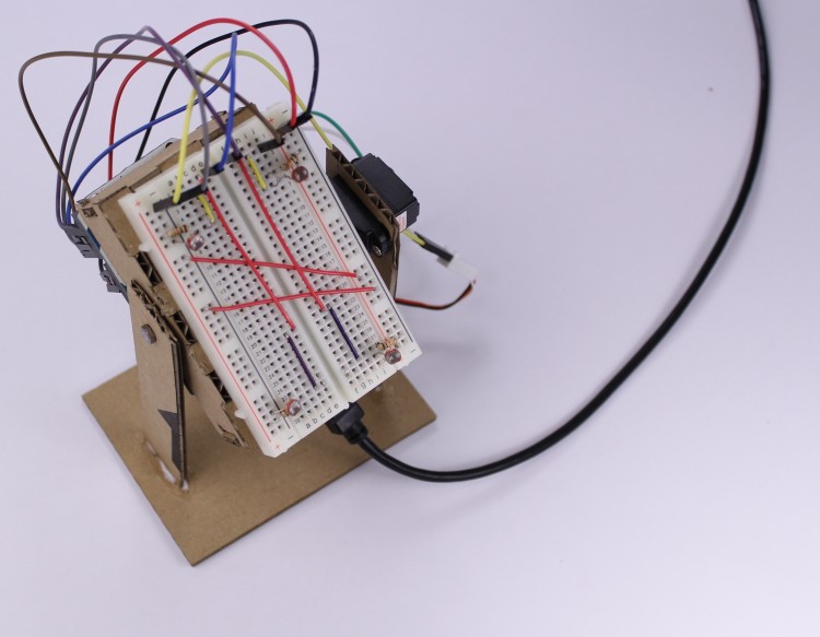
9. Put all Together
Put all together. You should obtain something like this
10. Glue the Breadboard on the Base
Glue the breadboard on the base. You can use the biadhesive tape of the breadboard.
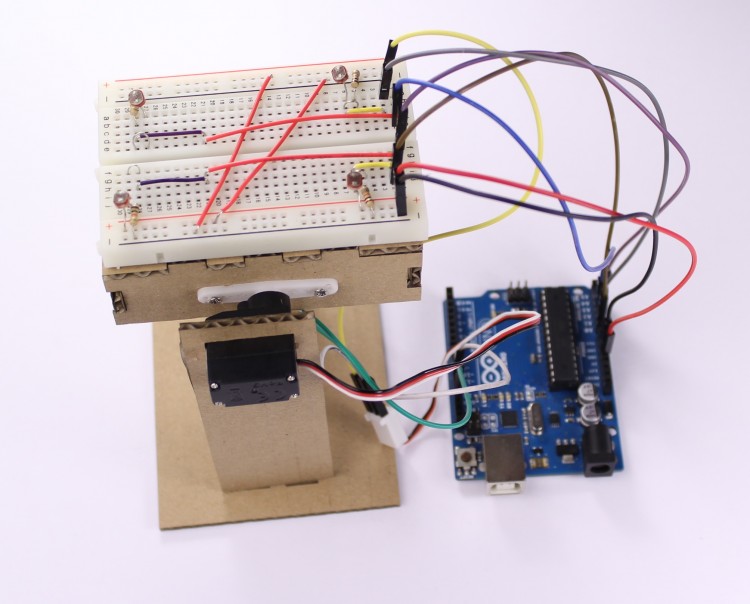
11. Screw Arduino
Screw Arduino on the back of the base.
12. Well Done
Well done. Now you have all the necessary. Download the code on your Arduino and enjoy with your light follower!
EXPANDED TECHNICAL DETAILS
Phototropic Autonomous Movement
This robot is designed to "seek" the brightest light source in a room, mimicking the behavior of plants or insects.
- Differential Sensing: Uses two Light Dependent Resistors (LDRs) mounted at the front of the robot, separated by a physical divider. The Arduino compares the analog readings from both sensors.
- Steering Logic: If the left sensor reads more light, the Arduino turns the right motor faster; if the right sensor reads more, it turns the left.
Hardware Architecture
- Drive System: Driven by two DC gear-motors via an L293D motor driver.
- Simple & Effective: This is a classic foundational project for understanding analog feedback loops and basic PID-style control without complex math.