title: "Developing an Orientation Sensing Sensor with ADXL345 and Arduino Nano"
Introduction and Project Origin
The genesis of this project stemmed from a desire to build a "Digital Hourglass," a popular project within the Maker community. However, I encountered a problem when I discovered that the original project files and specified components didn't match what I had on hand. Specifically, the original project used an ADXL343 accelerometer, but my component inventory only contained an ADXL345.
Although both sensors appear similar, directly using the original code wasn't as straightforward as I expected. I therefore decided to rewrite the program (fork it) specifically to support the ADXL345. For more accurate orientation detection, I studied the technical documentation (Datasheet) and an Application Note from NXP (AN3461), which explains the logic behind switching between portrait and landscape screen modes in smartphones. This served as a crucial foundation that I applied to this project.
Hardware Details and Circuit Design
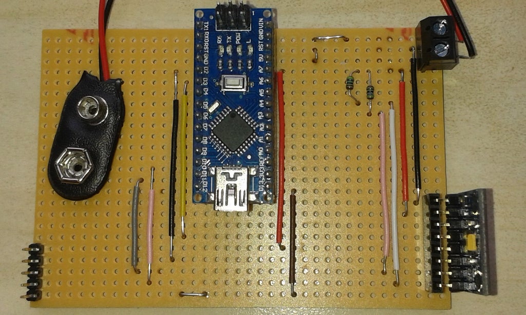
The board used in this project is a further development of a previous project, with its core components consisting of:
- Arduino Nano: A small yet powerful main processing unit sufficient for sensor signal processing tasks.
- ADXL345 Accelerometer: A 3-axis (X, Y, Z) MEMS accelerometer with a high resolution of up to 13-bit, communicating via the I2C protocol.
- MAX7219 Dot Matrix Display: An 8x8 LED Matrix display module used to show the direction detected by the sensor.
Key Connections:
- ADXL345 (I2C): Connect the SDA line to Pin A4 and SCL to Pin A5 of the Arduino Nano. 4.7K Ohm pull-up resistors must be connected to VCC to maintain data signal stability.
- MAX7219 (SPI-like): Uses three main signal lines: DataIn (Pin 11), CLK (Pin 13), and Load/CS (Pin 10).
- Board Structure: There are 11 traces on the top layer and 20 track breaks on the bottom layer to separate signals.
Engineering Tip: From practical use, I found that using a right-angle connector for the sensor would allow for more natural device rotation, rather than having to flip the board back and forth as is currently the case.
Software Logic Analysis
The core of this project is transforming raw acceleration data into orientation awareness.
1. Unit Conversion
One of the initial problems I encountered was that the Adafruit Library outputs values in m/s², but the calculation formulas from the Datasheet require values in g-force units:
- $0.5g \approx 4.9 , m/s^2$
- $0.4g \approx 3.9 , m/s^2$
I therefore had to convert these values within
ifconditions to align with physics standards.
2. Offset Calculation
The code defines values like #define zero_x 1.569 (including for the Y and Z axes) to serve as a "Zero-G Offset," or initial calibration. This is to subtract potential inaccuracies caused by the sensor not being perfectly level with the Earth's surface.
3. Orientation Detection Algorithm
The program checks the relationship between all three axes to determine the device's orientation, using the following criteria (referenced from the loop function):
- Top: When the Z-axis acceleration value is less than 0.5g (flat), the X-axis is greater than 0.5g (tilted down), and the Y-axis is stable.
- Bottom: When the X-axis is negative, less than -0.5g.
- Right/Left: Uses similar detection logic but focuses on the Y-axis instead.
4. Display Output
When any orientation condition is met, the program calls the rotate_display(char my_direction) function to instruct the MAX7219 chip to illuminate LEDs on the Matrix as a symbol representing that direction via the lc.setLed() command.
Required Libraries
For this project to function, you need to install the following Libraries via the Arduino Library Manager:
- Adafruit_Sensor: Base Library for Adafruit sensors
- Adafruit_ADXL345_U: For retrieving acceleration values from the ADXL345
- LedControl: For controlling the MAX7219 display
- Wire: For I2C communication (included with the Arduino IDE)
Conclusion and References
This project demonstrates the critical importance of understanding "measurement units" and "Datasheets" in embedded engineering. The transition from ADXL343 to ADXL345 was not merely a sensor name change, but an adaptation of logic to align with the physical characteristics of the device.
Technical References: