The goal of this project was to make a device that could regulate the air/fuel mixture of a mechanical LPG (OHG)mixer in my car.
For a better fuel economy it's best to stay as close as possible to the optimum air/fuel ratio.
In the past there where a few commercial available products like IMPCO fuel controller , but there is no market for these things anymore , so nothing is available anymore.
They all work differently and rather slow , so I decided to try make one myself.
Since most LPG mixers can be adjusted only so far , they are not very precise and mostly on the rich side , which is not so good for fuel economy.
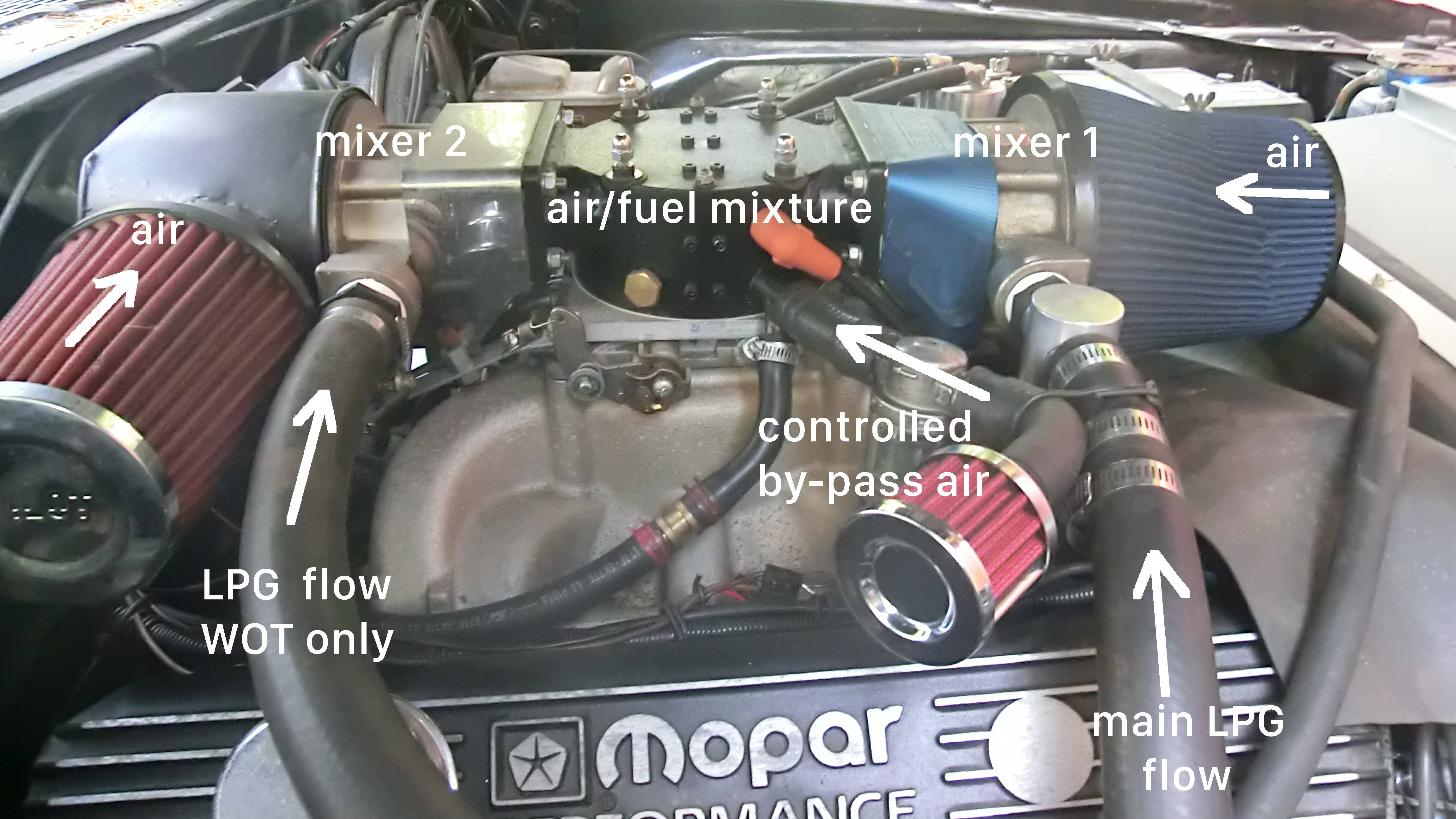
The idea was to lean out the mixture by introducing air after the mixer , but before the throttlevalve.
Air that by-passes the mixer(false air) , should lean out the gas mixture.
This idea turned out to be very effective.
I just need to control the by-pass air very precisely to obtain the optimum air/fuel ratio.
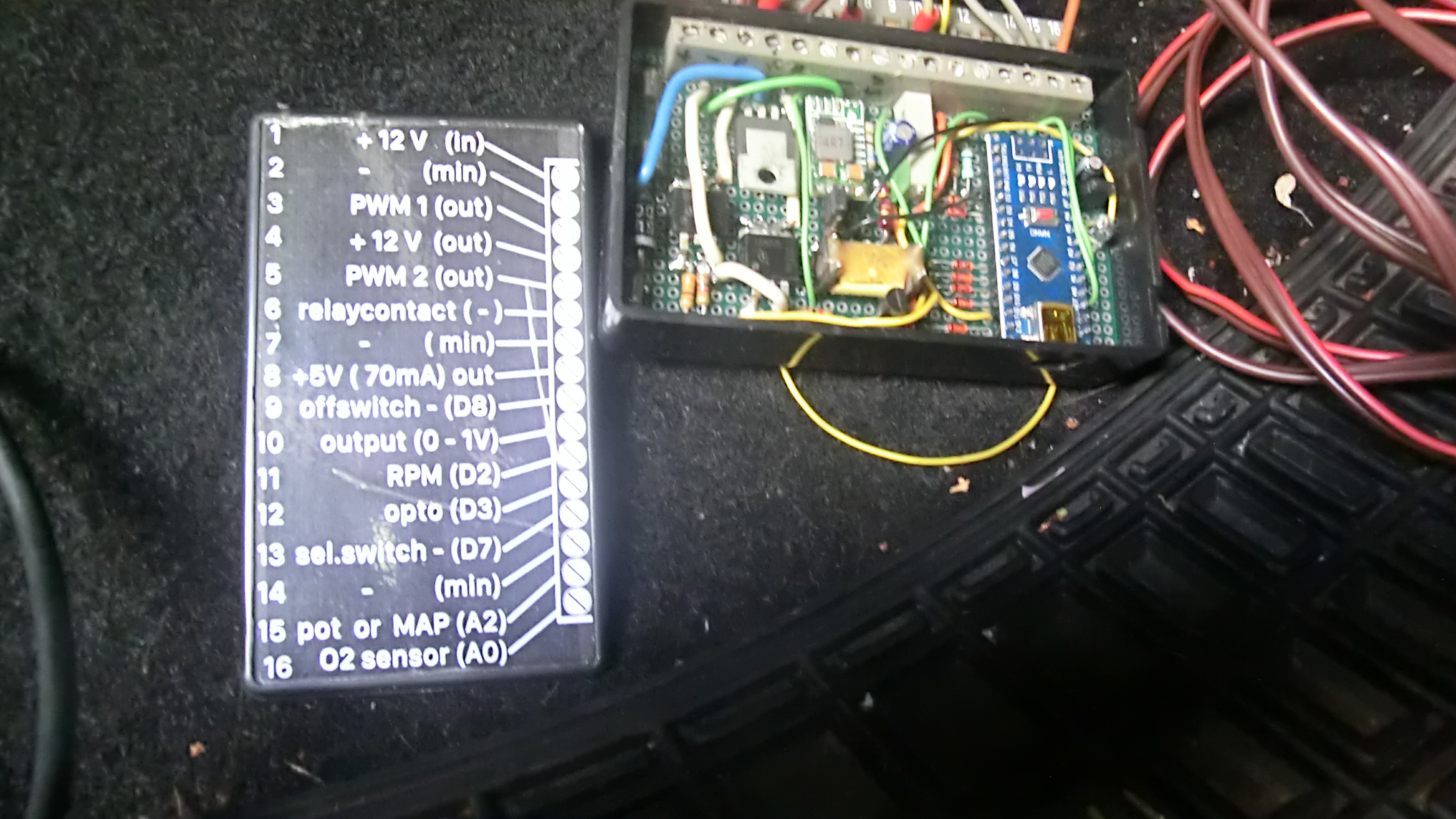
There a Arduino Nano comes in play , it's perfect for something like this.
I already made a programmable ignition system with the Nano , that introduced me to the Arduino world.
By back-engineering a Arduino ignition system I found on the net , I learned all about Arduino and coding , but that is a topic on it's own.
The Arduino ignition is running for 6 years now , so I have some confidence in the reliability of a Nano.
For this project I used mainly old computer parts and stuff I had laying around.
To control the by-pass air I used a Bosch stationairy valve I found on a junkyard.
To control the valve I used a Arduino Nano.
To control the Nano I used a narrow-band lambda sensor in the exhaust.
The Narrowband O2 Sensor (Lambda Zirconia Physics)
A standard Bosch 1-Wire or 4-Wire Oxygen Sensor sticking out of a car exhaust does not output "Rich" or "Lean."
- The Zirconia ceramic element inside the sensor generates a chaotic, non-linear raw analog voltage!
0.1 Volts = Extremely Lean (Too much air, the engine runs hot and blows up).0.9 Volts = Extremely Rich (Too much gas, fuel splashes out the exhaust).0.45 Volts = Stoichiometric Perfection (14.7:1 Ratio).- The Arduino Analog Pin
A0violently reads this voltage exactly as the 1000°C exhaust gas hammers the sensor.
Since I already have two lambda sensors in the exhaust , one on each side , for many years now , and two O2 gauges to read out the sensors , I have a pretty good idea of what's going on in the engine.
I used one of the sensors as input for the Nano. Sensor output is between 0 and 1000mV , so it can go directly to a Analog input.
I used 1Mohm resistor to ground to dampen input noise.
The Actuator Control Loop
First I had to figur out how I can control this Bosch stationairy valve.
The valve basically exists out of two elektromagnetic coils opposite to each other. One coil opens the valve , the other coil closes the valve.
If you power them both you can get any in between setting you want.
The valve has 3 connections , one common and one for each coil. The valve is 12V and draws about 1A so I used two logic level FET's to controle it.
A opposite PWM signal from the Arduino steers the two FET's. If one goes up the other goes down , and vica-versa.
To get rid of the annoying sound of the 980Hz standard frequency , I used a library file called "GYVER" which unfortunately is russian , but it does the job perfectly.
It can set the frequency to any desired level , so after some testing I came to set it at 8000Hz , out of my hearing range.
To move the valve I just need a number between 0 (closed) and 100 (open) , and it will automatically move to that position.
A FOR loop moves the valve in steps of 1% to ensure smooth movement.
In the code it is a separate section just for valvecontrol.
The Execution Trap: The Oxygen Sensor is 250 milliseconds "Delayed" behind the physical engine intake. If the Arduino adjusts the valve heavily, it will over-correct into a terrifying oscillation loop, stalling the engine instantly.
How to process the O2 signal?
Since the output of a narrow-band lambda sensor is fluctuating all the time , it's always above or below 500mV but never at the desired 500mV , I have to stabilize the sensor readings a bit.
I decided to use two averages.
One short term average (500ms) , and one long term average (10sec) , to stabilize the sensor readings.
The short term average is the average of 10 sensor readings. I limited the loop speed to 50ms , so every 50ms I get a new reading.
I put the readings in a array of 10 , then devide by 10. When the array is full (10 numbers) , the first reading will be replaced by a new reading , then the second , then the third etc etc.
So it's a average of 500ms refreshed every 50 ms.
This way I get a stable enough reading to work with.
The long-term average is 20 times the outcome of the short-term average after 500ms. So 20 X 500ms = 10 sec. It's refreshed every 500ms.
Since the code is not very complicated or long I think it will explain itself.
There are a few things in the code just to give me feedback what is going on while driving , so I could improve the code on that.
They are not necessary to run the program.
The most usefull is that I can see the valve movement , so I can see how it's reacting to the software.
Second usefull is to see what the long-term average is doing , it should stay to 500mV as close as possible , and it does.
I added a 6-way selector switch to choose what I want to see while driving.
I used a second O2 gauge , which is basically a 0 to 1V voltmeter , to display it on.
Since they are narrowband gauges even they are not available anymore.
Today it's all wideband so that would be the next project , but this concept would still work the same.
The response time is RPM dependant and is between 400ms and 100ms. There was no benefit in going faster than 100ms , so I limited the speed to 100ms.
In my case that is 2400RPM , above that the response time stays at 100ms.
For the RPM count I used the Hall sensor from my ignition system , but it will still work without a signal.
This device is purpose built for a 512cu dodge engine on LPG , but I see many more applications , even gasoline carburetors could benefit from this , just need a air inlet in the right place.
Between the venturi and the throttlevalve.
There is one downside to this method and that is there is a limit to the max RPM's it is effective to , because the size of the by-pass valve is limited.
This engine uses a massiv amount of air but sofar it is effective to about 3000RPM , perfect for everyday driving.
It's not intended for WOT use anyway.
The amount of effectiveness is also dependant on how close the base mixture itself is , how closer to the right value the more effective it is.
It also depends how big the engine is , how smaller how more effective. Since most engines are smaller than 512cu it will be alright I guess.
By using a narrowband sensor I still will be stuck to a 14.7 / 1 ratio (for LPG around 15.5 / 1) , but it's close enough for me.
I am still amazed myself on how good this thing works.
All in all a nice gadget for everyday use.
Combustion Chamber Base Parts
- Arduino Nano/Uno (To reliably control the valve and process the analog sensor logic).
- Logic Level MOSFETs (For driving the 12V, 1A Bosch stationary valve coils).
- Bosch or Generic Narrowband Exhaust O2 Sensor (The 1-wire model is easiest, but requires mounting in an intensely hot exhaust manifold to function!).
- Bosch Stationary Valve (Actuator for controlling bypass air).
- (DANGER: This logic directly controls highly explosive compressed Liquid Petroleum Gas (LPG) engines. Do NOT deploy outside on public roads without extreme safety testing to prevent throttle jamming!)