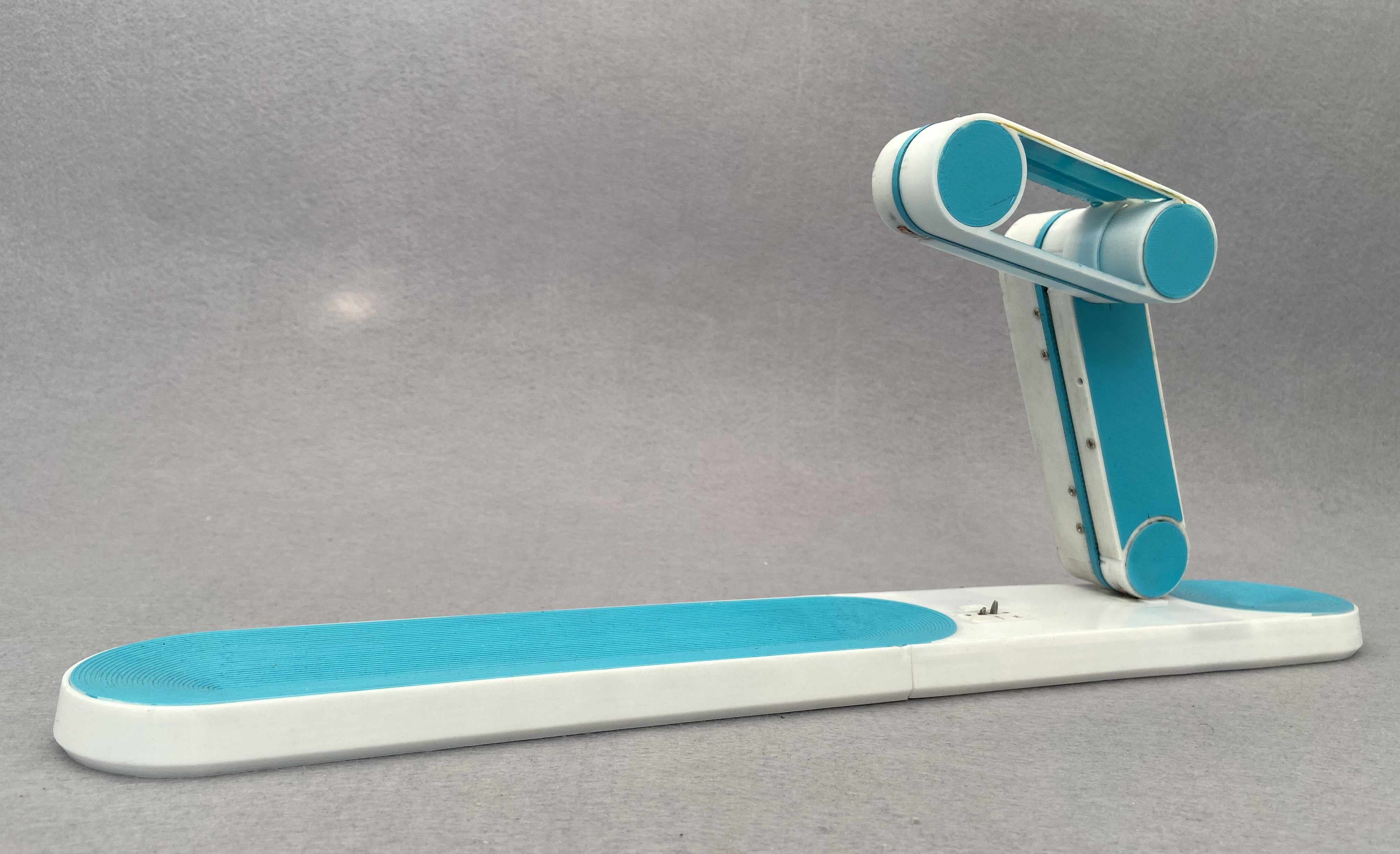
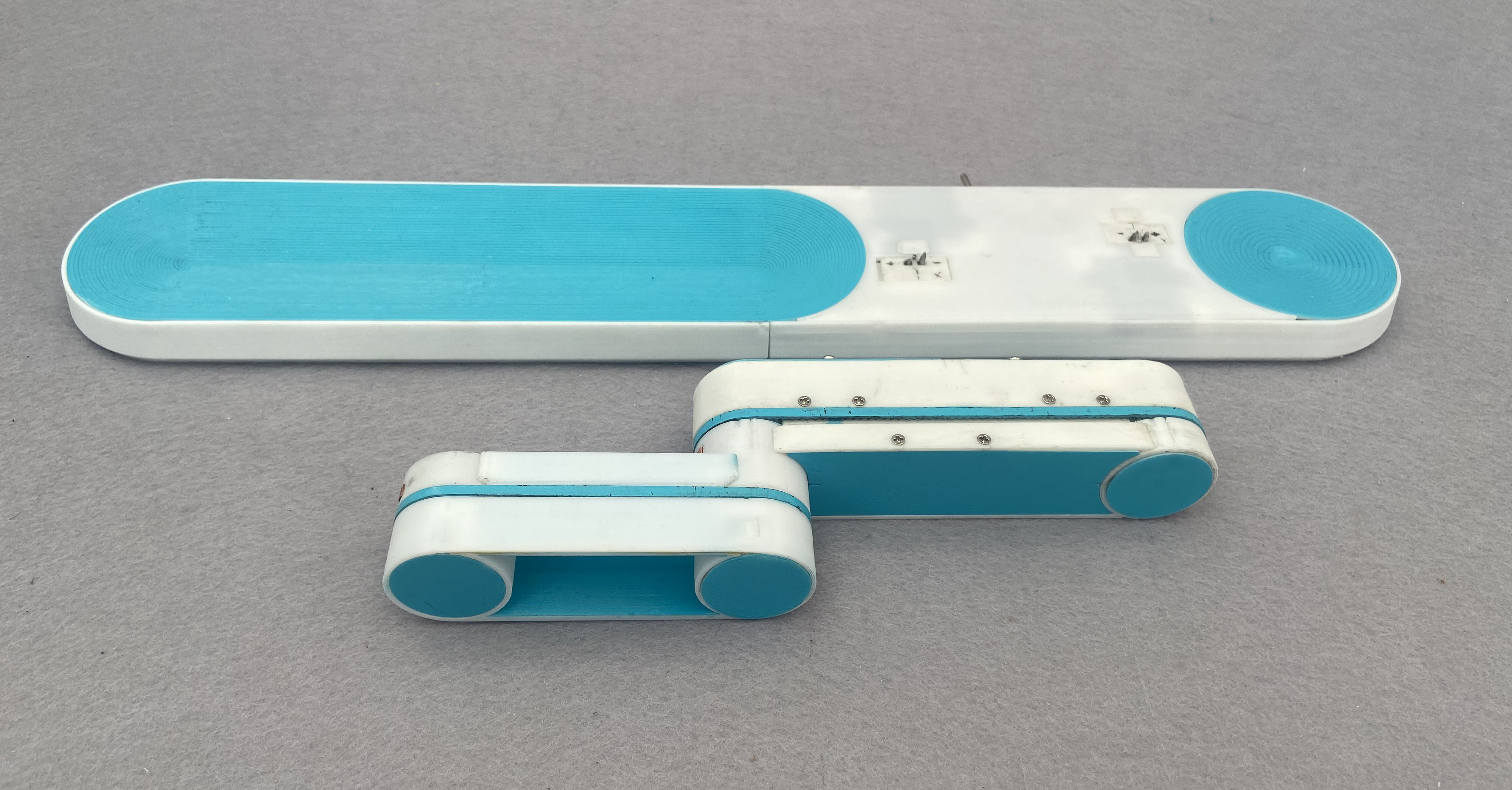
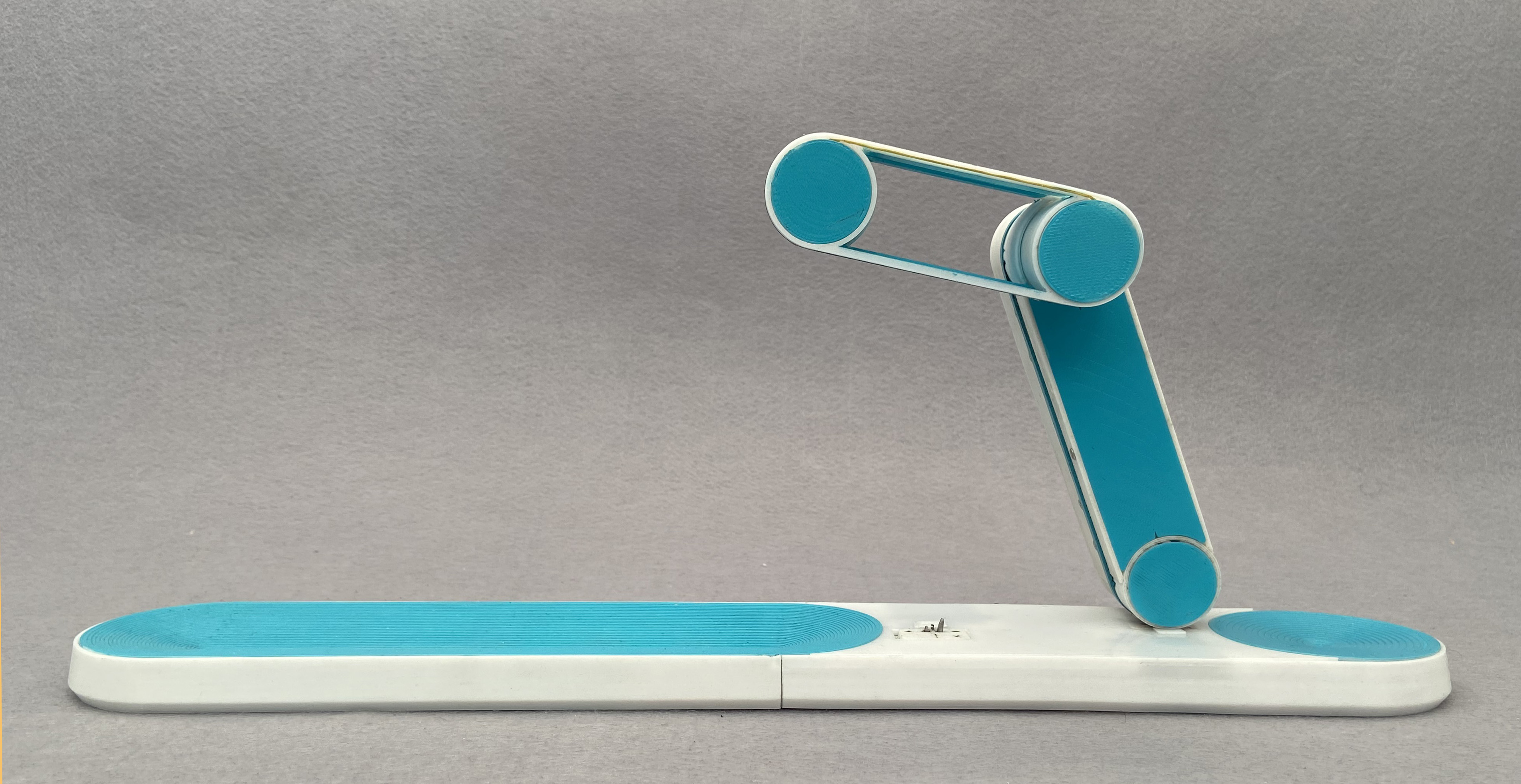
Akurobatto is the continuation of my quest to have a clock with arms that balance on an edge. The first of the series being the edgytokie which had shifting arms but had a major drawback of the hour and minute arms being same and were hard to differentiate. To overcome that limitation I set out to make one where there were arms with different sizes. I achieved that by having arms that could unlock themselves from the base and flip over.
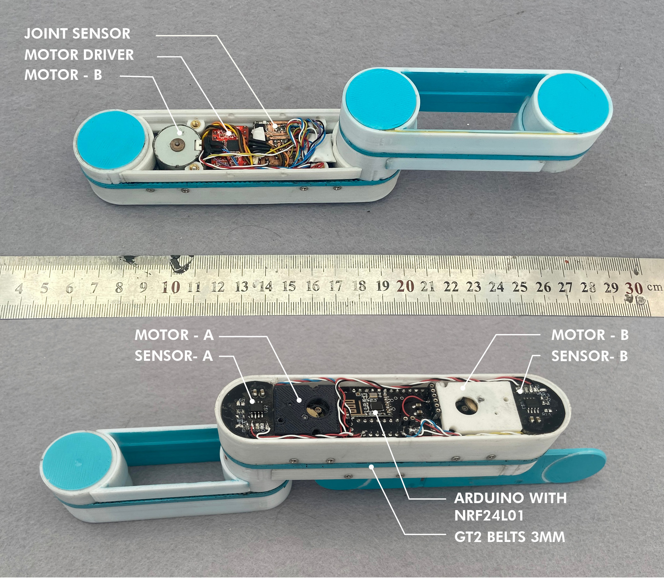
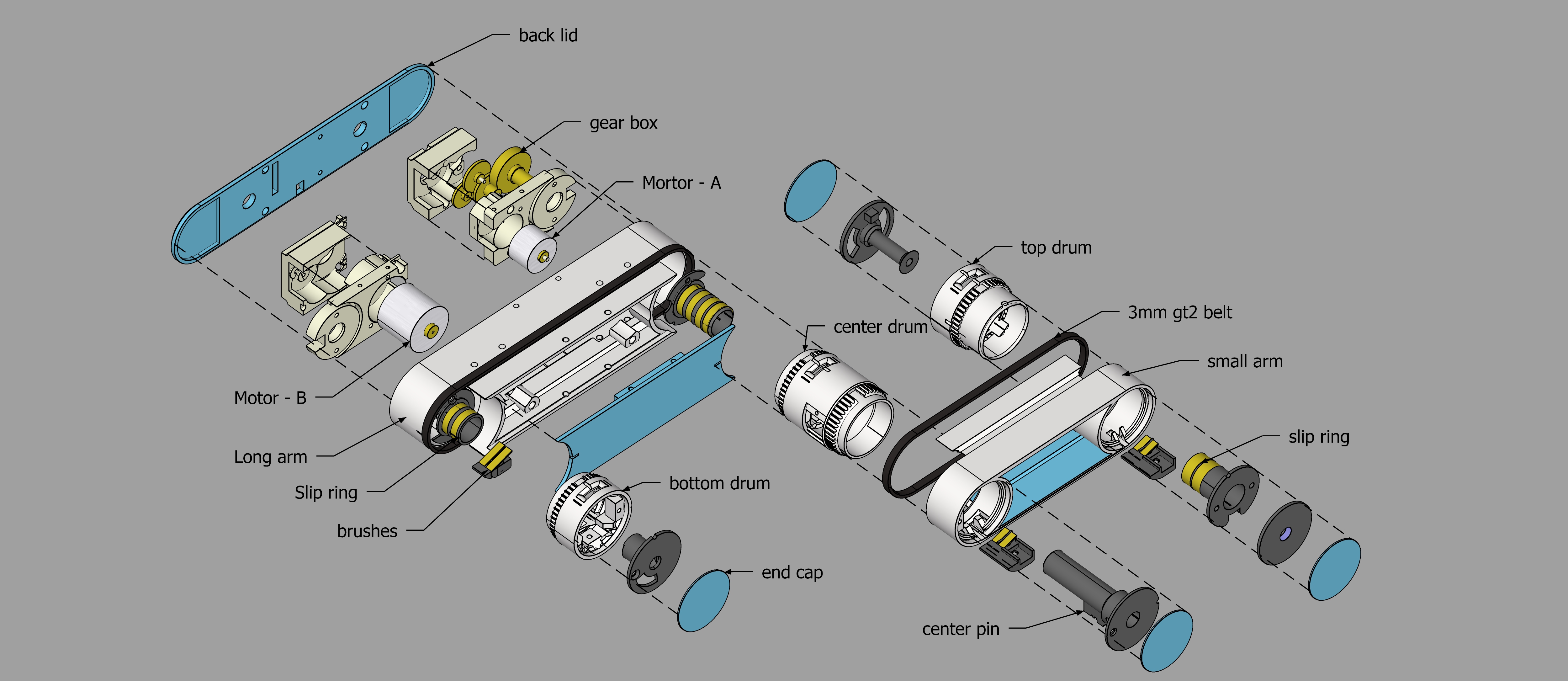
The clock consists of the tops arms and the bottom base. The long arm contains 2 stepper motors, The arduino and the stepper drivers. The Stepper motors although being small consist of a gearbox pulled out of big servo motors. This gives them enough torque to lift the arm. Motor - A is directly linked to pivot of the small arm and rotates it directly. Motor - B is rotates the bottom drum which is linked with belts to the central drum and top arm. If the arm is anchored with the bottom drum then the arm rotates about the bottom drum.When it is anchored to the top drum the arms pivot around the bottom drum via the belts. The arms can anchor to the top, center and bottom drums depending on what kind of movement is required.
The drums have a small magnet mounted on the pivot. The angle of the magnet is sensed using a As5600 rotary sensor which gives the angle feedback to the arduino about the arm location. This avoid unnecessary crashes into the base.
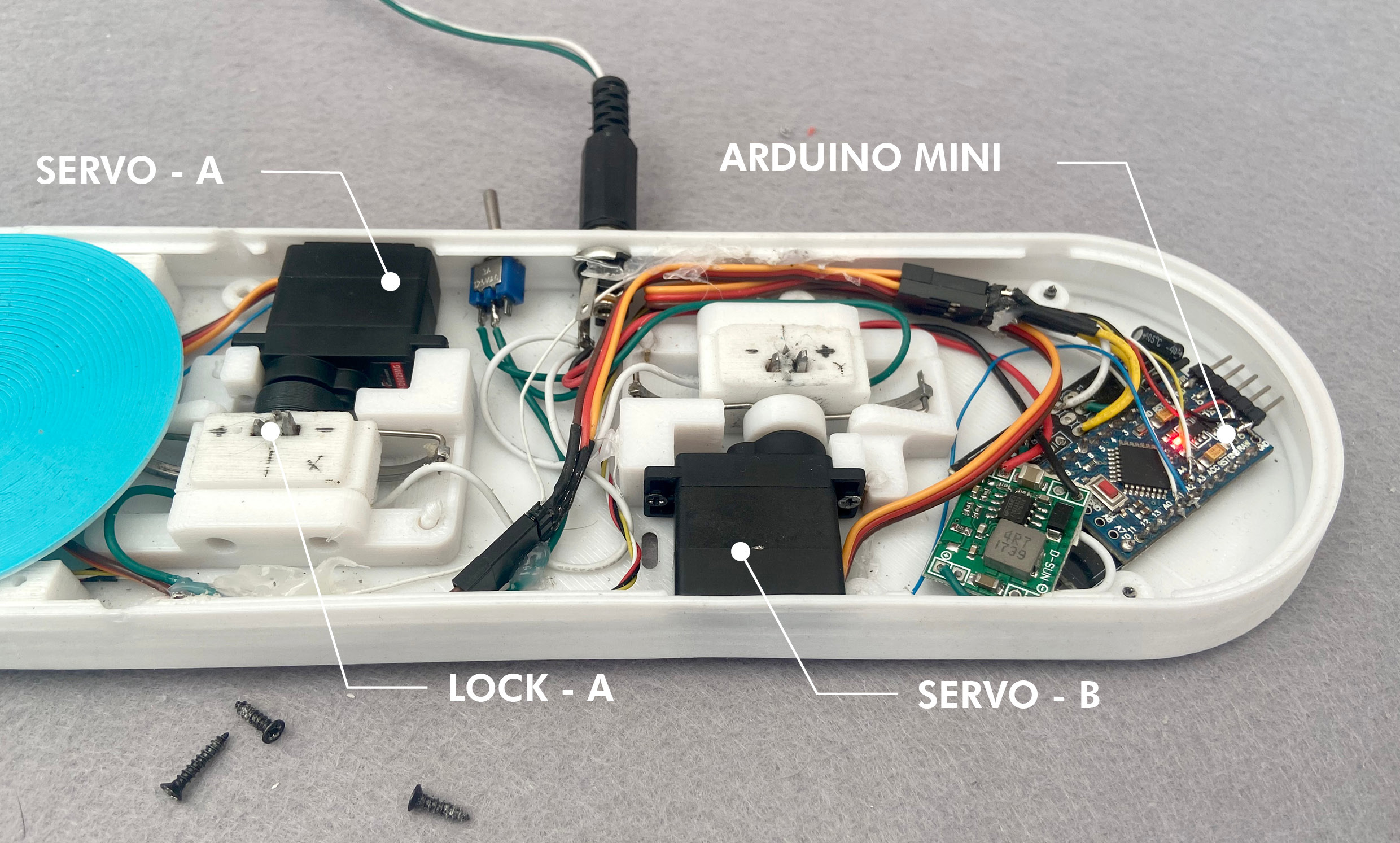
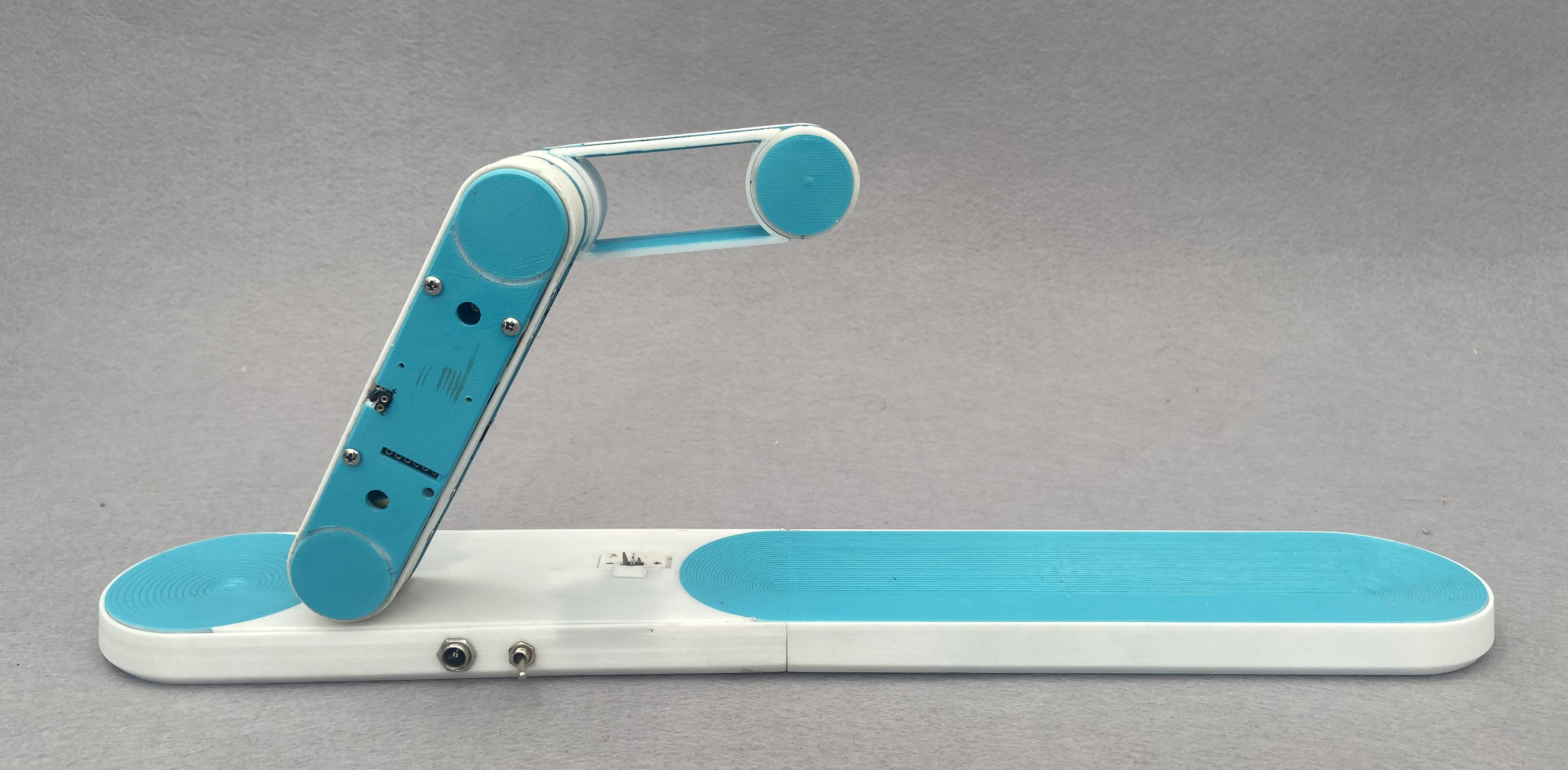
The base consists of two servos which act as the anchors to the arms as well as provide power to the arm. The servos consist of two metal hooks which power the arms with copper clips in the top bottom and center drums. The arms and the base communicate wirelessly using nrf24l01 radio modules. The arms contain the master arduino which does the heavy lifting and sends command to the base to open or close as needed.
The tricky part was power distribution though rotating joints. The power is run though diy slip rings and brushes on every rotary joint. Developing reliable ones out of copper strips and 3d printed parts was a major PITA.
Another big problem is error handling in case when the arms don't anchor properly. This one is something I am still working on. The anchoring is a bit unreliable and sometimes the arms crash and halt the clock completely. The drums are not very durable and cannot take the repeated abuse of closing and opening and need to be ideally out of aluminum.That is next target
Technical Implementation: Inertial Mapping and Servo Dynamics
The project reveals the hidden layers of simple motion-to-balance interaction:
- Identification layer: The MPU-6050 Sensor acts as a high-resolution spatial eye, measuring the robot's inclination (Pitch/Roll) via its internal gyro-accelerometer.
- Conversion layer: The system uses the high-speed I2C protocol to receive high-speed data packets for mission-critical sensing tasks.
- Actuation Interface layer: Dual High-Torque MG996R Servos provide high-resolution visual and mechanical feedback for acrobatic status checks (e.g., Balance Angle).
- Control Interface layer: High-speed PWM outputs provide a manual position-override or autonomous status check during initial calibration.
- Processing Logic: The Arduino code follows a "PID-balance" (or servo-dispatch) strategy: it interprets gyro-accelerometer signals and matches servo positions to provide safe and rhythmic acrobatic motion.
- Communication Dialogue Loop: Telemetry strings are sent rhythmically to the Serial Monitor during initial calibration.
Hardware-Robotic Infrastructure
- Arduino Uno: The "brain" of the project, managing multi-directional sensor sampling and coordinating servo and gyro sync.
- MPU-6050 IMU: Providing clear and reliable "Measuring Link" for spatial orientation.
- MG996R High-Torque Servos: Providing high-capacity and reliable physical interface for kinetic missions.
- 3D Printed Chassis: Provides a clear and professional physical interface for kinetic missions and protects the internal components.
- Li-Po Battery: Essential for providing clear and energy-efficient power source for the motors.
- Micro-USB Cable: Used to program the Arduino and provides the primary interface for the system controller.
Acrobat Automation and Interaction Step-by-Step
The akurobatto movement process is designed to be very efficient:
- Initialize Workspace: Correctly seat your motors and sensors inside your 3D printed frame and connect them properly to the Arduino pins.
- Setup High-Speed Sync: In the Arduino sketch, initialize the
mpu.initialize()and define the PID constants in thesetup()function. - Internal Dialogue Loop: The station constantly performs high-performance spatial loops and updates the servo status in real-time based on your motion settings.
- Visual and Data Feedback Integration: Watch your robot's dashboard automatically become a rhythmic status signal, pulsing and following your balance settings from a distance.
Future Expansion
- OLED Identity Dashboard Integration: Add a small OLED display on the back to show "Current Balance Angle" or "Battery (%)".
- Multi-sensor Climate Sync Synchronization: Connect a specialized "Ultrasonic Sensor" to perform higher-precision "Obstacle-Jump" wirelessly.
- Cloud Interface Registration Support Synchronization: Add a specialized web-dashboard on a smartphone over WiFi/BT to precisely track and log total acrobat history.
- Advanced Velocity Profile Customization Support: Add specialized "Machine Learning (vCore)" to the code to allow triggers to be changed automatically based on the user height!
Akurobatto is a perfect project for any science enthusiast looking for a more interactive and engaging robotics tool!
[!IMPORTANT] The MPU-6050 requires accurate Gyro Calibration offset values in the code; always ensure you have an appropriate Fail-Safe flag in the loop if the servo overloads!
hardware exploded view
the locking mechnism
testing the arm lock prototypes
testing various arm protoypes