In this project, we will make an Arduino clock alarm with a timer and a temperature sensor.
Wiring:
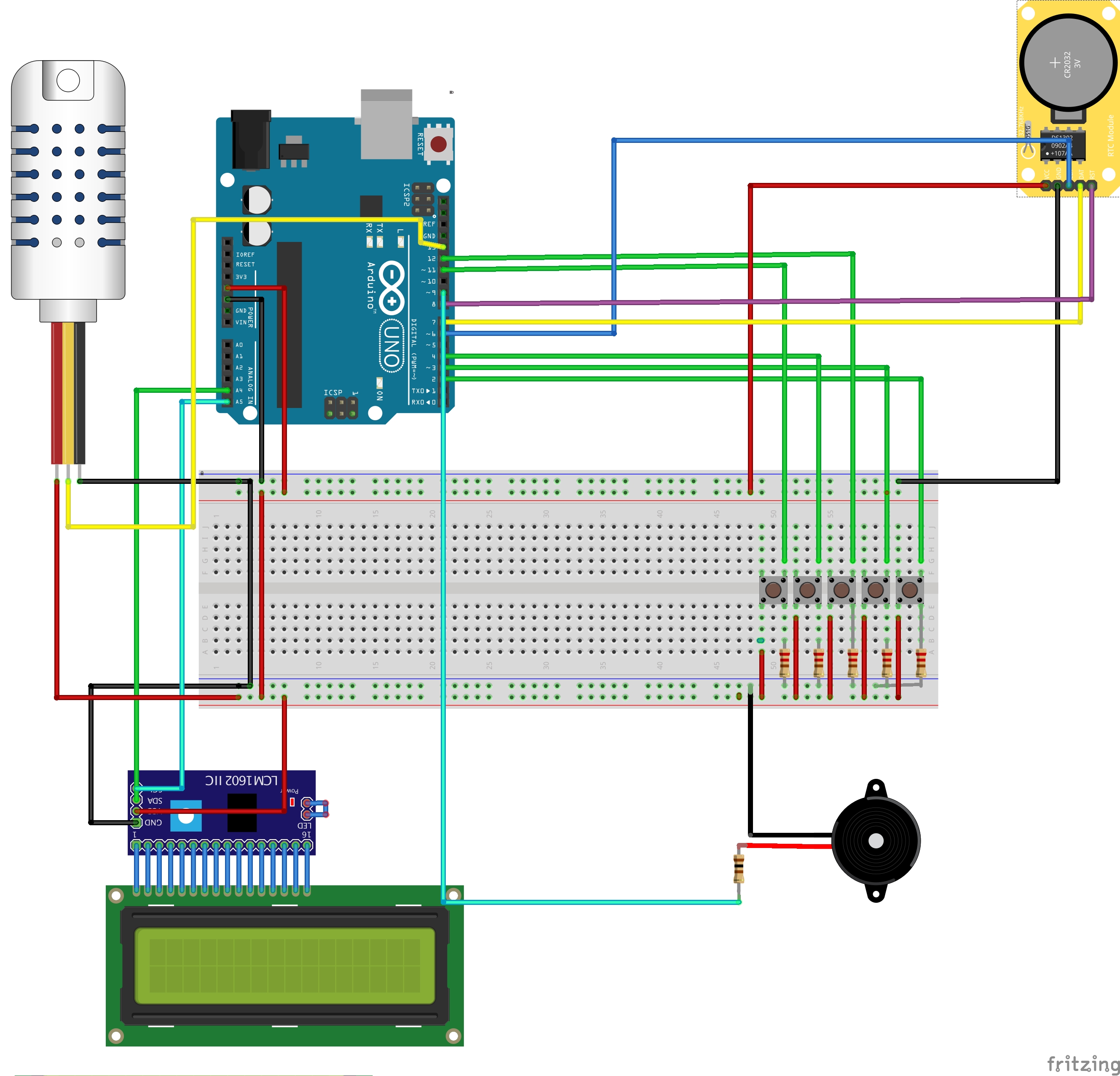
Button #1 Mode: connected to digital pin 2
Button #2 Select: connected to digital pin 4
Button #3 Plus: connected to digital Pin 3
Button #4 Minus: connected to digital pin 12
Button #5 Timer on/0ff: connected to digital pin 11
You can wire all of the components to a breadboard or wire them to an Arduino proto shield if you would like to use the case.
Libraries:
DHT - https://github.com/adafruit/DHT-sensor-library
LiquidCrystal I2C - https://www.arduinolibraries.info/libraries/liquid-crystal-i2-c
Wire - https://github.com/arduino/ArduinoCore-avr/tree/master/libraries/Wire
virtuabotixRTC - https://github.com/chrisfryer78/ArduinoRTClibrary
RTCLib - https://github.com/adafruit/RTClib
Usage:
- Change between screens by pressing the mode button.
- Set time by holding the mode button on screen 1.
- Screen 1: Time, date, and temperature
- Screen 2: Set up the alarm.
- Screen 3: timer
- Screen 4: Alarm On/Off
To navigate between all of the screen we will use the mode button.
Each button has its own use the + and - buttons are most used to add to a number or decrse, The selecet button is sually to go between couple of options and the timer button is to start or stop the timer.
Expanded Technical Details
The All-in-One Clock 1.0 aggregates multiple sensors into a single, unified dashboard. By syncing a precise Real-Time Clock (RTC) with environmental sensors, the Arduino serves as a central data aggregator, formatting and displaying the information on an LCD.
Structuring the Sensor Ecosystem
Managing multiple sensors efficiently requires careful planning of the communication buses:
- I2C Bus Sharing: Modules like the DS3231 RTC and BMP280 barometric pressure sensor can share the same I2C bus (SDA/SCL pins). The Arduino communicates with each independently using their unique device addresses.
- Digital Pin for DHT: The DHT22 temperature and humidity sensor uses a single digital pin for its proprietary one-wire communication protocol.
- SPI for Display: A TFT display, as shown in the wiring diagram above, typically requires the high-speed Hardware SPI bus (MOSI, MISO, SCK pins) for efficient data transfer.
A core programming challenge is updating the display without causing a distracting flicker. The naive method of clearing the entire screen (tft.fillScreen(BLACK)) on every loop cycle causes a flash. The professional approach is dynamic redrawing:
- Draw all static text (like labels "TEMP:" or "TIME:") once during setup.
- In the main loop, before updating a changing value (like the temperature number), use
tft.fillRect()to draw a black box only over the area where that number appears. - Write the new value in that same spot. This method updates only the pixels that have changed, resulting in a smooth, flicker-free display.
Integrated Telemetry Hardware Base
A robust build for an expanded version of this project could include:
- Arduino Mega 2560: Provides ample memory for handling graphics libraries and multiple sensors.
- ILI9341 SPI TFT Color LCD Screen: For a high-definition graphical display.
- DS3231 I2C RTC Module: For maintaining accurate time.
- DHT22 Temperature & Humidity Sensor.
- BMP280 I2C Barometric Pressure Sensor: To add atmospheric pressure and altitude data.
Version 2.0
For version 2.o follow this link: All In One Clock 2.0