Please visit https://proteshea.com/analog-input-channels-with-arduino-uno/ for a complete list of materials needed for this project.
Introduction
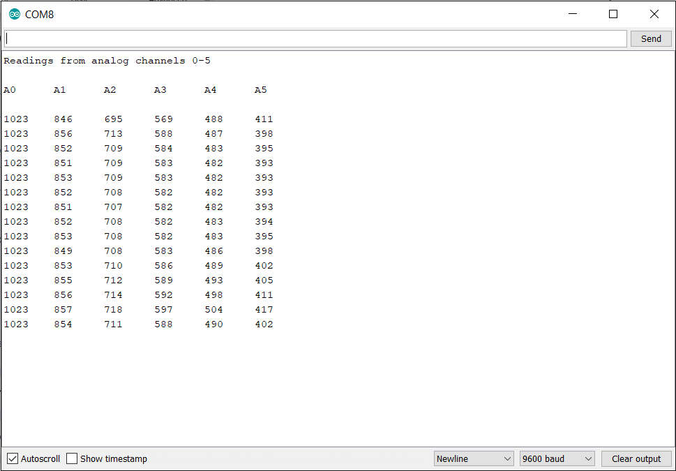
If you followed along with our previous projects, you should have a good understanding of how to use the digital I/O for control, communication, and reading inputs on the Arduino Uno Rev3 (Uno). In this project, we’re going to show you how to use the analog input channels. The number of channels varies per board, but the Uno has six channels. You will learn how to read each channel and display the value into an organized table on the Serial Monitor, as shown below.
In the real world, most signals aren't just "on" or "off" (0 or 1); they are continuous signals, such as temperature, light intensity, or constantly changing voltage. We will delve into the use of Analog Input Channels, which are crucial for connecting Arduino to analog sensors. The Arduino Uno board comes with a total of 6 analog channels (A0-A5). We will learn how to read values from each channel simultaneously and organize the data for professional tabular display on the Serial Monitor.
Potentiometer
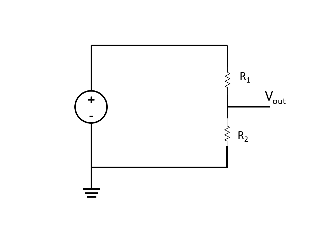
The potentiometer is a component that consists of 3 pins and allows you to quickly vary the internal resistance. By varying the resistance, the output voltage is changed between 0V and the maximum voltage that the potentiometer is tied to. For example, if pin 1 is tied to +5Vdc and pin 3 is tied to 0V (GND), the output voltage on pin 2 will vary between 0V and +5V. The potentiometer acts as a voltage divider circuit, as shown below.
Commonly referred to as a "variable resistor," it is a 3-pin device that functions as a Voltage Divider. Internally, it consists of a resistive track and a movable wiper. As we rotate its shaft, the resistance between pin 2 (the center pin) and pins 1 and 3 changes. In engineering, if we connect pin 1 to 0V (GND) and pin 3 to +5Vdc, the voltage output from pin 2 (Wiper) will change linearly with the rotational position, ranging from 0V to 5V. This is the fundamental circuit known as a Voltage Divider Circuit.
Analog Input
On each analog input channel, there is a 10-bit analog-to-digital (ADC) converter. Being that it has a 10-bit resolution, we can acquire samples ranging from 0 to 1023 (2^10 – 1). If your voltage range is from 0-5V, 0V will be mapped to 0 and 5V will be mapped to 1023. To figure out what each voltage between 0V and 5V will get mapped to, we can use the ratio below.
Each Analog Input channel of the Arduino Uno has a built-in 10-bit Analog-to-Digital Converter (ADC) circuit. The ATmega328P microcontroller chip converts analog voltage into digital numbers that the computer can understand. With a 10-bit resolution, the resulting values will have a total of $2^{10}$ levels, or values ranging from 0 to 1023.
- If the input voltage is 0V, the ADC value read will be 0.
- If the input voltage is 5V, the ADC value read will be 1023.
We can calculate the relationship between voltage and digital values using the equation in the image below.

Let’s say we acquire a voltage sample of 1V. We know n, the max input voltage, and the voltage sample, so we can solve for the ADC value, as shown below. Since the solution is not a whole number, the ADC will round down to the nearest whole number which is 204.
Calculation Example: Suppose we measure a voltage of 1V, with a reference voltage (Vref) of 5V. The calculated ADC value will be: $(1V / 5V) \times 1023 = 204.6$ Since the ADC operates with integer values, the system will round down the decimal fraction, making the actual read value 204.

Wiring the Circuit
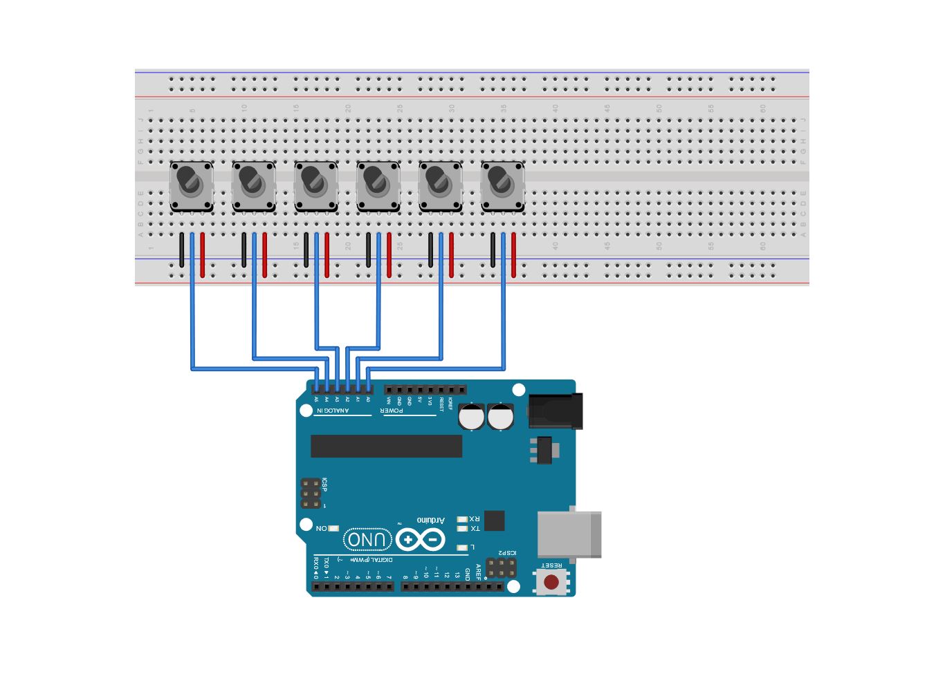
Place six 10kΩ potentiometers onto the breadboard. Wire pin 3 of each potentiometer to the positive voltage rail and pin 1 to the negative rail of the breadboard. Insert a male jumper into each node that pin 2 of the potentiometers are connected to. Then, wire the other end of each jumper to Analog Inputs 0-5. A circuit schematic is shown below.
In this project, we will use six 10kΩ potentiometers to test simultaneous reading from all channels:
- Insert all six potentiometers onto the breadboard.
- Connect pin 3 of each potentiometer to the positive power rail (+5V).
- Connect pin 1 of each potentiometer to the ground rail (GND).
- Use jumper wires to connect pin 2 (Wiper) of each potentiometer to Analog Input ports A0, A1, A2, A3, A4, and A5, respectively.
FuelCan Wiring
If you haven’t mounted the Uno onto the prototyping area of the FuelCan, go ahead and do that. I placed the breadboard in the bottom storage compartment to limit the length of the jumper wires. We need to supply +5V and GND to the power and ground rails on the breadboard. Use the provided banana jack to test-lead clip cables to do so. You will need two male header pins to mount the test-lead clips on the breadboard side. Plug the Type A side of the USB cable into USB1 receptacle and the Type B side into the Uno’s receptacle. Power up the FuelCan with the AC-DC power adapter.
If you are using the FuelCan learning kit, install the Uno board into the Prototyping Area. It is recommended to place the breadboard in the lower storage compartment to save space and manage wires more easily.
- Use Banana Jack to Test-lead clips to supply +5V and GND from the FuelCan's power supply to the breadboard's power rails.
- Connect a USB Type A cable to the computer and a Type B cable to the Arduino Uno.
- Turn on the FuelCan switch to begin powering the circuit.
Software
Once the wiring is complete and the FuelCan is powered up, we can now load the sketch onto the Uno. The sketch is below. It sets up the serial terminal between the Uno and the host. The analog values are read from each analog input and the values are sent to the host to display them on the Serial Monitor. Rotate each potentiometer clockwise and counterclockwise to watch the values change from 0 to 1023.
This source code is designed to leverage the analogRead() command's efficiency and manage output via the Serial Monitor. The program's logic is divided into key sections as follows:
- Setup: Initializes Serial communication at a specified Baud rate, preparing to send data back to the computer.
- Loop:
- The program uses the
analogRead(pin)function to read voltage values from pins A0 to A5. - The obtained data is stored in variables and output via
Serial.print(). - Control characters like Tab (
\t) are used to align numbers into columns, making it easy to observe changes across all 6 channels.
- The program uses the
Testing Instructions: Once the code has been uploaded, open the Serial Monitor. Then, try rotating each potentiometer clockwise and counter-clockwise. You will see the values in the table fluctuate between 0 and 1023 in real-time. This change demonstrates the ADC's precision in detecting even small voltage differences (approximately 4.88 millivolts per digital unit).
// Basic source code example for reading 6 channels
void setup() {
  Serial.begin(9600);
  Serial.println("A0\tA1\tA2\tA3\tA4\tA5"); // Table header
}

void loop() {
  for (int i = 0; i < 6; i++) {
    Serial.print(analogRead(i)); // Read values from pins A0 - A5
    Serial.print("\t");          // Separate with Tab
  }
  Serial.println();              // New line
  delay(100);                    // Delay to stabilize readings
}
With this foundation, you can apply it to read values from real sensors such as LDRs (light measurement), LM35 (temperature measurement), or water level sensors, all of which operate on the principle of analog voltage.