
I was getting ready to join a small team of folks in conducting a Maker Experience for a group of High School students in Oakland, CA. Maker can mean a lot of things – for us it meant a focus on thinking about real world problems that can be simulated or solved via the Arduino with sensors and actuators. We had chosen the Arduino 101 along with the Grove Starter Kit for Arduino as our platform and were looking for a capstone project that would reinforce lots of the concepts we had been teaching as well as being memorable and fun. Through my network, I found some awesome Rover kits that were based on Edison and used Wi-Fi - it was the Seeedstudio Skeleton Bot - a 4WD mobile robotic platform. This platform has been around for a few years, but they were really high performance and very cool, so I decided to try to convert the Rover kits to use Arduino 101 and Bluetooth Low Energy communication. We had a great project for our Maker Experience! This tutorial describes the build/conversion of that Edison based 4WD kit to use Arduino 101.
There are quite a few Arduino based rovers on the internet - so what do I hope to add with this tutorial?
1. A practical example using the Arduino 101. With built-in wireless Bluetooth Low Energy communications (BLE) and a 6-axis Inertial Measurement Unit (IMU) - it feels like the Arduino 101 is made for motion! However, I could not find many real projects that put these new capabilities to use. This tutorial utilizes both the Arduino 101 BLE and IMU features in a useful way.
2. I also highlight the use of the Grove Starter Kit for Arduino, since it allows me to quickly add sensors and actuators (from a large catalog of inexpensive sensors) without the need to breadboard, which is more difficult and time consuming for me. This is a personal preference and not intended as a "knock" on those who are skilled at breadboarding.
3. My Arduino code is very modular - so hopefully it is usable even if you don't use the same motors, motor controller or the grove kit.
All software and schematics are provided. First, I describe building a basic 4WD Rover - Arduino based motor control taking commands via BLE from a smartphone - Android or IOS. In testing, I crashed the Rover a few times and found that trying to pick it up after I "turtled" it, with its knobby tires spinning fast, wasn't very safe. I decided to add a routine to detect crashes and turn the motors off when I crashed. I also have a few ideas for improving the rover and I will outline some of those at the end.
During the build, I benefited so much from public sample code and tips, I wanted to share what I learned in the hope that others can benefit from my work.
The high level steps for this tutorial are as follows:
1. Assemble the Rover “Rolling Chassis”
2. Electrical Assembly
3. Testing motor control with the Arduino 101
4. Building the BLE Remote Control – covered in a separate Instructable
5. Programming the Arduino 101 for a “Base Model” Rover
6. Adding a “Crash Detect” safety option
7. Final Thoughts and Future Enhancements
Detailed Hardware Bill of Materials:
1. Arduino 101 board
2. Grove Starter Kit for Arduino
- Grove Base Shield v2.0
- Grove I2C RGB LCD Backlight Display v2.0
- Grove Button
- Grove LED Socket v1.3 with Blue LED
- Grove Cables (4 ea.)
3. Skeleton Bot – 4WD Mobile Robotic Platform
- Aluminum chassis and drilled acrylic plates - part of
- 25GA-370 DC motor (4 ea.) with wires for + and -
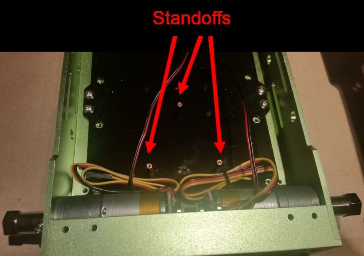
- Grove I2C Motor Driver Board with 3 ea. 0.25” standoffs, screws
- 85mm Wheels, axels, screws (4 ea.)
- 1” Aluminum standoffs, screws for mounting Arduino
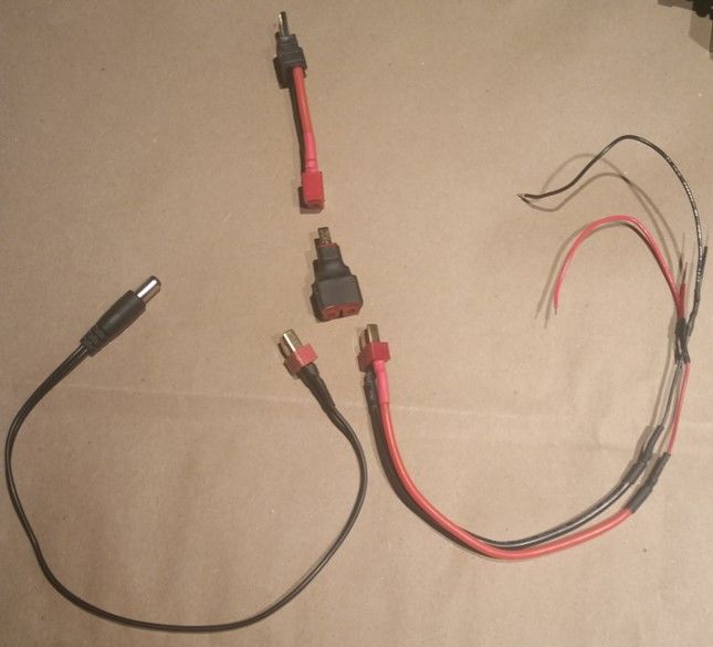
- Dean’s male pigtail for connecting to motor driver
- Dean’s “T” – 2 female connectors tied to one male connector
- Dean’s male with Arduino barrel jack
- Dean’s female to Traxxas connector
- Traxxas Li-Po 30C 5000mAh 2S 7.4V Battery
Step 1: Assemble the Rover “Rolling Chassis”
To create a “Rolling Chassis” from the Skeleton Bot – 4WD Mobile Robotic Platform – it is best to follow the recipe at Seeedstudio.com. I received the rover kit with the main body pre-assembled. This step can be completed by following the detailed instructions located at: http://www.seeedstudio.com/recipe/index.php?m=Hom...
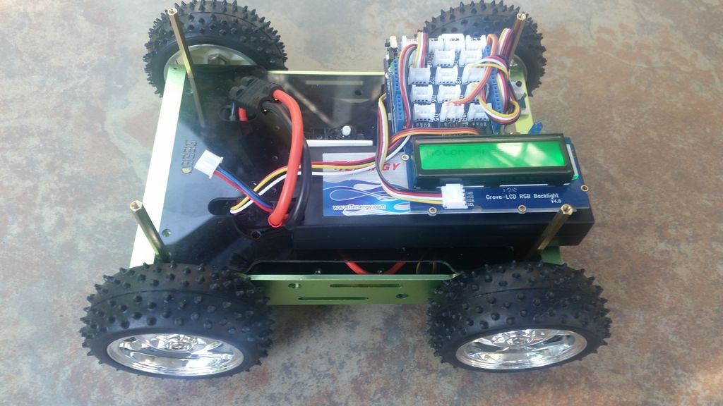
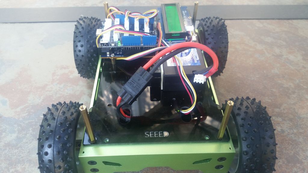
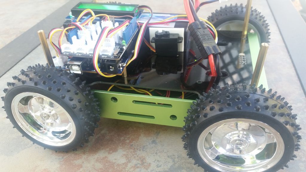
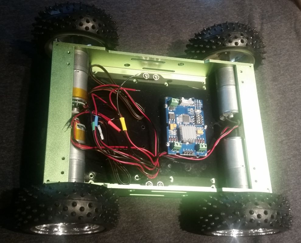
I have included several pictures of the Rover kit at the completion of this step. Mounting the wheels at this step versus later is a matter of preference. I feel it is easier to test with the wheels off. But with the wheels on, the rover can sit on a block or box – allowing the wheels to spin freely - this works just as well.
Step 2: Electrical Assembly:
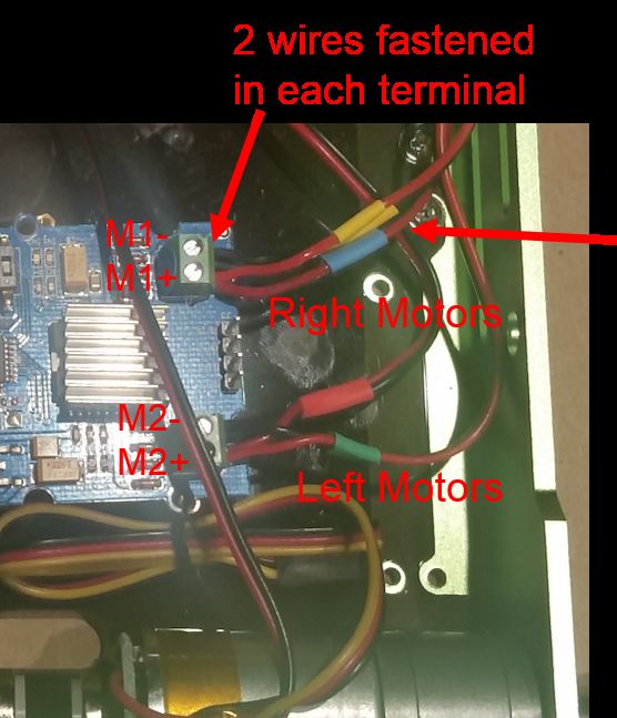
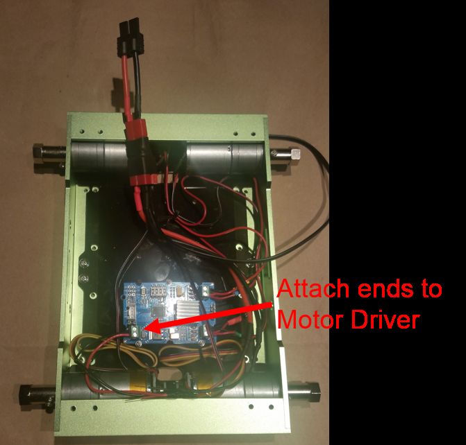
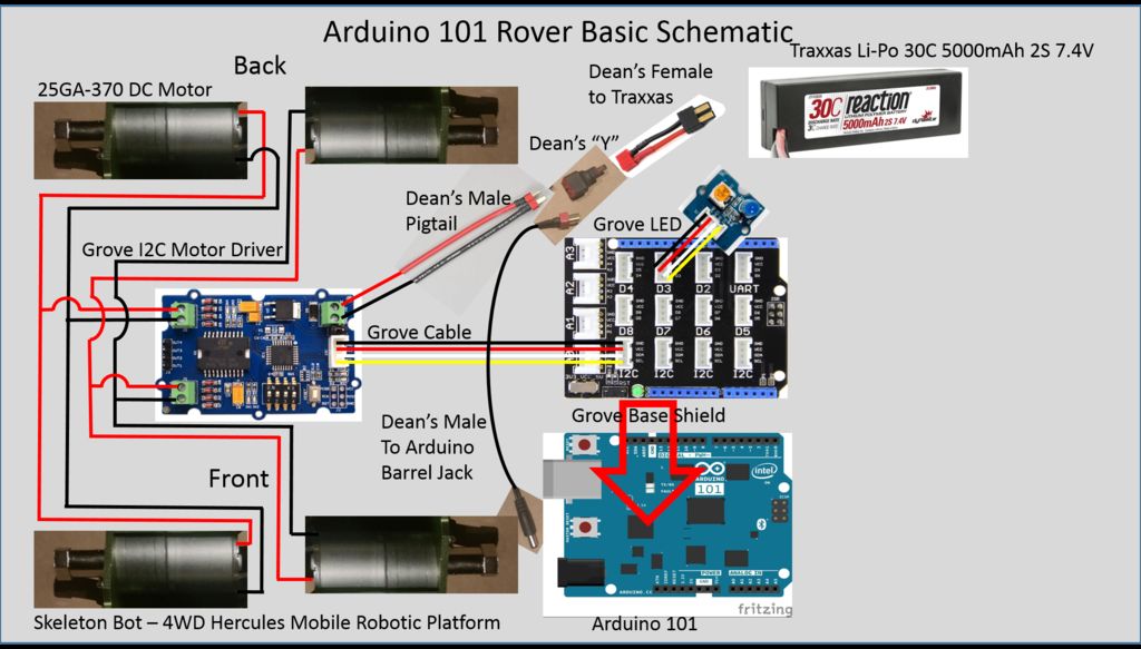
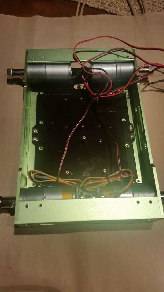
My DC motors came with wires already attached as can be observed in the previous step. I attached the wires from the left motors to Motor Driver 1 and from the right motors to Motor Driver 2 as can be seen in the schematic and photo. Securing the two sets of wires in the small screw-down connectors was challenging.
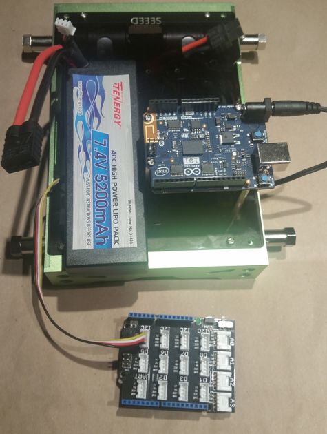
I assembled the power cable next. The different pieces of the power cable came with the kit and provide an ingenious way of connecting an RC car battery to the rover. I assembled it as shown.
As mentioned, the Lithium Polymer battery being used is a typical Radio Controlled car battery. It is a 2S battery – meaning is puts two of the 18650 battery elements in series. 18650s are rated at 3.7 volts, so having two in series, yields a 7.4 volt input for the motor driver.
In terms of output, the Grove I2C motor driver integrates an L298P dual H-bridge capable of delivering 2A per motor driver. It is also capable of driving DC motors in both directions and controlling speed and direction of each of the motor drivers independently. One additional feature of the Grove I2C Motor Driver board is that it has an onboard 5V regulator which can be used to power the Arduino through the I2C bus. I experimented and found that this worked well - the Arduino did not need to be powered by the barrel jack (or USB cable) when the battery was attached to the motor driver board. For more information on the this motor driver, please see the wiki entry at: http://www.seeedstudio.com/wiki/Grove_-_I2C_Motor_Driver_V1.3
I made sure to attach a grove cable and to feed the battery connector through a slot in the top acrylic plate before screwing it in place.
Step 3: Testing Motor Control
In order to ensure that the wiring was done correctly, I needed some simple Arduino code to spin the 4 motors at different speeds and different directions. The left motor in the front and the left motor in the back should spin identically. The same is true of the pair of motors on the right.
I found a good piece of code at: http://www.seeedstudio.com/wiki/images/8/8c/I2CMo...
I made a couple of modifications to adjust the speed of the motors in the loop. The code I used to test is attached.
Ensure that each motor turns, at three different speeds and in both directions. If that is not what you observe, check the wiring and retest until correct. I have attached a short video showing a successful motor test.
Step 4: Building the BLE Remote Control
Building the Arduino 101 BLE Rover Remote Control is covered in a different tutorial here.
Step 5: Programming the Arduino 101 for a “Base Model” Rover
I start with a "Base Model" rover code - no frills, minimal options. It must contain:
- Rover control code for translating commands into actions for the motors
- BLE communications code to connect the smartphone to the Arduino.
I structure my code in a traditional way:
- Include libraries and declare global variables
- Setup() function – for code intializing hardware - needed to run once
- Loop() function – for code that runs repeatedly
- User defined functions – for any chunk of code longer than a few lines in the loop
I find that creating user defined functions allows me to keep my code readable and structured – less chance of me writing spaghetti code; that is hard to understand and hard to debug.
The Base model code is a combination of 2 functions for controlling the DC motors – MotorSpeedSetAB and combined with the Rover state machine from deba168’s tutorial: Smartphone Controlled Arduino Rover, which I placed in a user defined function called RoverControl.
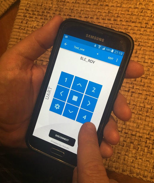
For communication, I modified the CallbackLED sample that showcases the use of Bluetooth LE on the Arduino 101. The main modifications were to define the UART profile (specific BLE characteristics and UUID’s) that the nRF Toolbox application expects to see. This is the application where I defined the remote control on the smartphone. There are several online tutorials on Bluetooth Low Energy (BLE) – I will not go into theoretical depth to explain its inner workings here. Let me walk you through each section of code briefly!
Section 1 (include and declare):
- include the
wire.hlibrary to initialize the I2C bus
- include the
CurieBLE.hlibrary to enable Bluetooth LE communications
- declare variables defining D2 for the Blue LED, state to hold the
RoverControlcommand char,vSpeedSetto hold the char for speed (0-100)
- create a
BLEPeripheralinstance, create aBLEServicefor the UART profile, create a rx and tx characteristics for the service
Section 2 (setup function):
- initialize the I2C bus and serial link
- define D2 as an output – this is the Grove LED pin – blue LED indicating a Bluetooth connection or not
- setup several items related to BLE –
LocalName, add the tx and rx characteristics to the BLE service, define event handlers for connect, disconnect andrxCharacteristicwritten, then start advertising the BLE service
- initialize the DC motors as “off” (both + and – pins low for both motors), DC motor speed set at 50%
Section 3 (loop function):
Here are all 4 lines of code in the loop() function