The idea
I was looking for an easy to read clock for my music room. Having just started experimenting with an Arduino I figured I would build one as my second Arduino project with a 4 in 1 8x8 LED matrix I bought a while ago and to add some additional features.
It displays the day of the week, month, year, time, temperature and humidity. It loops a couple of times and then enters sleep mode: the display turns off and it powers down to save battery power. An interrupt function is called when the PIR sensors detects motion (the LED in the bottom right will flash briefly to indicate it) and the main loop is active again.
The Sketch script can easily be edited to change several settings, like delay times and the numbers of loops, and it can also be expanded with displaying custom texts.
I realize an LED matrix, clock, temperature and motion sensors are pretty standard projects for an Arduino. However, the combination works great for my purposes and in the future I might expand it with Wifi so it can display weather forecasts, news headers, etc as well.
Enormous SPI Cascades: 32x8 LED Matrix
A single 8x8 matrix is simple. Connecting four of them into a massive, uninterrupted 32-column scrolling billboard requires aggressive manipulation of the SPI (Serial Peripheral Interface) hardware clock. The Arduino 32x8 LED Matrix Info Display utilizes the <MD_MAX72xx.h> library to execute cascading byte-shifts across four individual MAX7219 chips, seamlessly rolling massive Strings of text specifically for YouTube subscriber counters or Bitcoin stock tickers!
The Matrix Hardware Configuration (MD_Parola)
Standard libraries completely fail if the generic Chinese hardware blocks are wired differently internally!
- The Architecture Trap: There are 4 different physical PCB designs for these Matrix modules (
FC-16, PAROLA, GENERIC). If you pick the wrong one, the text will be violently mirrored, upside-down, and shifted backwards! - You must define the exact Hardware Type in the incredible MD_Parola engine!
#define HARDWARE_TYPE MD_MAX72XX::FC16_HW // The most common generic red board!
#define MAX_DEVICES 4 // Tell the Uno it has 4 chips to traverse!
#define CS_PIN 10
MD_Parola myDisplay = MD_Parola(HARDWARE_TYPE, CS_PIN, MAX_DEVICES);
The Non-Blocking Text Scrolling Algorithm
You cannot use delay() wrapped around a generic display() function, or the Uno will completely freeze and you can't update the text data from the Internet!
- The
MD_Parolalibrary utilizes aggressive Non-Blocking timing! myDisplay.displayAnimate()is tossed loosely into theloop().- Every millisecond, the C++ code asks: Is it time to shift the pixels left by exactly ONE column?
- If yes, it shifts to
Device 2, Device 3, completely transparent to the programmer! - Data Injection: You can execute
myDisplay.displayText("HELLO WORLD!", PA_CENTER, 100, 1000, PA_SCROLL_LEFT, PA_SCROLL_LEFT);and the massive text block visually slides beautifully from right to left!
Massive Banner Requisites
- Arduino Uno/Nano (Standard functionality).
- A 32x8 (4-In-1) MAX7219 Dot Matrix Display Block (Do not wire four separate 8x8 blocks with loose jumper wires. Buy the single, massive contiguous PCB that has 4 matrices already soldered, otherwise the SPI clock lines will degrade!).
- An external 5V 3-Amp Power Supply (If 256 Red LEDs all shine intensely at the exact same moment, it will violently blow out standard USB ports!).
The setup
Here is my test setup, check the schematic for details:

The code
The project needs 2 standard libraries to work:
- stdio.h
- Wire.h
and 4 additional libraries (the links are in the Code section):
- DS1302.h
- LedControlMS.h
- LowPower.h
- AM2320.h
The LedControlMS.h library displays characters with a width of 5 LEDs per matrix which is 8 LEDs wide. So it leaves 3 LEDs unused. As I didn't like this I wrote an additional function which displays characters 6 LEDs wide at any start column and also across multiple matrices. It can also display multiline texts.
Setting the date and time: set the correct date and time in line 147 (166 for the enhanced version). Uncomment line 86 (99 for the enhanced version) and upload and run the code. Then comment line 86 (or 99) and upload the code again (or else the date and time would be reset to the coded values everytime you power up).
Finished project
The setup built into a photo frame.
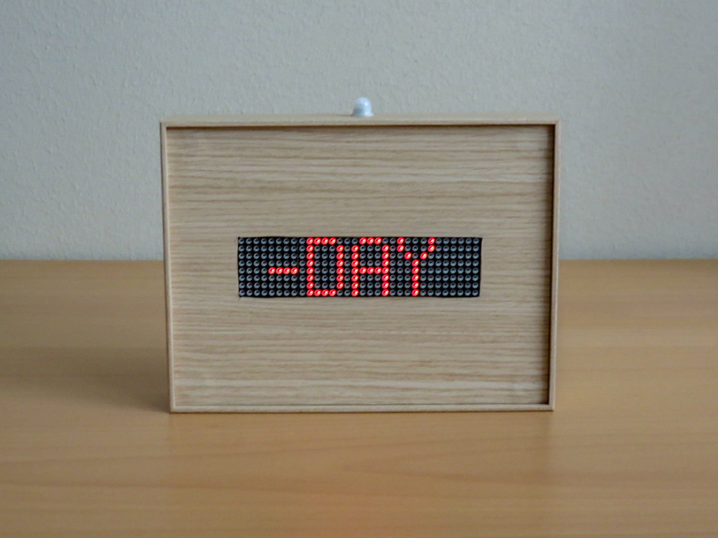
Edit: because of sensitivity issues, I later moved the motion sensor from the top to the frontpanel.
License
Feel free to use the code for your personal use, not for commercial purposes.
You can contact me at ericBcreator@gmail.com.