- My Aim: To create a simple, cheap and open source way to recover data from Amiga DD floppy disks from within Windows 10 and other operating systems.
- My Solution: An Arduino + a Windows application
- Why: To preserve data from these disks for the future. Also, a normal PC can't read Amiga disks due to the way they are written.
Project Website: http://amiga.robsmithdev.co.uk/
This is V1 of the project. V2 contains improved reading and writing!
Amiga Experiences
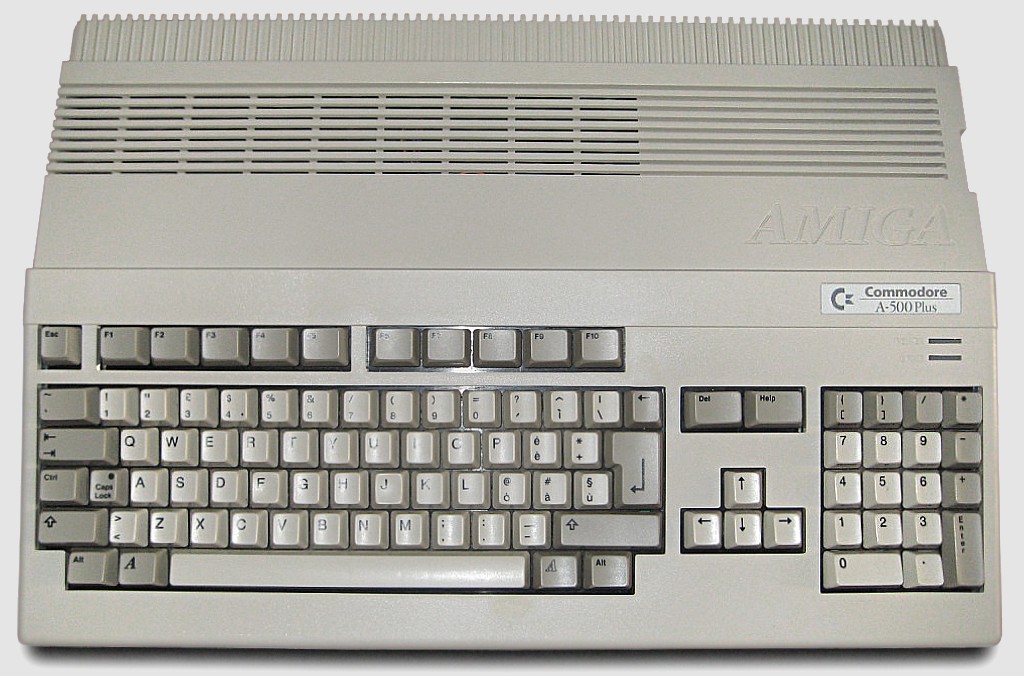
I owe my career to the Amiga, specifically the A500+ that my parents purchased for me for Christmas at the age of 10. At first I played the games, but after a while I started getting curious about what else it could do. I played with the Deluxe Paint III and learnt about Workbench.
The Amiga 500 Plus:
Every month I purchased the popular Amiga Format magazine. One month had a free copy of AMOS. I entered the Amiga Format Write A Game In AMOS competition when AMOS Professional was put on a coverdisk later, and was one of the 12 (I think) winners with In The Pipe Line. You really had to chase them for prizes though!
AMOS - The Creator:

Background
Moving on, I used it as part of my GCSEs and A-Level projects (thanks to Highspeed Pascal, which was compatible with Turbo Pascal on the PC)
Anyway, that was a long time ago, and I have boxes of disks, and an A500+ that doesn’t work anymore, so I thought about backing those disks up onto my computer, for both preservation and nostalgia.
The Amiga Forever website has an excellent list of options that include hardware, and abusing two floppy drives in a PC - Sadly none of these were an option with modern hardware, and the KryoFlux/Catweasel controllers are too expensive. I was really surprised that most of it was closed source.
Massively into electronics and having played with Atmel devices (AT89C4051) whilst at University I decided to take a look at the Arduino (credit to GreatScott for the inspiration showing just how easy it is to get started) I wondered if this was possible.
So I Googled for Arduino floppy drive reading code, and after skipping all of the projects that abused the drive to play music, I didn’t really find any solutions. I found a few discussions in a few groups suggesting it wouldn’t be possible. I did find a project based around an FPGA which was very interesting reading, but not the direction I wanted to go, so the only option was to build a solution myself.
Research
When I started this project I hadn’t got a clue how the floppy drive worked, and even less how the data was encoded onto them. The following websites were invaluable in my understanding on what happens and how they work:
- techtravels.org (and this page)
- The .ADF (Amiga Disk File) format FAQ by Laurent Clévy
- Amiga Forever
- Wikipedia - Amiga Disk File
- English Amiga Board
- QEEWiki - Counters on the ATmega168/328
- Floppy drive pinout
- List of floppy disk formats
Assumptions
Based on the research I now knew theoretically how the data was written to the disk, and how the disk spun.
I began to work out some numbers. Based on the speed the double density disk rotated at (300rpm) and the way the data is stored (80 tracks, 11 sectors per track and 512 bytes per sector, encoded using MFM), to read the data accurately I needed to be able to sample the data at 500Khz; that’s quite fast when you consider the Arduino is only running at 16Mhz.
In the attempts that follow I’m only talking about the Arduino side. Jump to decoding.
Attempt 1:
First I needed to gather the hardware and interface to the floppy drive. The floppy drive I took from an old PC at work, and grabbed its IDE cable at the same time.
Below is a photo of liberated floppy drive from an old PC:
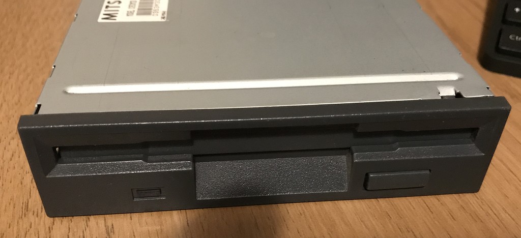
Studying the pinout of the drive I realised I only needed a few of the wires from it, and after looking at the drive I realised it didn't use the 12v input either.
Getting the drive spinning was achieved by selecting the drive and enabling the motor. Moving the head was simple. You set the /DIR pin high or low, and then pulsed the /STEP pin. You could tell if the head had reached track 0 (the first track) by monitoring the /TRK00 pin.
I was curious about the /INDEX pin. This pulses once each rotation. As the Amiga doesn't use this to find the start of the track I didn't need it and could ignore it. After this its just a matter of choosing which side of the disk to read (/SIDE1) and connecting up /RDATA.
With the high data rate requirement my first thought was to find a way to make this less of an issue by trying to reduce the requirements on this rate.
The plan was to use two 8-bit shift registers (SN74HC594N) to reduce the required sampling frequency by a factor of 8. I used was what Ebay called Pro Mini atmega328 Board 5V 16M Arduino Compatible Nano (so I dont know what that is officially, but this does work on the Uno!) to buffer this parallel data and send it to the PC using it’s serial/USART interface. I knew this needed to be running faster than 500Kbaud (with all of the serial overhead involved too).
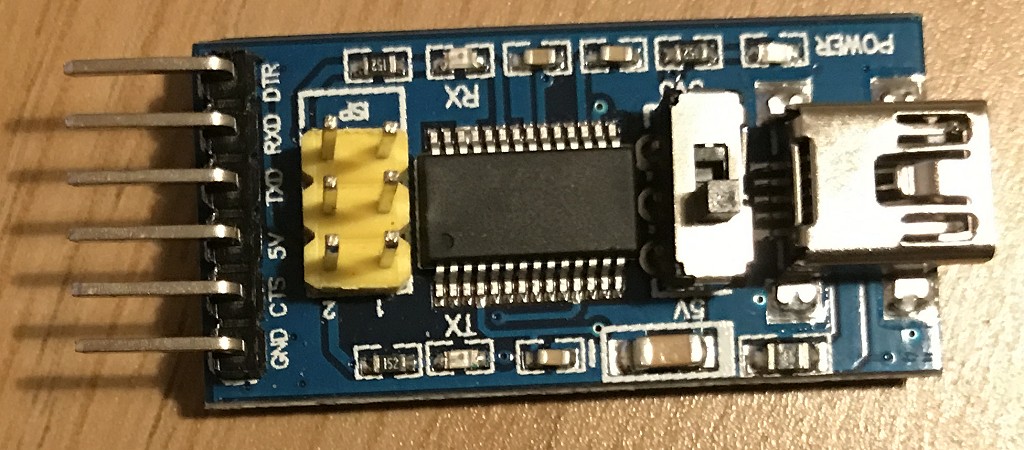
After ditching the standard Arduino serial library, I was really pleased to find I could configure the USART on the Arduino at uptp 2M baud, and with one of those F2DI break-out boards (eBay called it Basic Breakout Board For FTDI FT232RL USB to Serial IC For Arduino - see below) I could happily and send and receive data at this rate (62.5Khz) but I needed to do this accurately.
The FTDI breakout board that perfectly fits the interface on the Arduino board:
First, I used the Arduino to setup on of the 8-bit shift registers only one of the 8 bits clocked high. The other received a feed directly from the floppy drive (thus providing serial to parallel conversion).
The following is a crazy picture of the breadboard I built this on at the time:
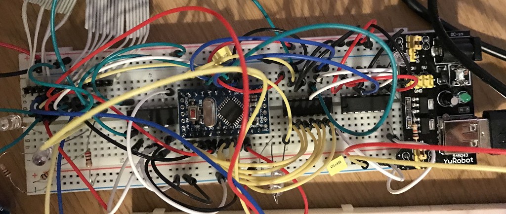
I used one of the Arduinos timers to generate a 500Khz signal on one of its output pins and as the hardware manages this it is very accurate! - Well, my multimeter measured it as exactly 500khz anyway.
The code worked, I clocked in a full 8-bits of data at 62.5khz, leaving the Arduino CPU hardly utilized. However I wasn’t receiving anything meaningful. At this point I realised I needed to take a closer look at the actual data coming out of the floppy drive. So I purchased a cheap old oscilloscope from eBay (Gould OS300 20Mhz Oscilloscope) to check out what was going on.
Whilst waiting for the oscilloscope to arrive I decided to try something else.
A fragment of code used to read the data from the shift registers:
void readTrackData() {
    byte op;

    for (int a=0; a<5632; a++) {
        // We'll wait for the "byte" start marker
        while (digitalRead(PIN_BYTE_READ_SIGNAL)==LOW) {};
        // Read the byte
        op=0;
        if (digitalRead(DATA_LOWER_NIBBLE_PB0)==HIGH) op|=1;
        if (digitalRead(DATA_LOWER_NIBBLE_PB1)==HIGH) op|=2;
        if (digitalRead(DATA_LOWER_NIBBLE_PB2)==HIGH) op|=4;
        if (digitalRead(DATA_LOWER_NIBBLE_PB3)==HIGH) op|=8;
        if (digitalRead(DATA_UPPER_NIBBLE_A0)==HIGH) op|=16;
        if (digitalRead(DATA_UPPER_NIBBLE_A1)==HIGH) op|=32;
        if (digitalRead(DATA_UPPER_NIBBLE_A2)==HIGH) op|=64;
        if (digitalRead(DATA_UPPER_NIBBLE_A3)==HIGH) op|=128;
        writeByteToUART(op);

        // Wait for high to drop again
        while (digitalRead(PIN_BYTE_READ_SIGNAL)==HIGH) {};
    }
}
Attempt 2:
I decided that the shift registers, whilst a nice idea probably weren’t helping. I was able to easily read 8 bits in one go, but it occurred to me that I couldn’t be sure that all of the bits were clocked in correctly in the first place. Reading the documentation it suggested that the data were more of short pulses rather than highs and lows.
I removed the shift registers and wondered what would happen if I tried to check for a pulse from the drive in an Interrupt (ISR) using the previously setup 500Khz signal. I reconfigured the Arduino to generate the ISR, and after I got passed the issues of the Arduino libraries getting in the way (using the ISR I wanted) I moved to Timer 2.
I wrote a short ISR that would shift left a global single byte by one bit and then if the pin connected to the floppy drive data line was LOW (the pulses are low-going) I would OR a 1 onto it. Every 8 times I did this I wrote the completed byte to the USART.
This didn't go as expected! The Arduino started to behave very erratically and strange. I soon realised the ISR was taking more time to execute than than the time between calls to it. I could receive a pulse every 2µSec and based on the speed of the Arduino, and making a wild assumption that every C instruction translated to 1 clock machine code cycle, I realised I could at most have 32 instructions. Sadly most would be more than one instruction, and after Googling I realised the overhead on starting an ISR was massive anyway; not to mention the digitalRead functions being very slow.
I ditched the digitalRead function in favour of accessing the port pins directly! This still didn’t help and wasn’t fast enough. Not prepared to give up, I shelved this approach and decided to move on and try something else.
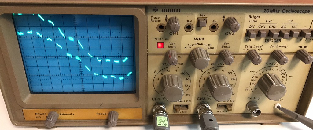
At this point the oscilloscope that I purchased arrived, and it worked! A crusty old Oscilloscope that was probably older than me! But still did the job perfectly. (If you don’t know what an Oscilloscope is check out EEVblog #926 - Introduction To The Oscilloscope, and if you're into electronics then I suggest watching a few more and having a browse around the EEVBlog website.
My newly purchased crusty old Oscilloscope (Gould OS300 20Mhz):
After connecting the 500Khz signal to one channel and the output from the floppy drive to another it was obvious something wasn’t right. The 500Khz signal was a perfect square wave using it as a trigger, the floppy data was all over the place. I could see the pulses, but it was more of a blur.Likewise if I triggered from the floppy drive signal, the 500Khz signal square wave signal was all over the place and not in sync with it.
Photos of the traces on the oscilloscope triggering off of the two channels. You cant quite see it, but on the channel not being triggered is thousands of faint ghostly lines:
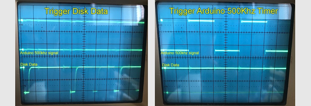
Individually I could measure pulses from both signals at 500Khz, which didn’t make sense, as if they were both running at the same speed but won’t trigger so you can see both signals properly then something must be wrong.
After a lot of playing with the trigger levels I managed to work out what was going on. My signal was a perfect 500Khz, but looking at the floppy drive signal, well they were spaced correctly, but not all the time. Between groups of pulses there was an error drift, ans also gaps in the data that put the signal totally out of sync.
Remembering the previous research, the drive was supposed to rotate at 300rpm, but it might not actually be exactly 300rpm, plus the drive that wrote the data might also not be at exactly 300rpm. Then there is the spacing between sectors and sector gaps. Clearly there was a synchronisation issue, and synchronising the 500Khz signal to the floppy drive at the start of a read wasn’t going to work.
I also discovered that the pulse from the floppy drive was extremely short, although you could modify this by changing the pullup resistor, and if the timing was not exactly right then the Arduino might miss a pulse all together.
When I was at university (University of Leicester) I took a module called embedded system. We studied the Atmel 8051 microcontrollers. One of the projects involved counting pulses from a simulated weather station (rotary encoder). Back then I sampled the pin at regular intervals, but this wasn't very accurate.
The module lecturer, Prof Pont suggested that I should have used the hardware counter features of