When you mix creativity with electronics, it becomes a masterpiece. Producing something original and worthwhile leads to the creation of a number of great new useful household products. In this video, I am going to show you guys how to create this Arduino based touchless concrete clock.
When the art of concrete casting meets embedded systems technology, the result is a masterpiece that blends the raw aesthetics of the material with cutting-edge electronics. This clock not only tells time but also serves as a unique home decoration with an amazing "Touchless" function.
3D Design

I always love to generate a 3D model of my product before creating it in real. This not only gives me a better view of what the final product is going to look like, but also helps me in finding the correct measurements of the final product. So, I went ahead and used the free "Windows 3D-builder" to generate this 3D model.
As an engineer, creating 3D models before actual implementation is a crucial step. It helps us visualize the overall product and verify the precise dimensions of various components. I chose "Windows 3D-builder" for creating this model due to its ease of use and free availability.
The onscreen, black bar is where the TM1637 Digital Clock Module will sit. The gap in the circular concrete frame will house the 5 Blue LEDs that can be turned on or off my moving your hand over the IR Module.
- Central black strip: Designed for mounting the TM1637 digital clock module.
- Circular cutout: For installing 5 blue LEDs to be used as Ambient Light.
These two holes are for the IR Sensor Module. The concrete base bar will house all the remaining electronics components in it.
- Two front holes: Designed to accommodate the IR (Infrared) module's sensors.
- Concrete base: Functions as an enclosure for all circuit boards and electronic components.
The Template

Based on my 3D-Model I designed this 2D-Template. You can download the template from the link provided in the description below and print it on a A4 paper.
To achieve the 3D design, I created a 2D Template to guide the cutting of cardboard for the mold. You can download this Template file from the link below and print it directly onto A4 paper.
Schematic Diagram

Before going ahead, lets have a look at the schematic diagram of the digital clock. The heart of this circuit is an Arduino Nano.
The core of this clock is the Arduino Nano, which processes and controls various modules as follows:
- TM1637 Digital Clock Module: Connects to D4 and D5 pin of the Arduino to display the time.
- DS1302 RTC Module: Connects to the A1, A2 and A3 pin of the Arduino, responsible for keeping accurate time even without power (via a backup battery).
- White LEDs: The two White LEDs displayed on both sides of the digital clock connects to the D11 pin of the Arduino. These two LEDs flash 3 times every hour when the minutes counter is reset to "00".
- IR Module & Blue LEDs: The IR module is connected to the D6 pin of the Arduino and controls the blue cluster of LEDs connected to D12 pin of the Arduino. The infrared sensor detects hand movements. When a hand is swiped past, the system will toggle the blue LEDs on or off.
My initial plan was to have 2 to 3 push button switches connected to D2 and D3 pin of Arduino to set the time of the clock. However in the final version, I did that by adding an extra line of code to my program. I will explain this in full details when we discuss the code.
Preparing The Top - Concrete

Using cardboard I created all the concrete molds. Cardboard was my first choice as it is very easy for me to cut and bend it into any shape of my choice. I used cardboard to create the mold because it's easy to bend and cut. Important steps include pre-drilling holes for ribbon cables and attaching curved internal pieces to create the space for the LEDs.
These holes in the mold you see are for the ribbon cables. Sticking this semi-circular piece on the left side of the inner circle will create the gap for the blue LED cluster when we pore the concrete into the mold.
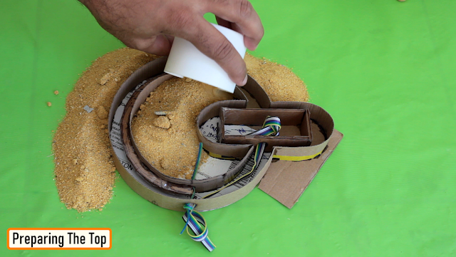
Alright, so this is how it looks like after putting all the pieces of cardboard mold together. Now, lets pour some "Brickies Sand" in-and-around the mold to hold it nice and tight when I pour the liquid concrete. Making the sand a bit wet, will make it firm and will also remove all the unwanted air from the sand.
For casting, I used "Brickies Sand," dampened and packed around the mold to help support its shape and prevent it from shifting while pouring concrete.

Cool, now lets go ahead and pour the concrete into the mold. Don't forget to compress the concrete mixture as you pour it. This way the concrete will reach all the necessary places and will also remove the unwanted air bubble from the mixture.
The technique for smooth concrete pouring involves gentle shaking or tapping to remove air bubbles.

I also added few "Nails" inside the mixture to give it a bit more firmness. This step was absolutely necessary, as my first design completely collapsed because it was not very sturdy. I also embedded "nails" into the concrete to act as reinforcement, helping to make the structure strong and less prone to breakage.
Once the setup dried up I removed all the sand and extracted the piece of art from it.
Preparing The Top - Electronics

Alright, now lets start installing the electronic components to the top section of the clock.
The 4-Digit LED clock module will sit inside this gap. I will cover it up using a black plastic film which I extracted from a wrapping paper. After the concrete has completely dried, we will install the TM1637 display, using a black plastic sheet to cover the screen for a seamless look with the clock body.
For the back, I am using a compressed wood board. Based on my initial design I am going to make some holes in the board and install 3 x push button switches to it. The back is covered with a compressed wood board.
The blue LED cluster will be hot-glued in the gap at the back of the circular section.
I used a plastic cutout from a milk bottle to cover the Blue LED clusters. The white color of the plastic gave it a gloomy look, which was absolutely super awesome. For diffusing the blue LED light, I used translucent white plastic from a milk bottle to create a diffuser, which helps the light emitted have a soft, gloomy look, making it very beautiful.

I hot glues the two white LEDs to the backplate before putting it against the concrete.
Frankly speaking, it was an absolute challenge for me to hot-glue the backplate on the camera. After struggling for a bit, I did that properly behind the scene.
Preparing The Base - Concrete

Now that we are done with the top section, lets start working on the base of the clock.
For the base, I prepared 2 x cardboard boxes with open top one slightly shorter in height than the other. The 2 x straws you see on-screen will create the hole for the IR module. The hole on the side is for the AC power cable. The base was cast to house the Arduino and the IR module. I inserted coffee straws into the mold to create holes for the infrared transmitter and receiver.

The cardboard block I just added is to create a hole on the top of the base, where the circular-top will sit.
Then it was just a matter of pouring the sand inside and outside of the cardboard molds followed by pouring the concrete mixture into it.

Same as before I added some nails to give the structure some additional firmness.
Once the concrete dried up, I extracted the concrete base from the sand and carefully sanded the structure to give it a nice and smooth texture. Once cast and sanded smooth, I installed the control circuit board at the bottom.
Preparing The Base - Electronics

Okie-dokie, now lets install the