Hello everyone,
Today in this instructable we are going to see about arduino based phone. This is phone is a prototype it is still under development. The source code is opensource anyone can modify the code.
Features in phone :1. Music
2. Videos
3. Notes
4.Clock
5. Photos
6. Maps
7. Phone calls
8. Radio
9. Settings
10.Calculator
The program of the project takes less memory. Even you can extend the features of the phone like adding : fingerprint sensor, Messages, GPS........etc.
The core of this phone is arduino mega 2560. The images are stored in sd card from there the images are drawn on screen. You can use sd card 16GB or 32GB.
If you want to edit the code then first see the sample codes and then try to edit the code, because the code is having nearly 2000 lines. So first checkout the sample codes.
Project Perspective
Arduino Based Phone is a sophisticated exploration of telecom technology and mobile interaction. By focusing on the essential building blocks—the touch-UI-to-cellular mapping and your high-performance GSM dispatch and Mega-serial logic—you'll learn how to communicate and synchronize your communication tasks using specialized software logic and a robust high-performance setup.
Technical Implementation: TFT Touches and AT Commands
The project reveals the hidden layers of simple sensing-to-mobile interaction:
- Identification layer: The TFT Touch Screen acts as a high-resolution digital eye, measuring every point of the user's touch to coordinate system dispatch.
- Conversion layer: The system uses a high-speed digital protocol (Serial UART) to receive high-speed AT commands to coordinate mission-critical sensing tasks.
- Audio Interface layer: A Hardware Speaker & Mic provide high-definition voice and numeric feedback for every call status check (e.g., Dialing..., In Call).
- Communication Gateway layer: A SIM800 Module provides a manual network override or automated cellular sync status check during initial calibration to coordinate status.
- Processing Logic: The server code follows a "touch-to-AT-dispatch" (or phone-dispatch) strategy: it interprets TFT coordinates and matches GSM modem states to provide safe and rhythmic mobile calling.
- Communication Dialogue Loop: Status bits are sent rhythmically to the Serial Monitor during initial calibration to coordinate status.
Hardware-Telecom Infrastructure
- Arduino Mega 2560: The "brain" of the project, managing multi-directional UI sampling and coordinating GSM and TFT sync.
- GSM Subsystem: Providing a clear and reliable "Network Link" for every point of global connection.
- TFT Touch Display: Providing a high-capacity and reliable physical interface for your first successful "Phone Mission."
- LiPo Battery: Essential for providing clear and energy-efficient protection for every point of mobile operation.
- Jumper Wires: Essential for providing a clear and energy-efficient digital signal path for all points of your data sensing array.
- Micro-USB Cable: Used to program your Arduino and provides the primary interface for the system controller.
Step 1: Components
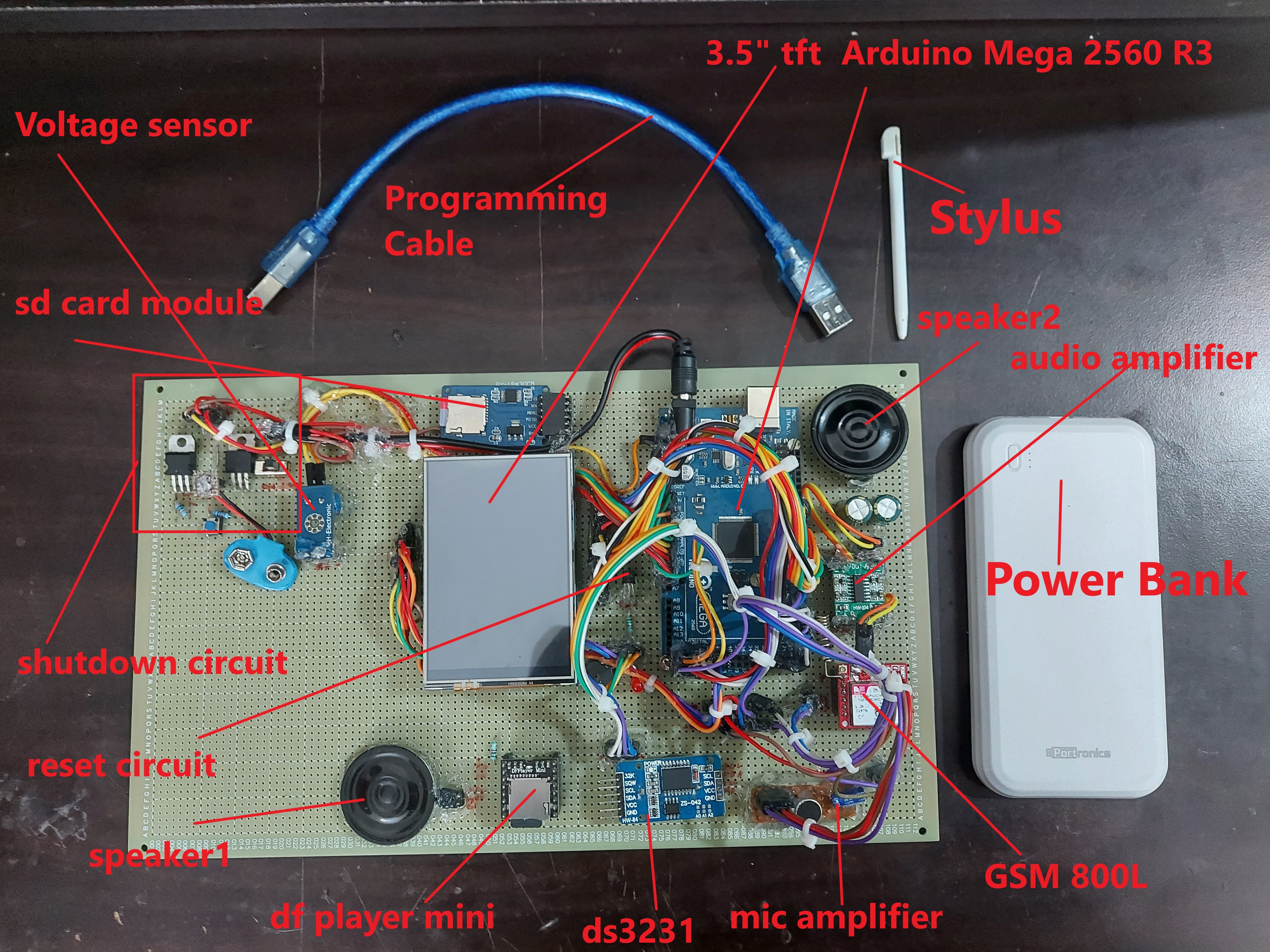
1. Arduino Mega 2560 x1
2. SD card module x1
3. Voltage sensor or current sensor 25v x1
4. 3.5 inch mcu friend tft display x1
5. Df Player Mini x1
6. GSM 800L x1
7. Audio amplifier x1
8. speakers x2
9. 2N3904 NPN transistor x1
10. 1k ohm resistor x2
11. Programmer for arduino x1
12. Mic amplifier x1
13. Male to Female jumper wire x40 (approx.)
14. SD Card 16GB or 32GB x2
15. LED x1
16. Power Bank x1
17. P55NFO6 MOSFET x1
18. IRF9540N MOSFET x1
19. Slide on/off switch x1
20. 300k ohm resistor x1
21. 10k ohm resistor x1
22. Male headers x10 (approx.)
23. Prototyping board 18x30cm x1
24.Tactile push button x1
25. Female headers x10(approx.)
26. Stylus
27. DS3231
Step 2: Hardware Wiring
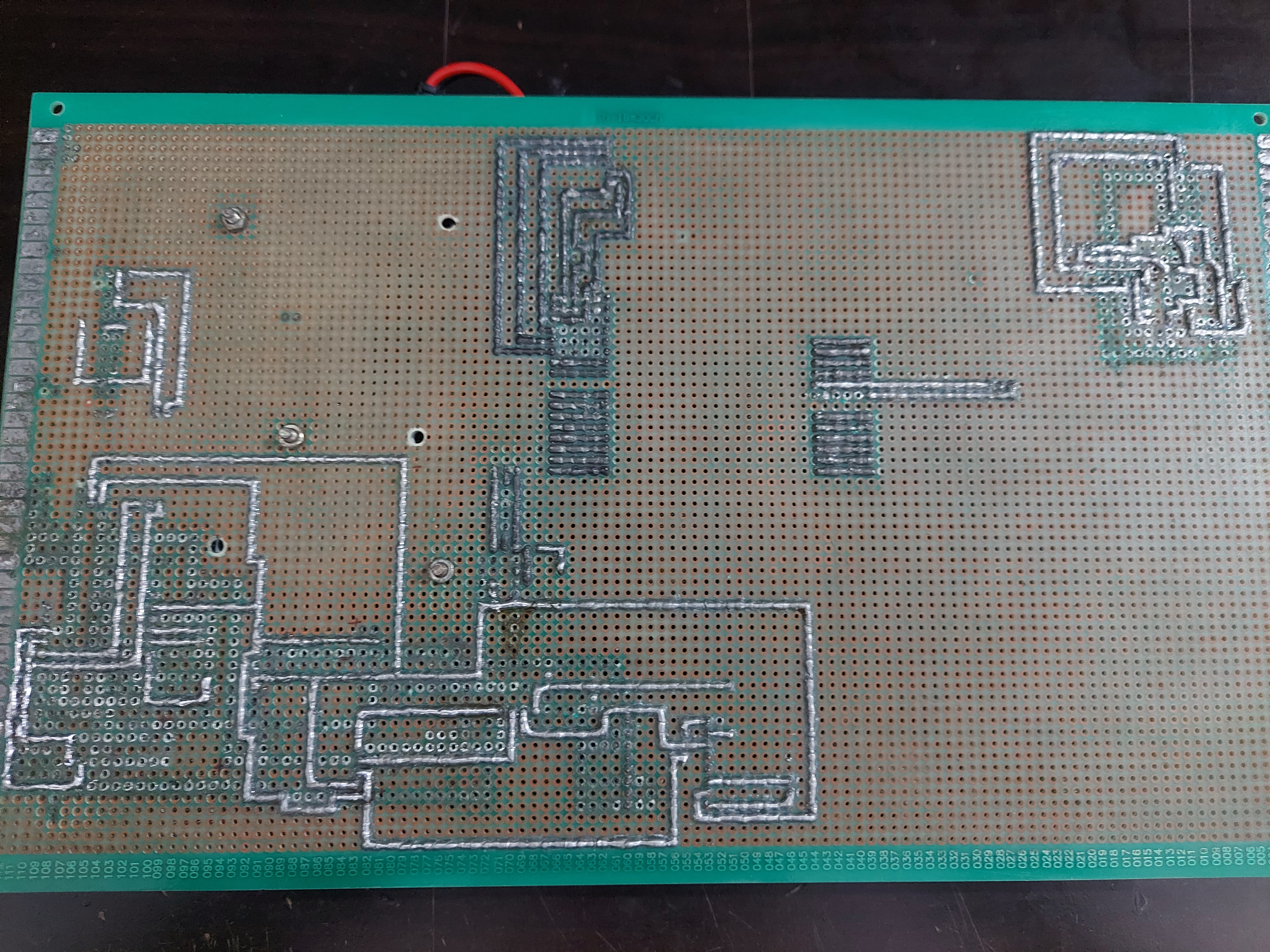
First connect arduino mega 2560 to 3.5 inch mcu tft shield. Next connect sd card module to arduino mega spi pins. Don't forget to insert SD card in sd card breakout module. And also make common 5v and gnd lines. Now connect ds3231 to arduino mega I2C pins. Connect voltage sensor to arduino mega pin A5. Connect led to arduino mega pin 47.
Note: This phone is having one major issue that is current problem this phone consumes a lot of current it needs nearly 2.1 Amps of current. This is due to display it consumes nearly 400ma. If you can control the brightness of the backlight of display then power issue can be solved.SD Card --> Arduino Mega 2560 :
CS -- 53 pin
SCK -- 52 pin
MOSI -- 51 pin
MISO -- 50 pin
VCC -- 5V
GND -- GND
-------------------------------------------------------------------------------------------------------
Arduino Mega 2560 --> Voltage module 25V :
A5 -- output pin of module
GND -- GND of module
JACK +ve -- + of module
JACK-ve -- - of module
-----------------------------------------------------------------------------------------------------
Arduino Mega 2560 --> DS3231 :
SDA -- SDA of Arduino mega
SCL -- SCL of Arduino mega
VCC -- 5V
GND -- GND
-------------------------------------------------------------------------------------------------------
Arduino Mega 2560 --> Df Player Mini :
TX1 of Serial1port -- RX (Note: add a 1k ohm resistor in between TX1 to RX)
RX1 of Serial1port -- TX
GND of Arduino mega -- GND
5V -- VCC
Speaker + -- spk1
Speaker- -- spk2
---------------------------------------------------------------------------------------------------
Arduino Mega 2560 --> LED :
pin 47 -- +ve of led
GND -- -ve of led (place a 1k ohm resistor in between gnd of arduino mega and -ve led)
-----------------------------------------------------------------------------------------------------
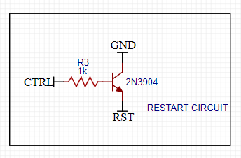
Arduino Mega 2560 --> 2N3904 NPN transistor : (This connection is about resetting the arduino via code)
GND --> Emitter
48 pin --> Base of npn (Note: add an 1k ohm resistor in between 49th pin of arduino and base of the transistor)
RESET --> Collecter
----------------------------------------------------------------------------------------------------
Arduino Mega 2560 --> GSM 800l
TX3 of Serial3port of arduino mega 2560 --> RX of GSM
RX3 of Serial3port of arduino mega 2560 --> TX of GSM
GND --> GND
5V --> VCC
---------------------------------------------------------------------------------------------------
Mic Amplifier --> GSM :
MIC+ --> MIC+ of GSM
MIC- --> MIC- of GSM
GND of mic --> GND of arduino mega
VCC of mic --> 5V of arduino mega
--------------------------------------------------------------------------------------------------
Audio Amplifier --> GSM :
Left --> Spk- of GSM
Right --> Spk+ of GSM
VCC --> 5V of arduino mega
GND --> GND of arduino mega
Spk+ --> Speaker+
Spk- --> Speaker-
-------------------------------------------------------------------------------------------------
ShutDown Circuit :
See in the above pic.
connect ctrl(control pin) to pin 49 of arduino mega
Mobile Hub Automation and Interaction Step-by-Step
The proximity-driven telecom process is designed to be very efficient:
- Initialize Workspace: Correctly seat your GSM and TFT shield inside your custom housing and connect them properly to the Arduino Mega pins.
- Setup High-Speed Sync: In the Arduino sketch, initialize
Serial1.begin(9600)and define the UI buttons insetup(). - Internal Dialogue Loop: The station constantly performs high-performance periodic touch sweeps and updates call status in real-time based on your location and settings.
- Visual and Data Feedback Integration: Watch your smartphone automatically become a rhythmic status signal, pulsing and following your location settings from all points of the grid.
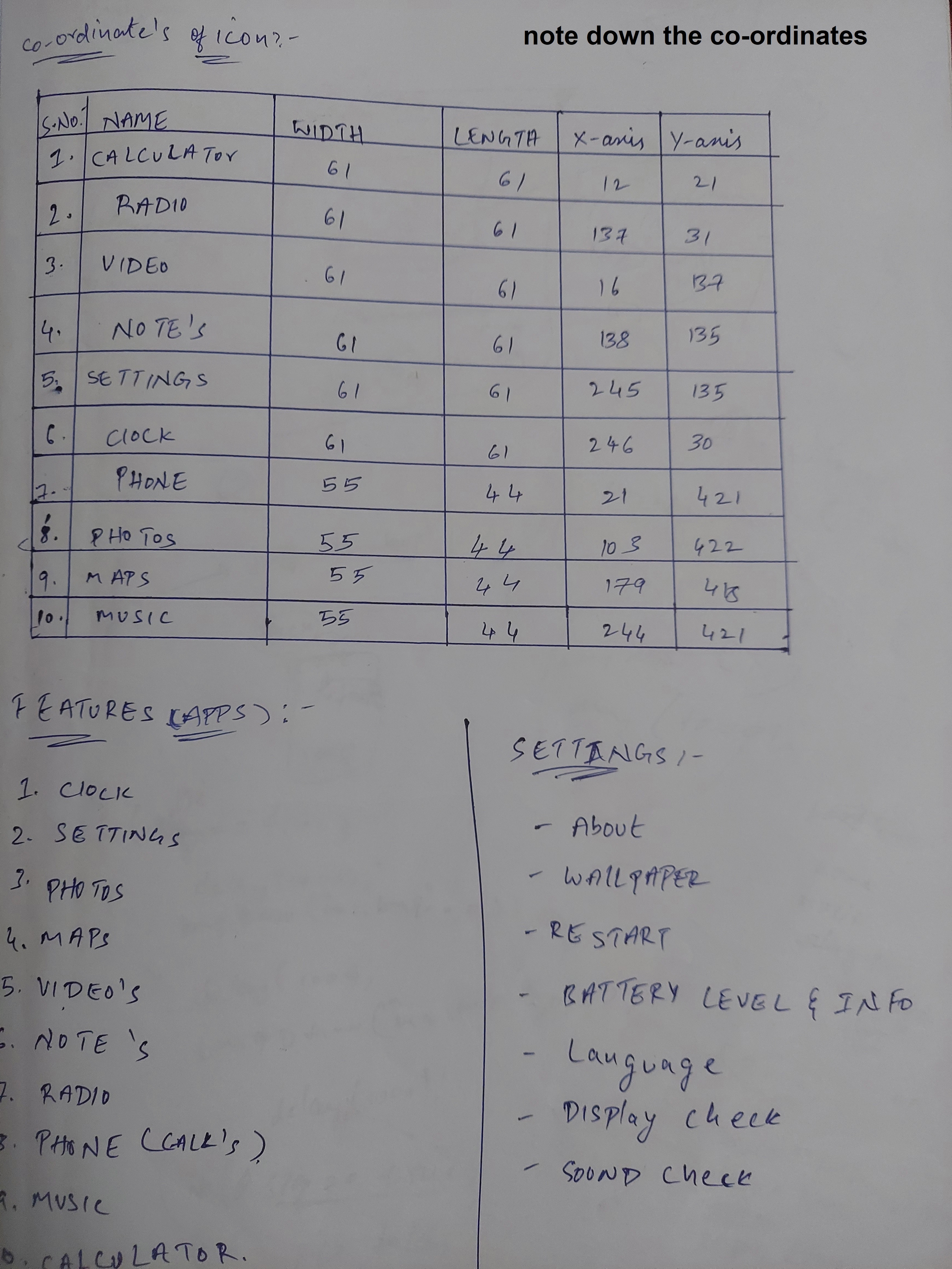
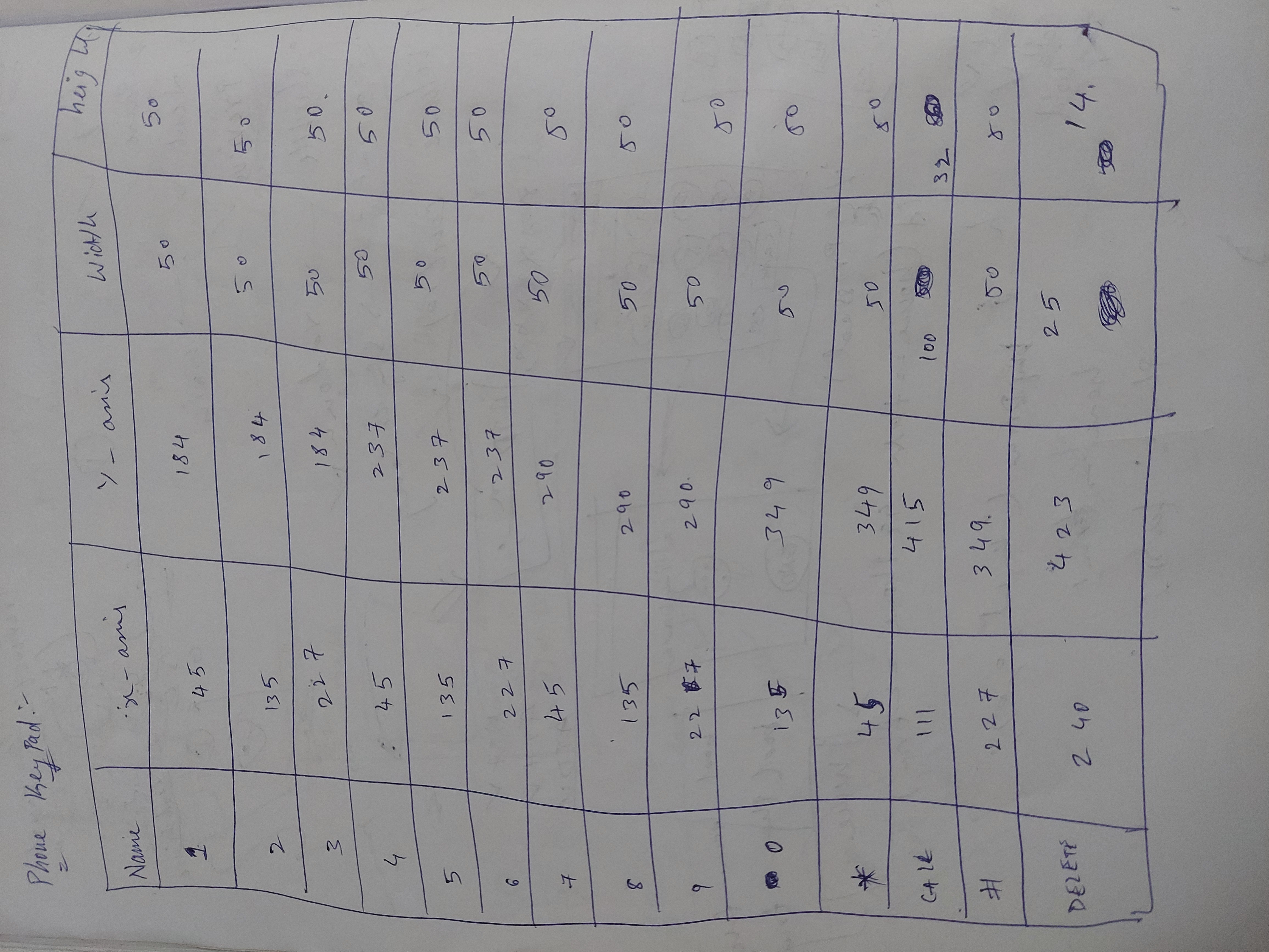
Step 3: How to Find the Co-ordinates of the Icon (If You Want to Add Any Apps Only Then See This )
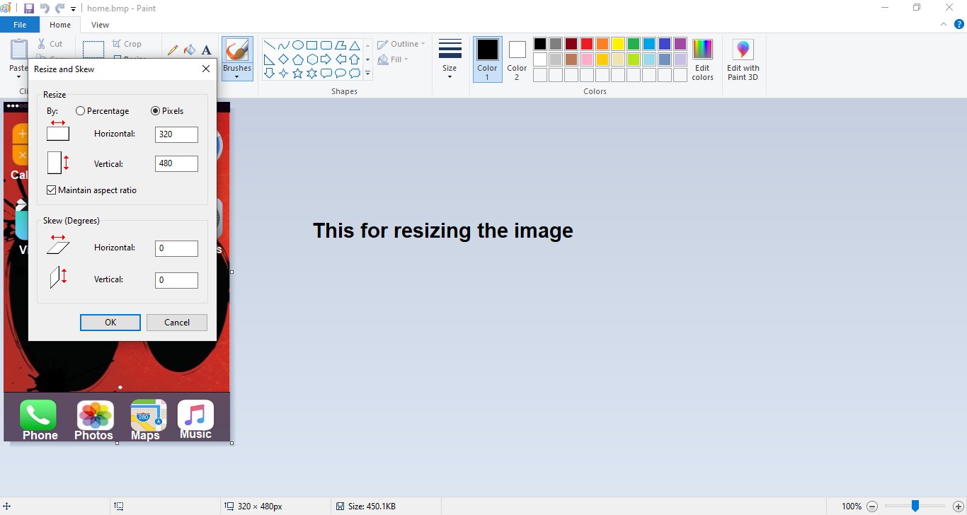
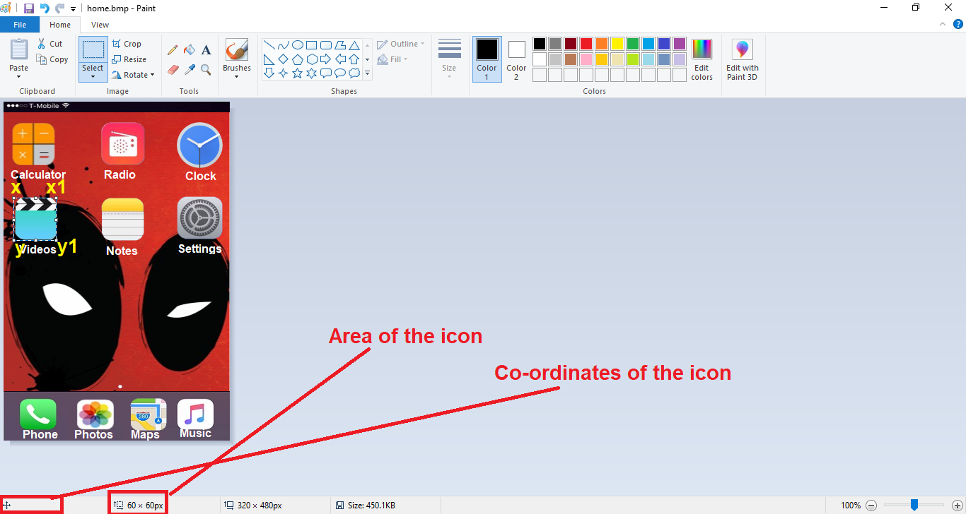
Before this you need to do three things. First the format of the image must be "`.bmp`", Second is name of the image must be equal to 8 letters or less than that, Third thing is the resolution of the image must be 320x480 only.
Now in order to find the co-ordinates of the icons on the screen you need to use windows paint, which is generally free in windows. Now open the paint software and open the image file you want to see the co-ordinates.
Make sure the image size is 320x480 if it's not the use the resize option to resize the image (if you are resizing the image then select the pixels option and type 320 in first box and 480 in second box and click ok.)
Now to find co-ordinates and area of the icon place the mouse on top left corner of the icon now click the left button on mouse and drag the mouse to cover the icon. Now when you see the the bottom of the paint use the area of the icon. To see the co-ordinates of the icon place the mouse on the top left corner now see the bottom left corner of the paint you will see the co-ordinates of the icon don't move the mouse just note down the co-ordinates. This is how you can find the co-ordinates.
If you want to find the x1, y1 co-ordinates also, then first find the length of the icon in horizontally then add this measured length with the x co-ordinate of the icon then the result you get is your x1 co-ordinate do the same thing to find the y1 co-ordinate just here you need to measure the length of the icon vertically an add it with the y co-ordinate of the icon and result you get is y1 co-ordinate.
Step 4: Libraries
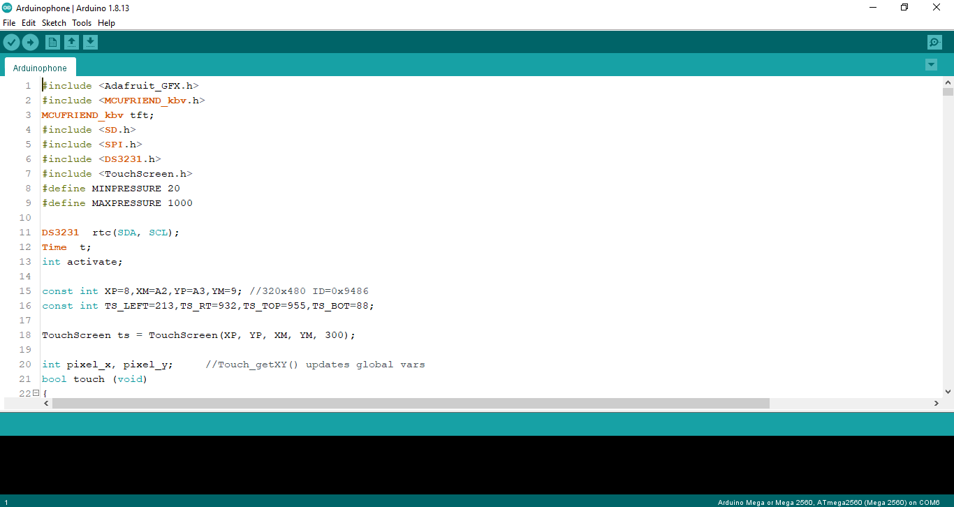
Download the Libraries from below and add to your arduino ide.
1. DS3231 : http://www.rinkydinkelectronics.com/library.php?id...
2. Adafruit_GFX Library : https://github.com/adafruit/Adafruit-GFX-Library.g...
3. MCU Friend Library: https://github.com/prenticedavid/MCUFRIEND_kbv.git
4. Adafruit_TouchScreen Libary: https://github.com/adafruit/Adafruit_TouchScreen.g...
Download this libraries only there is no need to download DF player mini library, SD card library and SPI library.
SPI and SD card library are already preinstalled in Arduino IDE and DF player mini program is written in the code.
Step 5: How to Set Date and Time
Before this make sure that DS3231 library is installed in Arduino ide.
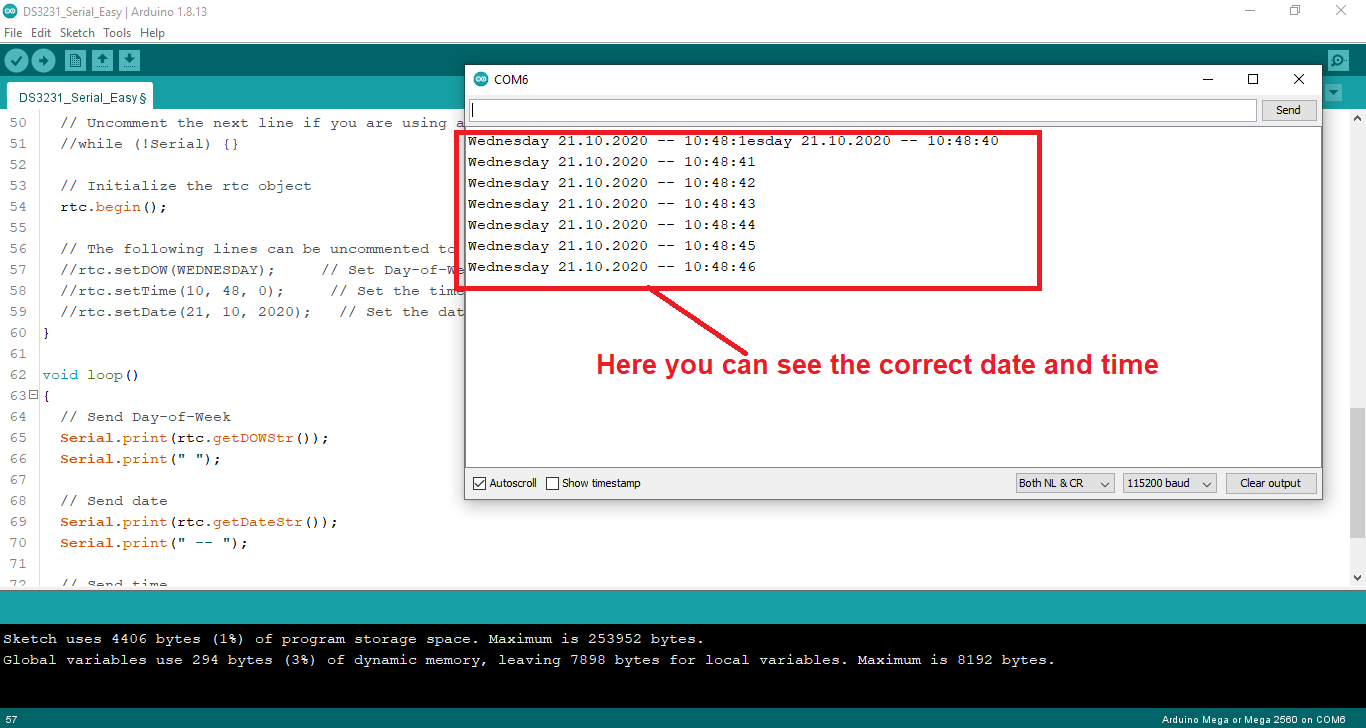
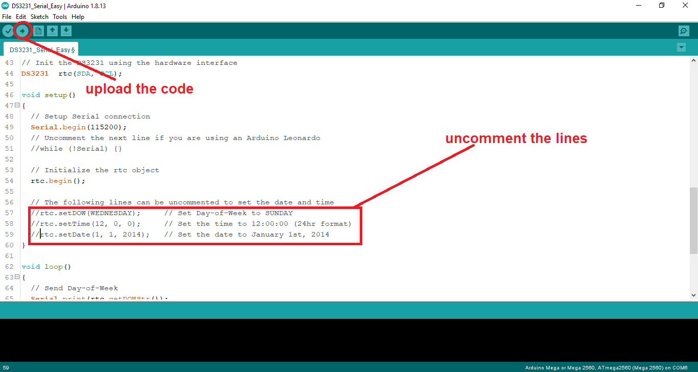
First open Arduino ide, click on file, next go to examples, search for DS3231, open DS3231 and select arduino and open DS3231_Serial_Easy example. Now scroll down go to 57th line of the code and uncomment the code from 57 line to 59 line and set present day, present time, present date. Now upload the code to arduino mega now open the serial monitor and set the baud rate to 115200 and you u would seeing the date, time, day and all. Now close the monitor and and comment lines which we have uncommented and again upload the code. That's it time, date, day.....etc are all set now you would be seeing the correct time.
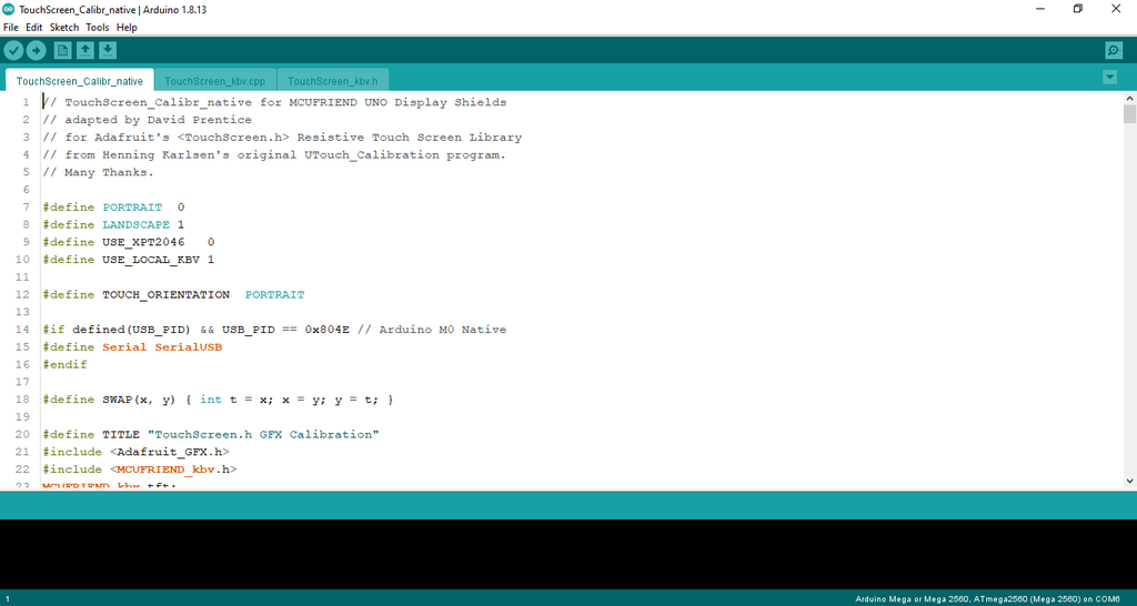
Step 6: Touch Calibration for Screen
ข้อมูล Frontmatter ดั้งเดิม
apps:
  - "1x Arduino IDE"
  - "1x Adafruit GFX Library"
author: "ROCKSTAR13"
category: "Communications, Displays"
components:
  - "1x Arduino Mega 2560"
  - "1x GSM/GPRS Module (SIM800/SIM900)"
  - "1x 3.5-inch TFT Touch LCD (UI Display)"
  - "1x LiPo Battery & Boost Converter"
  - "1x Custom 3D Printed Case"
  - "1x Soldering iron (generic)"
  - "1x Solder Wire, Lead Free"
  - "1x Hot glue gun (generic)"
  - "1x Programming Cable, USB"
description: "A professional and advanced smart-device project that uses an Arduino Mega 2560 and specialized cellular logic to build a high-performance custom smartphone prototype capable of basic telecom features and open-source development."
difficulty: "Intermediate"
documentationLinks: []
downloadableFiles:
  - "https://github.com/shiva1485/Arduino-Based-Phone.git"
encryptedPayload: "U2FsdGVkX1/JE0m/Ow+QmW+EouXi7mn4rMjbCFHMYWf6RBKOjOsfuVGTQdxl1Sb1/j1i9LZm5fFXwTUIzyCubSd2Aew/WXJBSnCZDc3c98VTZoeJPjmoo/BjBwZNaMIS"
heroImage: "https://cdn.jsdelivr.net/gh/bigboxthailand/arduino-assets@main/images/projects/arduino-based-phone-56d407_cover.jpg"
lang: "en"
likes: 2
passwordHash: "e403404307e6b2594b279f6d534acc2c23f6bf9d6f8c245087e4ebd169232148"
price: 2560
seoDescription: "An advanced and playsomely interactive Arduino-Phone-Sync for beginners interested in Arduino cellular-telecom and display-ui projects."
tags:
  - "arduino-smartphone-prototype"
  - "gsm-module-sync"
  - "tft-display-dispatch"
  - "open-source-telecom"
  - "arduino-mega-2560"
  - "intermediate"
title: "Arduino Based Phone"
tools: []
videoLinks:
  - "https://www.youtube.com/embed/wpyd6bKWxIQ"
views: 856