Design and Development of a High-Precision RPM Measurement System using Single Shot Detection and Laser-IR Hybrid Techniques
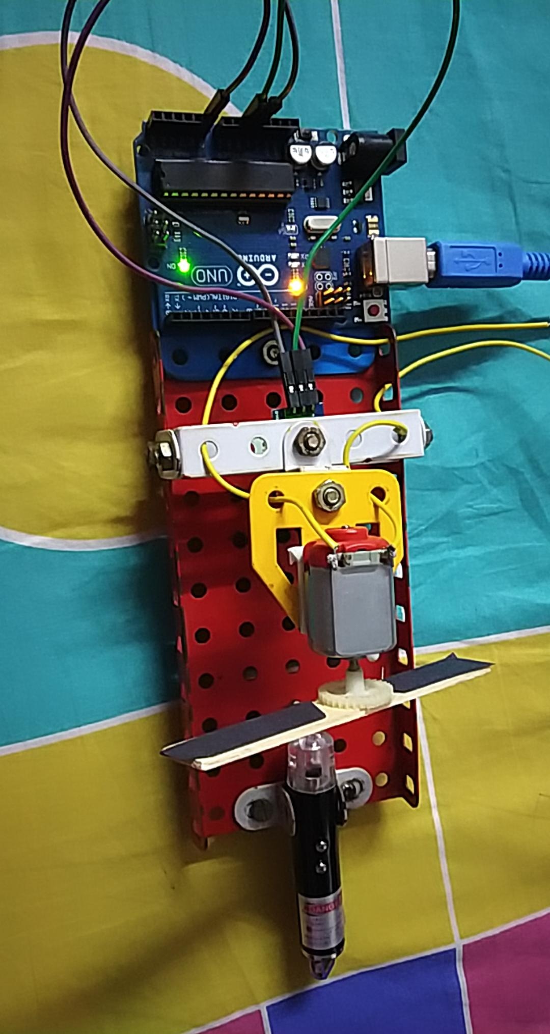
In the world of embedded systems, accurate measurement of motor or rotating object speed (tachometry) is fundamental for controlling and analyzing the performance of mechanical systems. This project involves developing an RPM measurement system from scratch, focusing on using simple yet highly effective components to achieve the most precise measurement values through the application of an Arduino board, an infrared sensor (IR Sensor), and a crucial component: a red laser pointer.
Physical Principles and Sensor Operation
The interesting aspect of this project lies in choosing a "red laser" as the light source. The important technical reason is that red wavelength laser diodes emit a sufficient amount of infrared radiation (IR Radiation). General IR sensors can detect this signal in the form of an analog voltage (Analog Voltage). Whereas blue or green lasers have very low IR interference signals, causing the values read from the Analog port to be almost zero, which is insufficient for processing.
The detection process occurs when the laser beam is interrupted (Beam Interruption) by the rotating motor blade:
- Normal State: The laser beam continuously strikes the IR sensor. The sensor sends a predetermined voltage level to the Arduino.
- Interrupted State: When a blade moves to block the light path, the voltage immediately drops to a low state (Low state).
- Continuous Rotation: When the blade moves out of the light's path, the laser light strikes the sensor again, generating a pulse (Pulse) signal that corresponds to the rotation speed.
Single Shot Detection Algorithm: Redefining Speed and Accuracy
The most prominent feature of this project is the coding with a newly developed algorithm called "Single Shot Detection" which is designed to solve the latency problem in traditional RPM meters that typically count the number of pulses within one second before calculating.
Code Logic: This algorithm works by measuring the "Time Interval" (Time Interval) between each interruption of the laser beam (Inter-pulse duration), using a function that measures time values at the microsecond level. When the system detects one beam blockage, it means the blade has moved $1/n$ of a complete rotation (where $n$ is the number of blades).
$$RPM = \left( \frac{1}{\text{Time difference in minutes}} \right) \div n$$
With this Single Shot calculation method, the system offers the following capabilities:
- Processing Speed: Can output accurate RPM values in less than 40 milliseconds.
- High Resolution: Provides accurate decimal values up to 2 places, which is rare in systems using inexpensive sensors.
- Adaptive Response: The system can detect speed changes instantly with every $1/n$ rotation, making it highly responsive to motor acceleration or deceleration in fractions of a second.

Result Analysis from Serial Monitor
From the test results image with a DC motor (DC Motor) operating at 5V, it can be seen that the system displays results continuously and stably. The data refresh rate (Output Screening Rate) is approximately 2 times per second, which is sufficient for real-time status monitoring. The obtained RPM values are stable and reflect the algorithm's efficiency in effectively filtering out noise.
This project is a good example of leveraging the potential of seemingly simple hardware, combined with well-designed software, to create an industrial-grade measurement tool. I encourage fellow developers to build this project and experiment with different types of motors to observe the differences in results. If you have any questions or suggestions for further developing this algorithm, please feel free to share your thoughts in the comments.
Follow my new projects and Arduino innovations at: YASH36 Project Hub
Happy Making and Stay Safe!