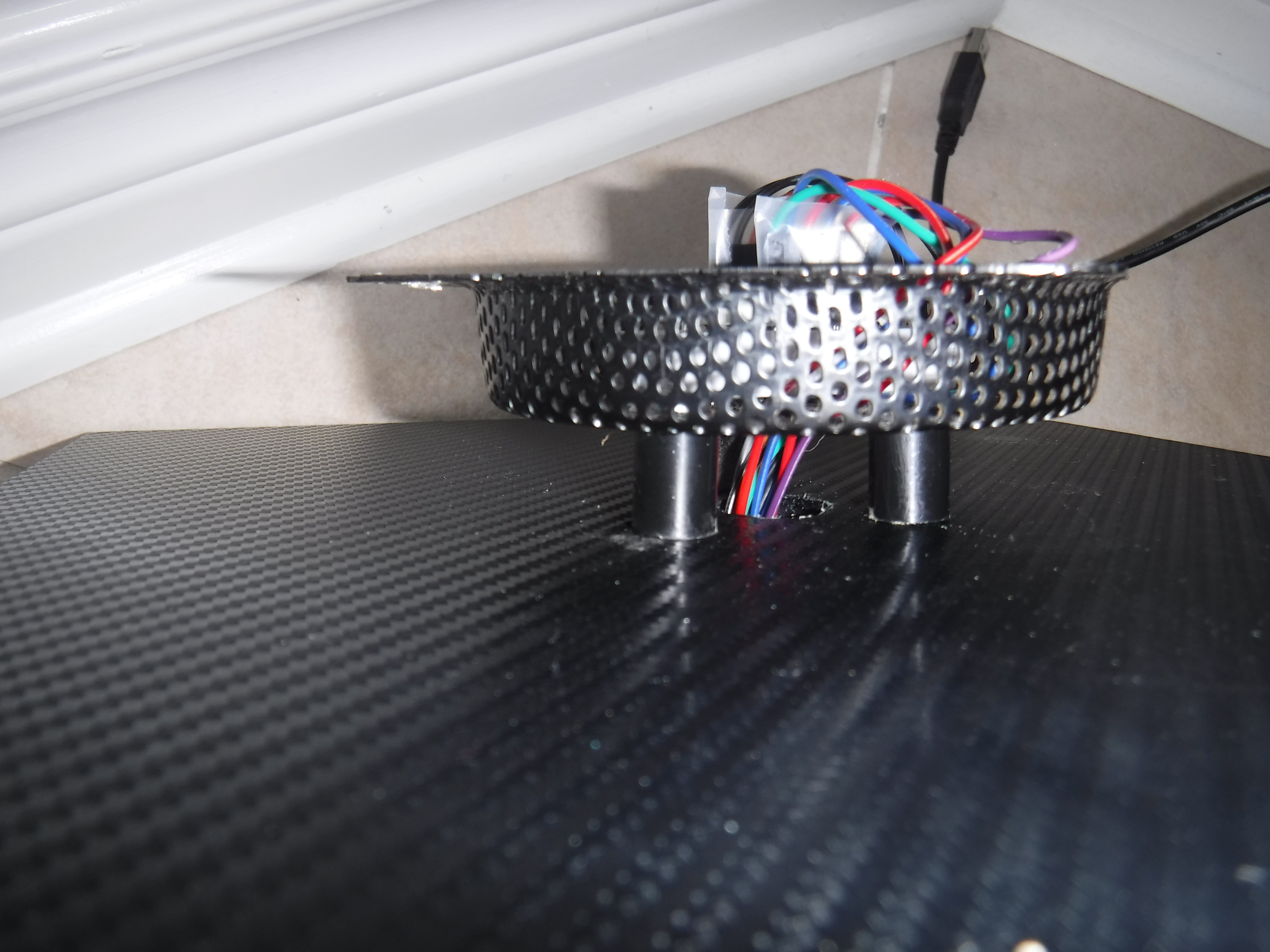
This project is one of which I have been waiting to do for a very long time. This project can also be used as just a simple clock without the rotor. The clock is housed in a simple metal dish that I never used. The wires are fed through a hole to the rear, in which has the Arduino and the RTC securely mounted.
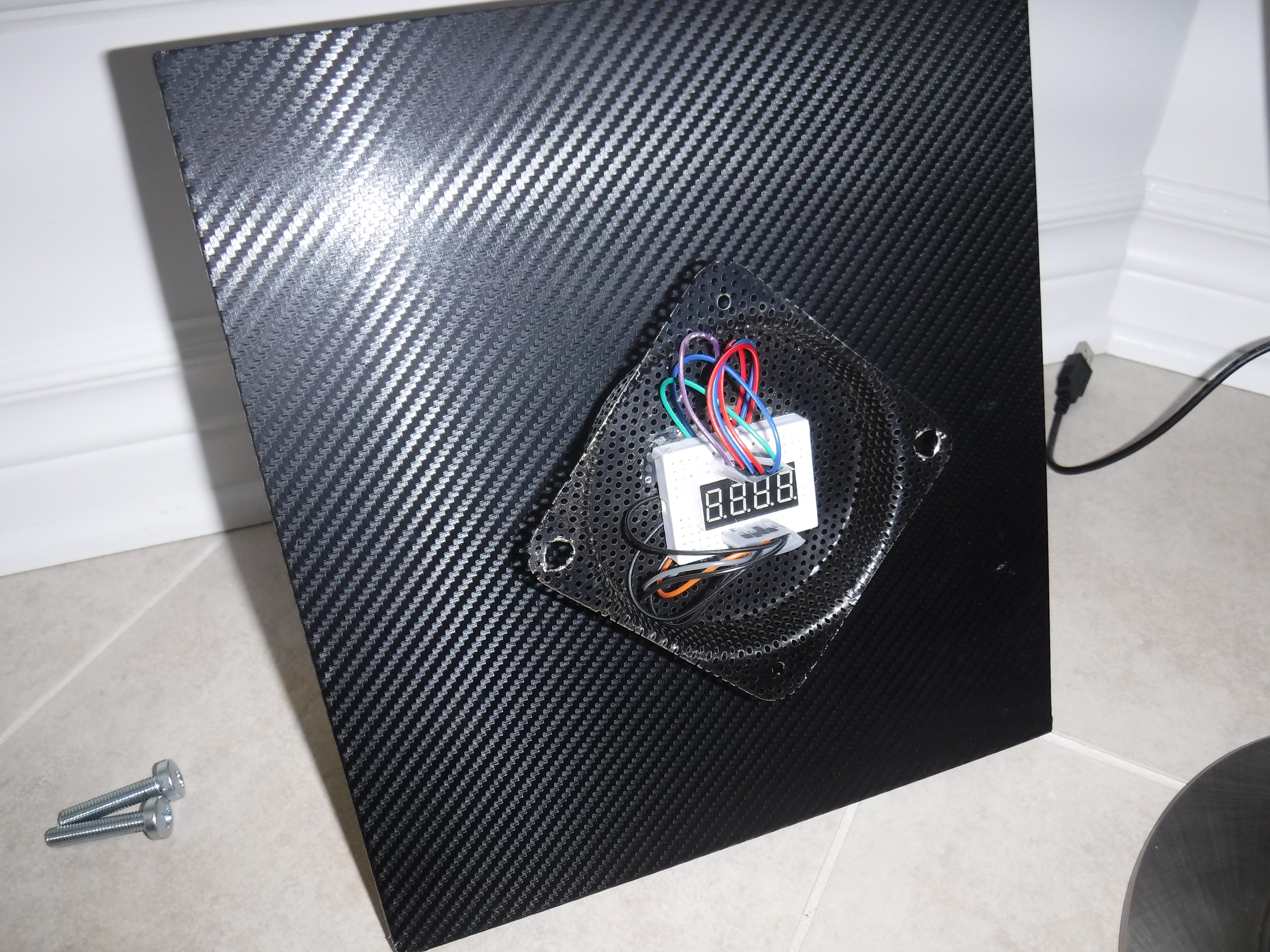
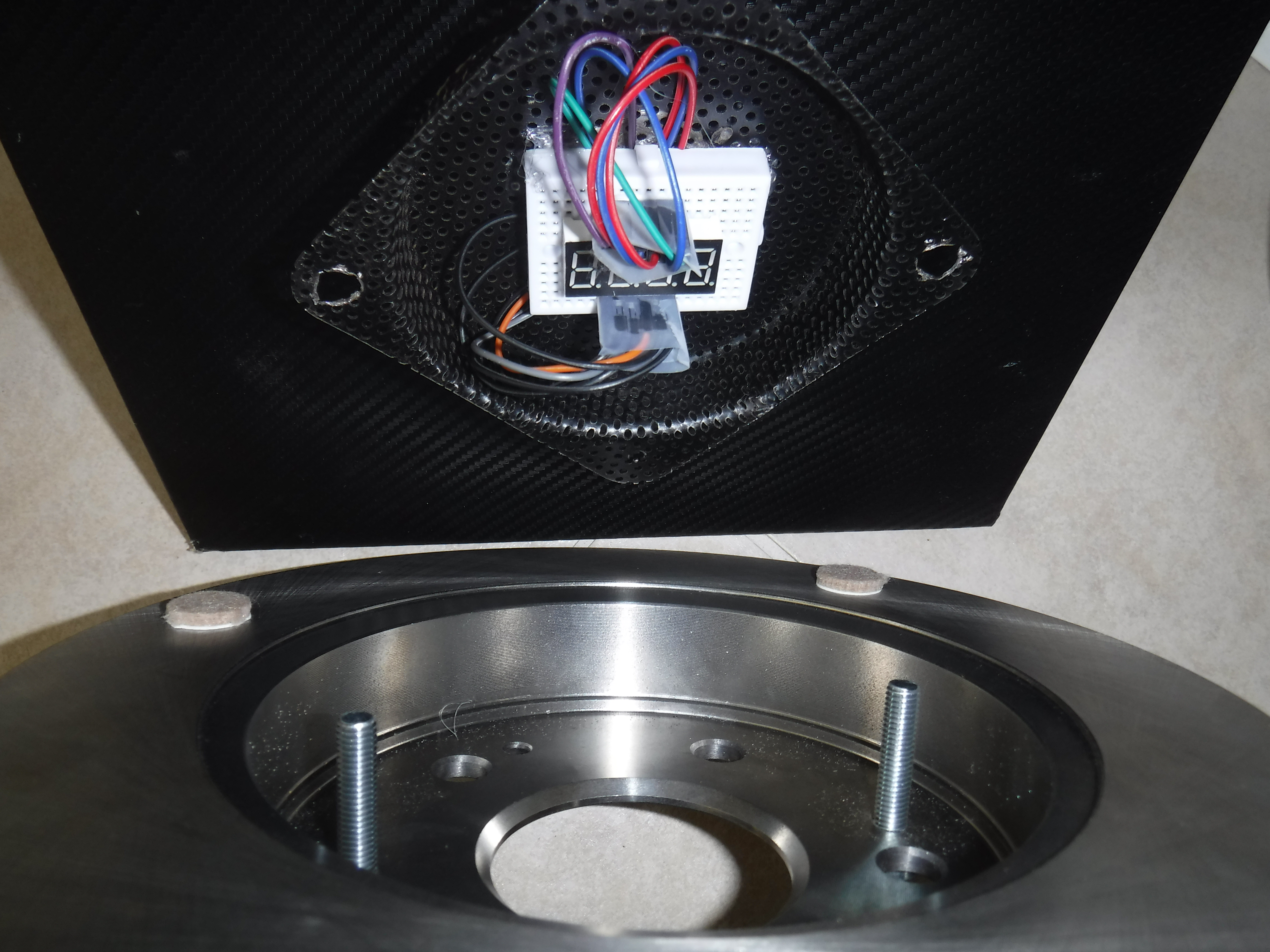
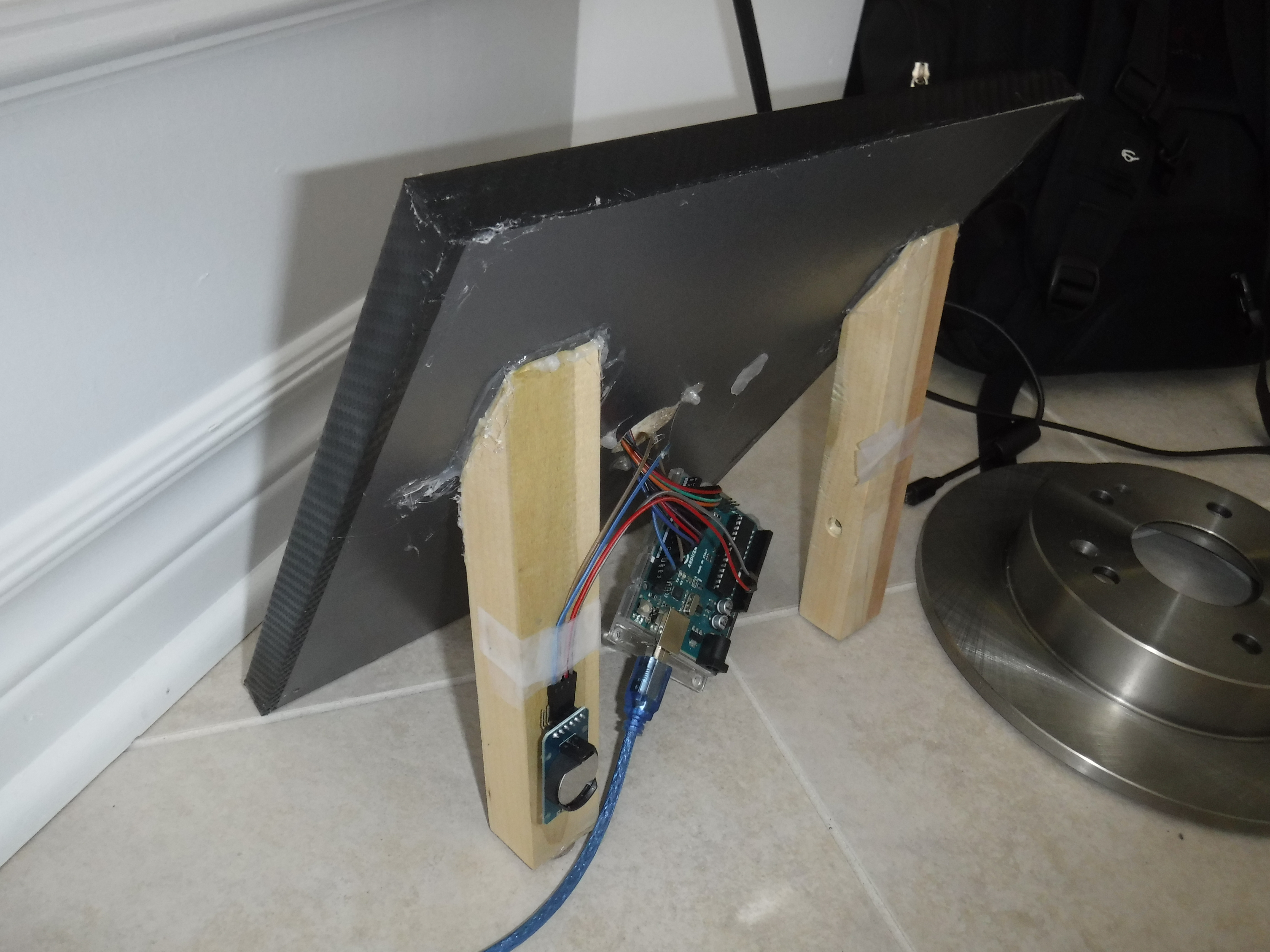
The base is a 1/2 thick piece of wood (make sure it can support the weight of your rotor) That is then wrapped with a carbon fiber vinyl tucked around the edges. We then have 2 1x1-inch wood legs are then cut to an angle of 50 or 45 degrees, then glued to the rear as support (see last picture). Your metal plate/dish is then firmly screwed in place with very durable screws (any type except machine ones). This point is where it gets tricky, as you must now wire up the clock to the front with your wires going through the back to the arduino that is mounted with the aid of double stick tape. Once you have finished the wiring you will want to clean up all glue strings and other debris from the face and back. Now mark your holes to mount the actual rotor screws, then drill them through your metal plate ensuring that you do not drill through the wood below. If you decide to buy the exact same rotor as I did there are 2 pre-tapped screw holes ready for our bolts to go through, and penetrate the earlier drilled metal plate mounting holes. Tighten the screws in so you have your screws going through your holes in the rotor then through the ones in the plate.
EXPANDED TECHNICAL DETAILS
Automotive Kinetic Sculpture
This project repurposes a physical automotive brake rotor into a unique, high-torque industrial clock.
- High-Torque Stepper Drive: Since a metal brake rotor is extremely heavy, a standard clock movement is insufficient. The Arduino uses a NEMA 17 stepper motor and an A4988 driver to move the rotor "Hand" with high precision.
- Chronometric Microstepping: The firmware implements 1/16 microstepping to ensure the second-hand moves with a smooth, silent sweep rather than the audible "Clicks" of a typical quartz movement.
Design
- RTC Synchornization: Uses a DS3231 I2C RTC to ensure the clock remains accurate even during power outages, with the Arduino automatically homing the rotor position upon startup.