Don't mind the look of it but it works very fine. I used the Arduino Nano as the programming board for the project. This project is ideal for beginners who want to learn how to work with DHT family sensors and manage display output on an LCD using the I2C communication protocol.
Main Components Used
- Arduino Nano: A small but powerful microcontroller board, offering high flexibility for embedded projects.
- DHT11 Sensor: A popular sensor that measures both humidity and temperature, outputting data as a single-bus digital signal.
- 16x2 LCD with I2C Module: Using an I2C Module is crucial as it significantly simplifies wiring. Instead of 6-10 wires, only 4 wires are needed (VCC, GND, SDA, SCL), saving a lot of time and reducing potential errors. If you don't have an I2C module, believe me, you need to buy it; it saves a lot of wire and effort.
Setting Initial Time in the Code
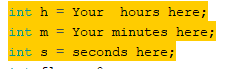
For this project, the clock system operates at the software level. Therefore, before uploading the program to the board, you need to define the initial time for the variables in the header section of the code so that the clock starts running from your desired current time.
In-depth Details and Technical Troubleshooting
I used the Simple DHT library, which makes working with the DHT11 sensor easier by simplifying the reading of raw data signals and converting them into usable numerical values.
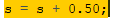
Clock Calibration: During testing while running the program on an Arduino Nano, I discovered an interesting issue: the clock ran too fast, approximately 1 second per cycle. To resolve this in software, I fine-tuned the second's increment rate. I changed the increase rate of seconds to 0.50 to align with the actual cycle occurring on my Nano board, as when I finalized it with Arduino Nano it started moving 1 second faster (idk why). This made the displayed time more stable and accurate.
Wiring Diagram
Connecting the various components is quite straightforward, and to me, the wiring along with I2C is simple. You can edit the code if you want to use a normal LCD display.
1. Connecting the DHT11 Sensor
So for the connections, I used a DHT11 with 4 pins, and here's its pinout:
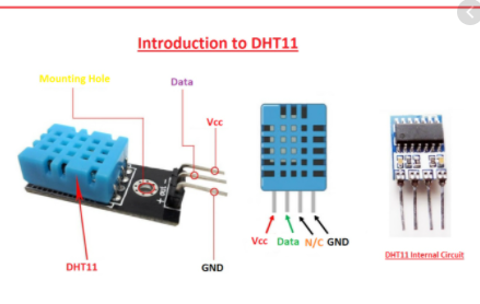
- VCC: Connect to the Arduino board's 5V power supply.
- GND: Connect to the board's Ground.
- Data Pin: Connect to Digital pin 11 (as per the code).
2. Connecting the LCD (via I2C Module)
- VCC: Connect to Arduino 5V (same for the DHT11 sensor).
- GND: Connect to Arduino GND (same for the DHT11 sensor).
- SCL (Serial Clock): Connect to pin A5 of the Arduino Nano.
- SDA (Serial Data): Connect to pin A4 of the Arduino Nano.
Note: Pins A4 and A5 are dedicated pins for I2C communication on the Arduino Nano (ATmega328P) board.
This is all for the project. This was my first upload; pardon me if any mistakes.
Conclusion and Developer's Comments
This project serves as a good first step for learning Embedded Systems. The most important thing isn't just connecting wires correctly, but understanding how each component communicates, for example, why I2C is necessary, or troubleshooting software-based Clock Drift as I encountered.
In the future, I am thinking to upgrade it with a few more things, like adding an RTC (Real-Time Clock) module, such as the DS3231, to allow the time to run independently even without power, and possibly add buttons for setting the time without modifying the code.
I hope this project is beneficial and inspires everyone who is starting in electronics.
Thanks,