Project Perspective
Arduino Control Center Thermostat Example is a fundamental layout for anyone just starting their journey with home automation and environmental control. By using a specialized software suite called Arduino Control Center (ACC) and high-precision temperature sensors, you can build a more organized and easy-to-use thermostat for your home.
Technical Implementation: ACC and Sensors
The project focuses on creating a high-performance and user-friendly thermostat:
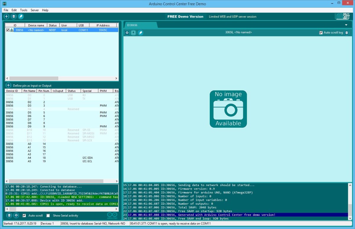
- Software Control layer: The Arduino Control Center (ACC) software provides a graphical user interface for configuring and managing your thermostat's settings and logic.
- Sensing layer: Using two DS18B20 Temperature Sensors, you can accurately monitor the temperature in different zones and trigger the appropriate relay response.
- Actuation layer: A 4-Channel Relay Module allows the Arduino to turn on or off various heating or cooling appliances based on the thermostat's logic.
Hardware Infrastructure
- Arduino Uno: The "brain" of the thermostat, managing the ACC software connection and coordinating sensor and relay activities.
- Arduino Ethernet Shield: Connects the Arduino to your local network, allowing for remote monitoring and control over UDP or HTTP.
- DS18B20 Temperature Sensors: Providing high-precision digital temperature readings.
- Relay Module: Effectively isolates and controls high-voltage/current home appliances with a low-voltage signal.
- Micro-USB/Ethernet Cable: Use to program the Arduino and connect to your computer or local network.
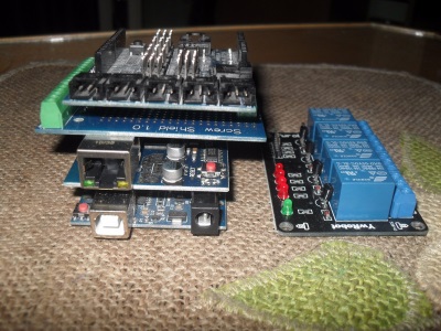
Required hardware:
- Arduino UNO
- w5100 Ethernet shield
- 2 x DS18B20 temperature sensor
- Screw shield
- 4 channel relay board
- Dupont wire jumpers male-female, female-female
- and(or) Sensor shield (for easier connecting and following instructions)
Required hardware without connected DS18B20 temperature sensors.
DOWNLOAD LINUX UBUNTU(17.04 , 32bit)
Entire project does not require soldering, all connections are made with wires and shields.
Arduino Control Center zipped file, unpack and run the application, portable no installation.
Setup and Interaction Step-by-Step
The setup is designed to be clear and efficient:
- Initialize ACC: Install the Arduino Control Center software and complete the initial setup.
- Connect Sensors and Relays: Correctly wire the two DS18B20 sensors and the relay module to your Arduino.
- Configure ACC: Use the ACC software to configure the input (sensor) and output (relay) pins and set the desired temperature thresholds.
- Remote Management Integration: Use the ACC's HTTP or UDP server features to remotely monitor and control your thermostat from a web-based dashboard.
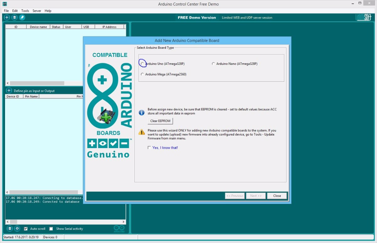
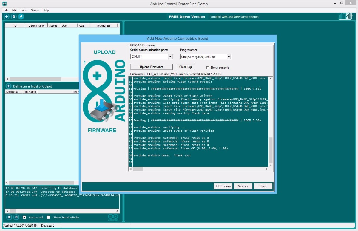
Configure Arduino Uno with Ethernet shield for use:
- Select Arduino board type
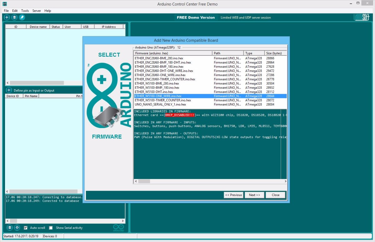
- Select firmware for Arduino board type
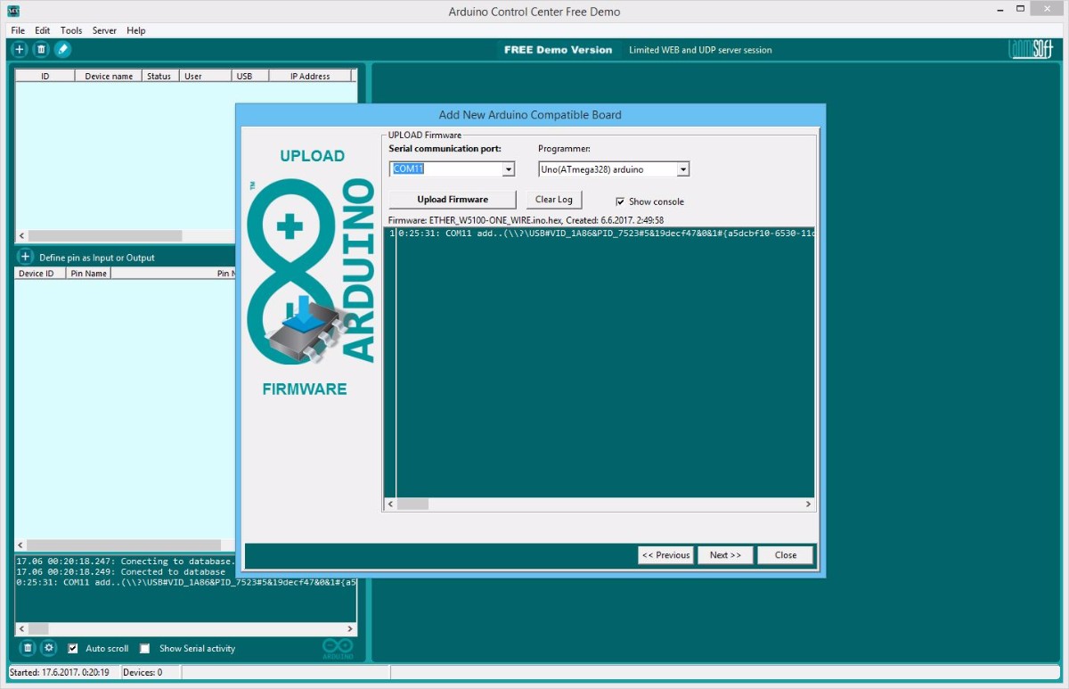
- Select communication serial port
- Upload Arduino compiled sketches (firmwares) with built in uploader, no Arduino IDE required
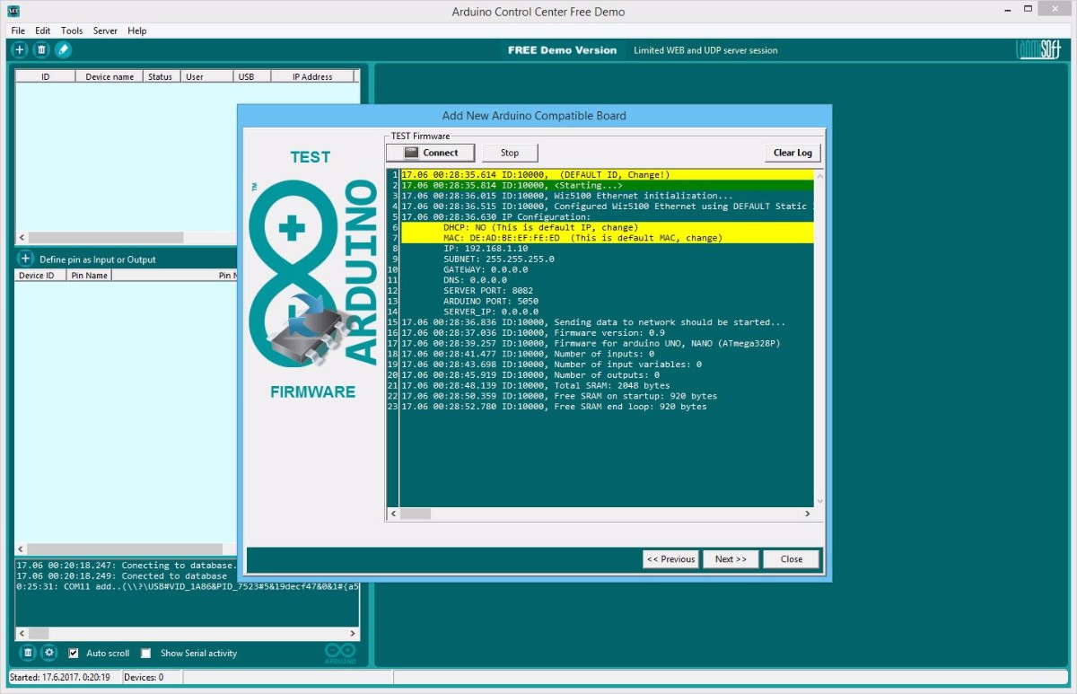
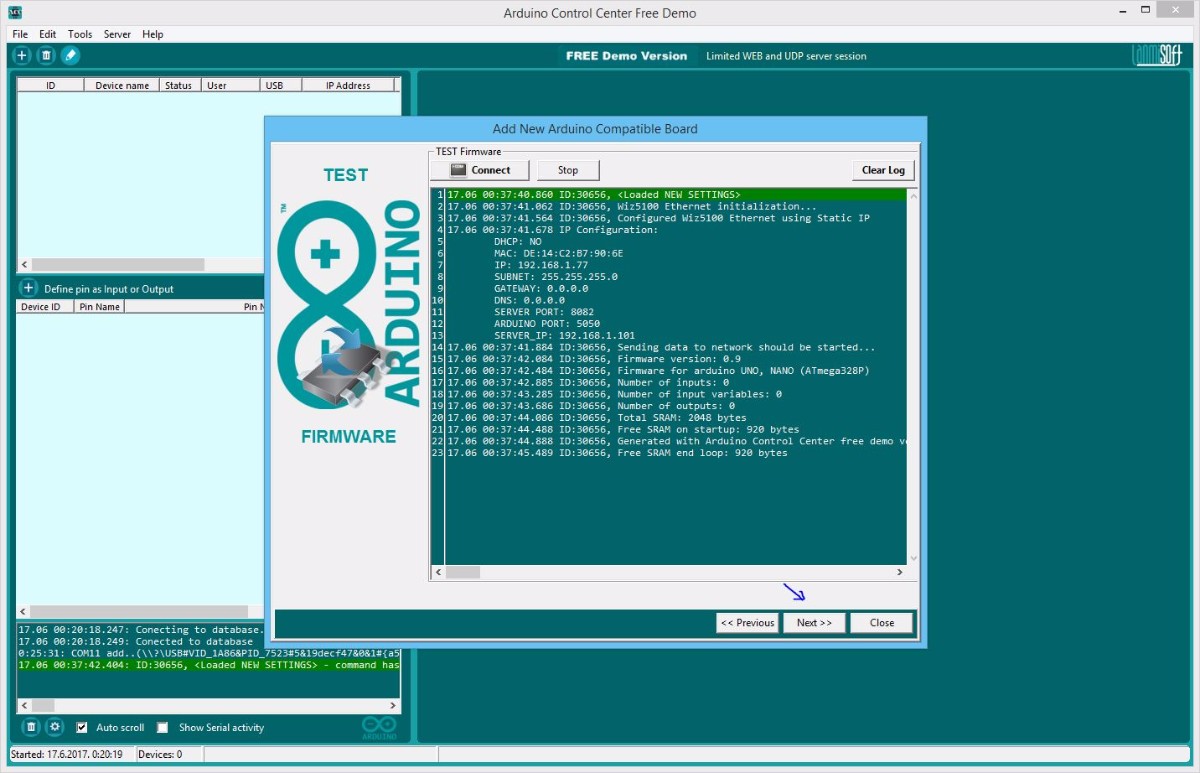
- Test uploaded firmware, read messages
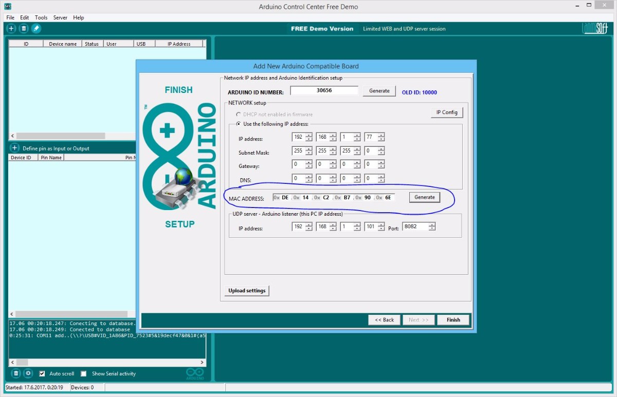
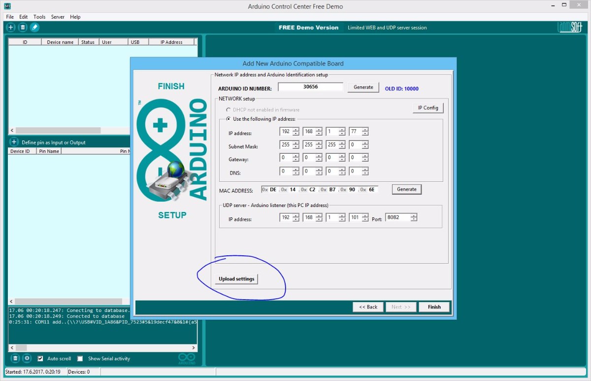
- Generate Arduino ID number, required
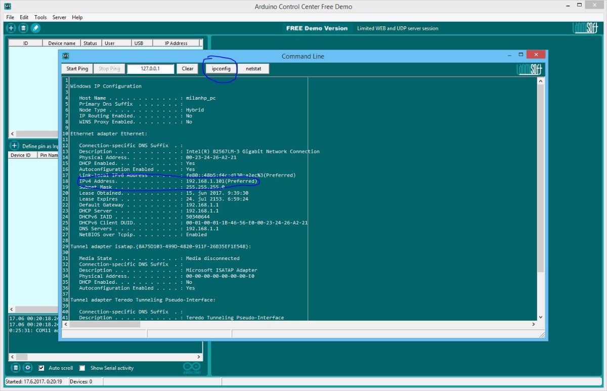
- Find your PC IP address, required for network shield setup
- Set Arduino PC IP address, has to be within your LAN (local network) range. DHCP for Arduino UNO is disabled!
- Generate Arduino MAC address, required! Must be unique in LAN!
- Set UDP (Arduino server) IP address - this is YOUR PC IP address in this example!
- Upload ID and network configuration
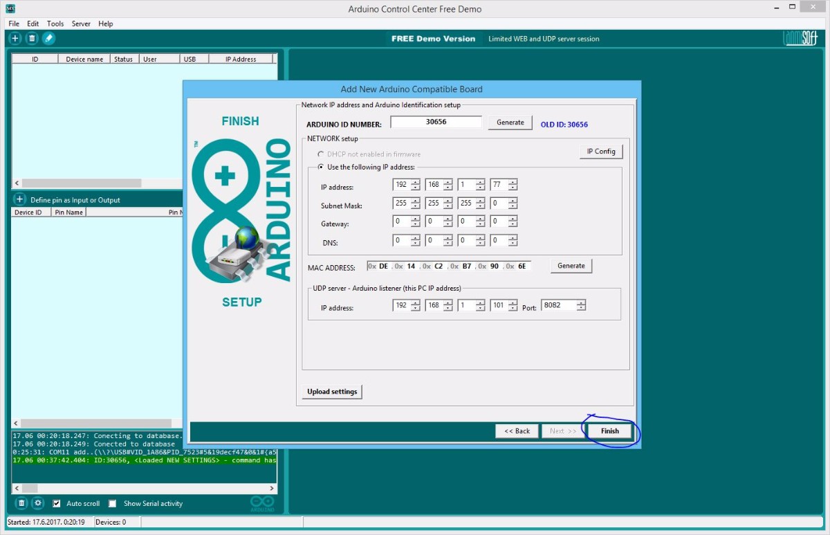
- View Arduino board configuration
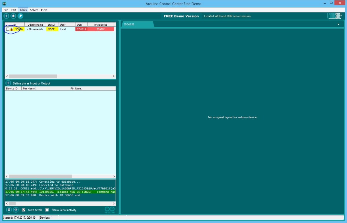
- Finish Arduino configuration and add device to the ACC system
- Click on checkbox in the list in order to open serial communication
- VOILA! You are ready to configure Inputs and Outputs!


Configure Inputs and Outputs:
- Double click on pin list (or right click-Configure pin) and add DS18B20 sensor (2 times, pin D6 and D7
- Double click on pin list (or right click-Configure pin) and add relays (4 times, pins A0-A3, see image)
- Right click on relay and set the triggering rule for thermostat
- Triggering rule preview
- If you relay board (like in this example) trigger relay with LOW, you can INVERT output in order to show real relay status
Required hardware with connected DS18B20 temperature sensors and relay board:
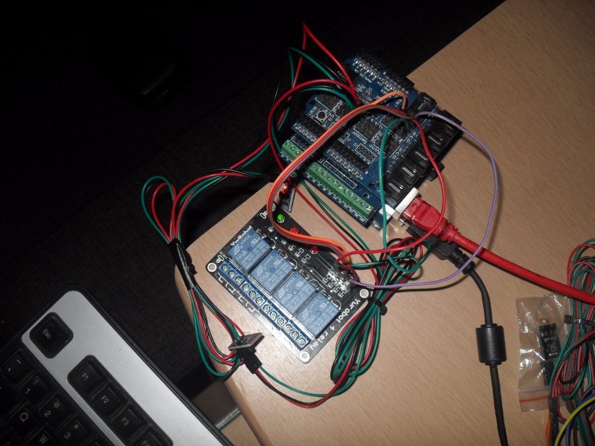
- Relay board: A0-A3, analog pins will be set as digital outputs when you set pin as DIGITAL
- DS18B20 data pin(DQ): First D6, second D7
VCC and GND for sensors connect to sensor shield V and G contacts (if you use sensor shield, or depends of what kind of hardware you use).
Setup and start HTTP and UDP servers:
- Open servers page
- Set UDP and HTTP port( default 8082 and 80)
- Start servers
- If setup is ok you should see your Arduino IP address
- If you relay board (like in this example) trigger relay with LOW, you can INVERT output in order to show real relay status.
Create rules for relays:
- Right click on output(relay) and click on "Rule editor" menu item
- Create rule with available DS18b20 sensors
- Rule mark on output(relay) image
- Login to web page
- Web preview for created configuration
- Toogle relays over network. If Arduino device has serial and network connection, serial connection has higher priority
Future Expansion
- OLED Status Display Integration: Add a small OLED display to show real-time temperature readings and relay status.
- Multi-Zone Temperature Monitoring: Add more DS18B20 sensors to monitor even more zones within your home.
- Schedule-Based Control Integration: Use the ACC software to set up custom heating or cooling schedules based on time of day or weekend.
- Email/SMS Alert Dashboard: Use the ACC software to receive email or SMS notifications if certain temperature thresholds are exceeded.
Arduino Control Center Thermostat Example is a perfect project for any electronics enthusiast looking for a more interactive and engaging home automation tool!