The whole idea for this project started when I was looking at an IKEA turntable, which is normally used for Chinese meals:
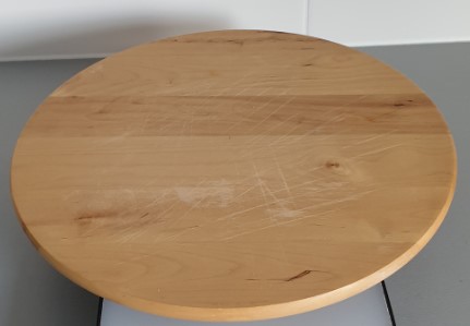
The idea was simple: why not make this thing turn automatically using a stepper motor and control it with an ARDUINO.
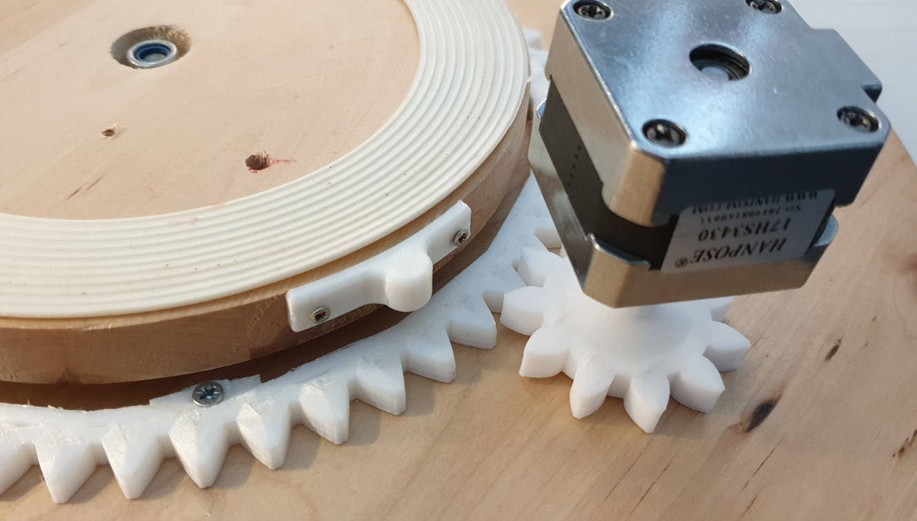
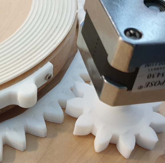
So, I started to 3D print some gears that would fit with a stepper motor that I already had available.
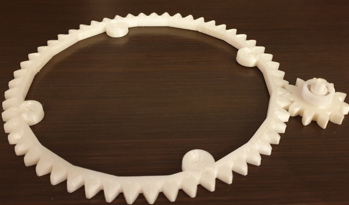
It soon turned out that this construction was not going to work, simply because the stepper motor was not strong enough to move the mass of the wooden turntable.
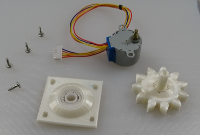
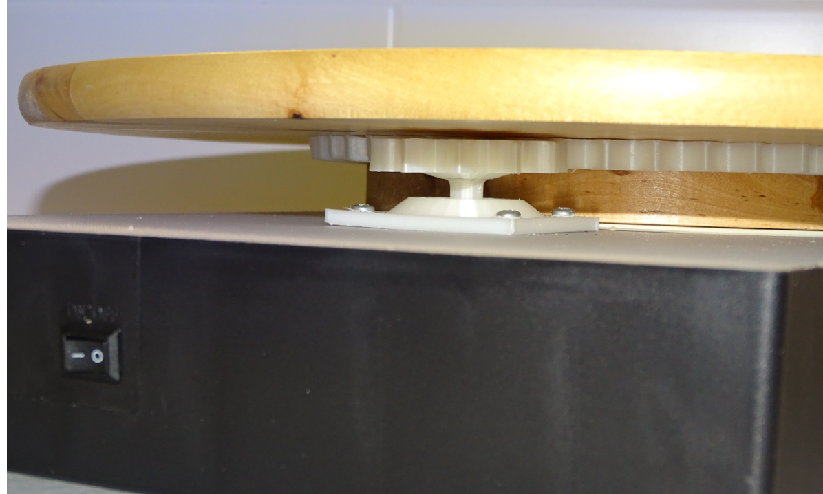
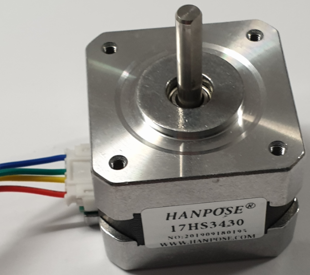
So I got myself a more powerful stepper motor, a NEMA 17 HS 34:
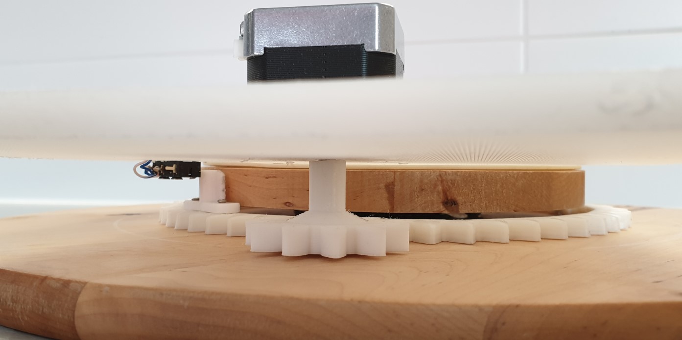
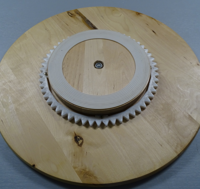
Although this construction worked (with pain), the stepper motor was barely able to turn the table due to the heavy wooden table and the friction in the plastic gears.
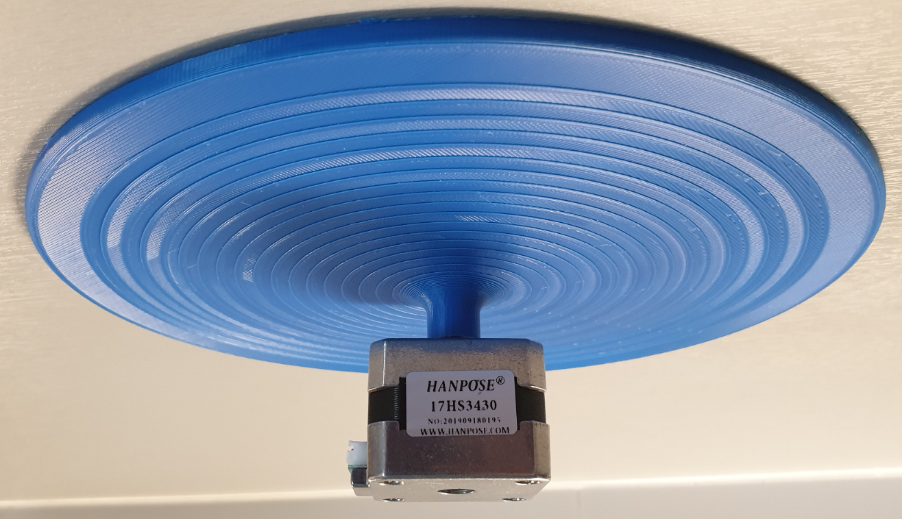
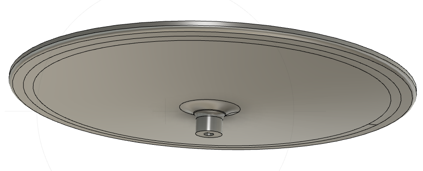
Therefor, I dropped the idea of using the IKEA turntable and 3D printed my own turntable which was much lighter and could easily be turned with the NEMA 17 stepper motor!
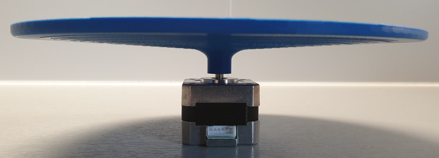
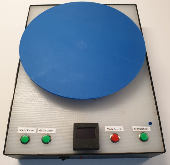
After building everything together this became the final result of this project:

Of course my ambition was more than just make an object turnaround 360 degrees!
I wanted to remotely control my SONY HX400 camera (wirelessly, via Bluetooth) and automatically take a photo every xx degrees. This of course with the aim to convert all the single 2D photographs into a 3D photo and further process the object for 3D printing.
Here you can watch the result: https://youtu.be/ci-9449n2nU
In the following tutorial, you will read how this project has been built.
I wish you good reading, and I hope it is inspiring to build something similar.
Things
Hardware components:
See Step 2 and 3
Common tools & test equipment
Software apps and online services:
- Arduino IDE
- Fusion 360
- CURA
- Autodesk Fusion 360
- ClickCharts Diagram and Flowchart
- EasyEDA
- Fritzing
Step 1: System Design
The Turntable design is shown in the below diagram:
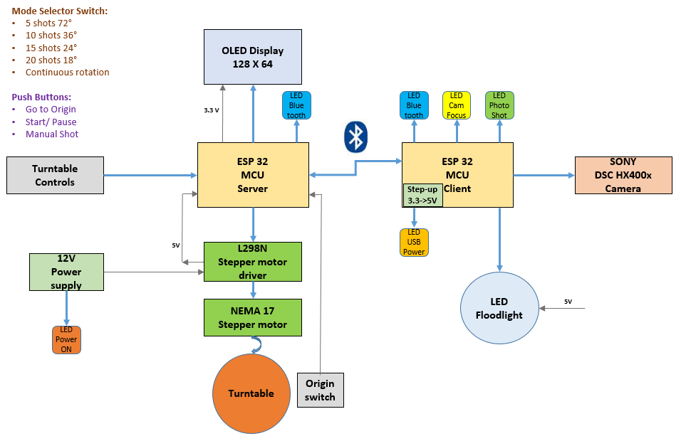
The system, basically consists of 2 main parts:
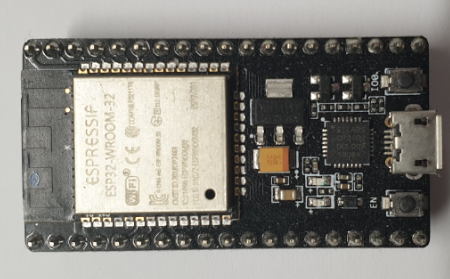
- The TurntableAssembly (TA) with a ESP32 microcontroller acting as server:
- The CameraControl Box (CCB) with an ESP32 acting as client:
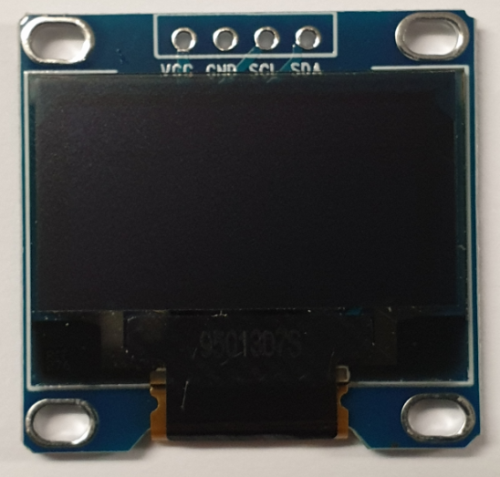
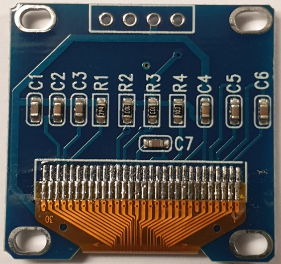
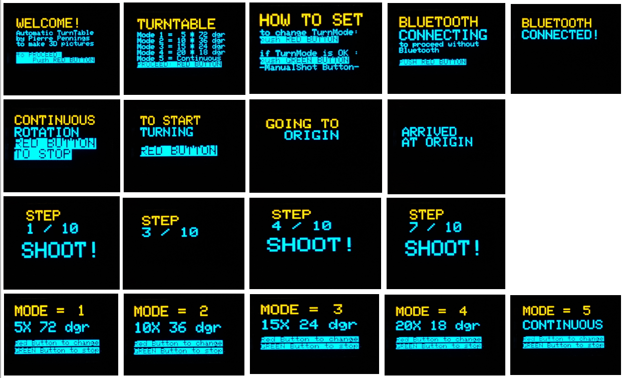
The TA is equipped with an 0, 96 inch OLED display, which together with a pushbutton forms the HMI (human machine interface) for the system:
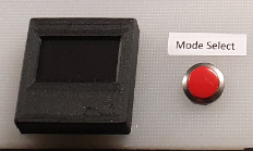
This HMI enables the user to select the turning modes of the turning table and to monitor the status.
The available turning modes are as follows:
- 5 shots at 72° steps
- 10 shots at 36° steps
- 15 shots at 24° steps
- 20 shots at 18° steps
- Continuous rotation
There are 3 green buttons that are used for actions such as:
- “go-to-Origin” which brings the turntable to a starting position determined by a mechanical switch (built underneath the turntable).
- “Start/Pause” used to restart the set up to initiate another turning mode
- “manual shot” intended to send a shoot command to the camera, but in the current design only used in the process for choosing the turning mode.
All electronics for the MCU as well as stepper motor and its driver are built in the turntable housing.
A blue LED indicates the status of the blue tooth connection to the camera client.
Power is provided with a 12V/3A power supply connected to the mains; a red LED indicates that power is switched on.
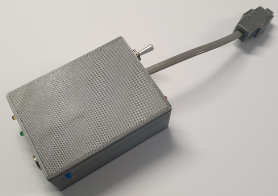
The CCB is a 3D printed box, that houses the ESP32, some LED’s (3mm) and a connector to the multiport micro USB plug of the SONY HX 400V camera. Power for the CCB is taken from the camera battery (3, 3V). The CCB also has a connector for a 3, 5mm plug that enables the on/off switching of a separate flood light LED for illuminating the object to be photographed.
The 3 LED’s (apart from the orange power indicator) have the following functions:
- YELLOW LED: indicating that the Camera FOCUS is being activated
- GREEN LED: indicating that the camera is getting the “SHOOT” command
- BLUE LED: indicating the status of the Bluetooth connection with the turntable server.
Step 2: Making the Turntable Assembly
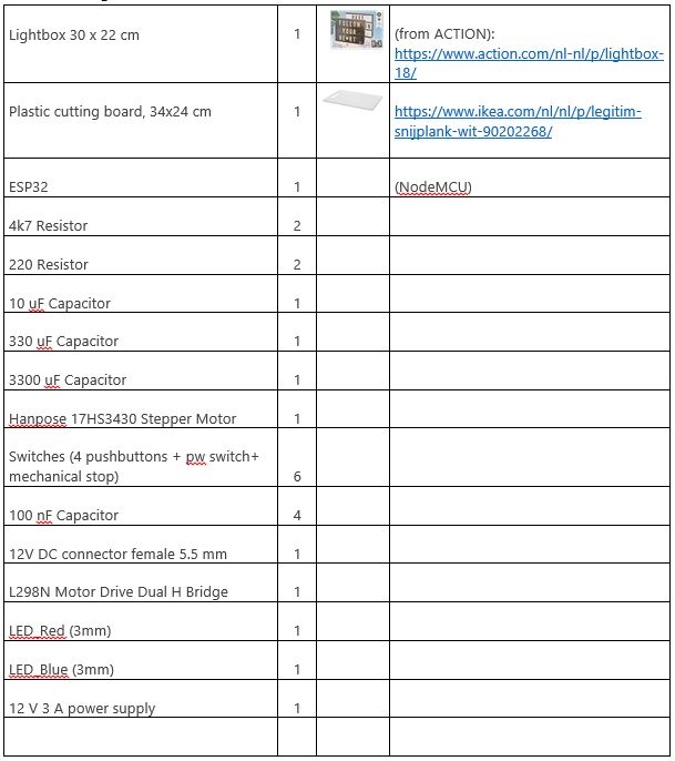
Things used
The following materials are used for the turntable:
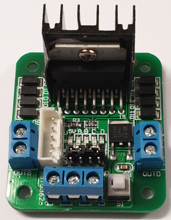
The Electronic Design
The electronic design is shown in the following circuitdiagram. The power supply is 12 V/3A. The internal 5V supply for the ESP32 is taken from the L298N motor driver while the 3, 3 V for the OLED display is taken from the ESP32 board.
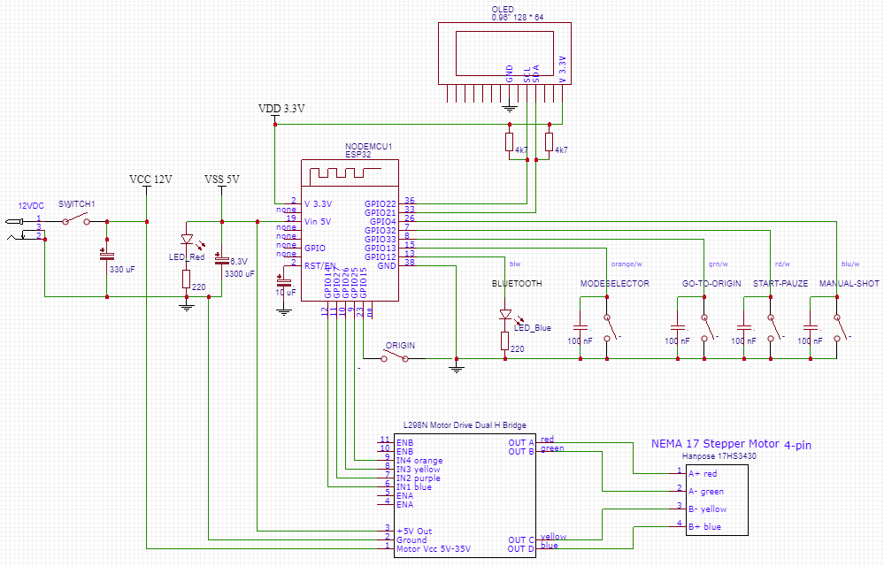
Above diagram is made using EasyEDA.
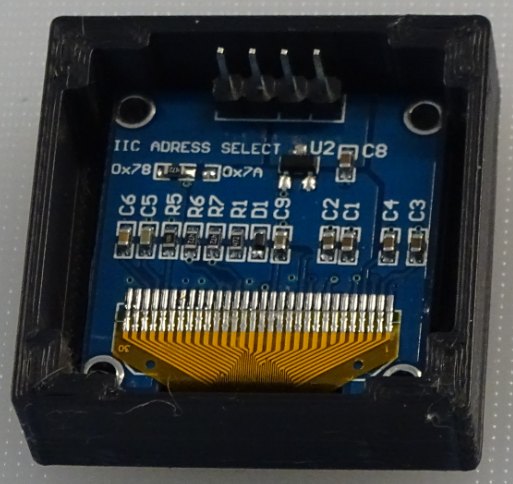
The 0, 96” OLED display has128 * 64 pixels and has been put in a 3D printed housing:
The NEMA 17 Stepper Motor and driver are depicted below:
EXPANDED TECHNICAL DETAILS: The NEMA Stepper Micro-Stepping
Spinning an object continuously is insufficient for 3D Photogrammetry scanning; motion-blur completely destroys the algorithm! The camera must be totally still. This project executes a brilliant, synchronized State Machine. It commands a massive stepper motor to index an item precisely, brutally halts it completely solid, then triggers a camera shutter remotely for a flawless capture sequence!
You absolutely cannot use a cheap, low-torque motor. It has zero positional accuracy.
- The project uses a massive NEMA 17 Bipolar Stepper Motor.
- The 200-Step Math Equation: Standard NEMA steppers have 200 physical steps per revolution. That means each step is a massive
1.8 degrees. If scanning a tiny miniature, the rotation is too jerky! - The C++ code commands the motor driver (like an A4988 Stepper Driver).
You can physically set "Micro-Stepping" jumpers on many drivers (
MS1, MS2, MS3). - This mathematically forces the driver chip to create intermediate steps electromagnetically using complex PWM voltage mixing!
200 Stepscan be transformed into3200 Microsteps per revolution!. The turntable then moves with incomprehensibly buttery smoothness at0.11 degrees!
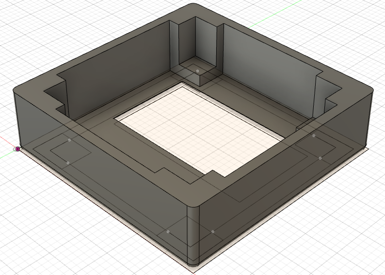
The Turntable plateau has been designed with Fusion 360 and printed on a Creality CR10S Pro. The borehole is also printed and fits exactly with the spindle of the stepper motor.
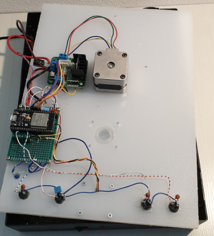
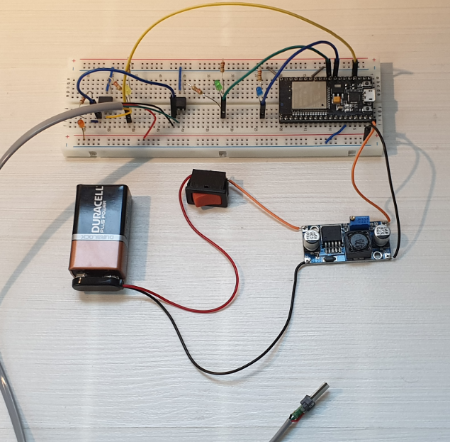
The breadboard set up used for testing and building the software with the ARDUINO IDE, is shown inthe following picture:
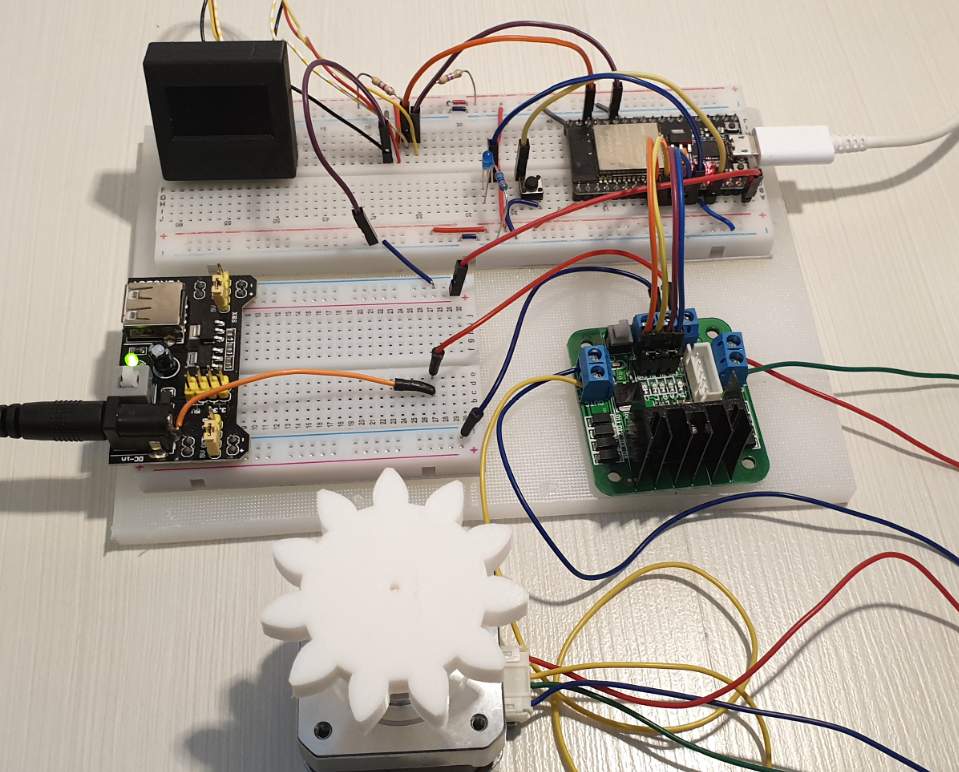
Note: the 3D printed plastic gear is part of the original construction idea, based on the IKEA turntable.
Mechanical and electrical assembly
The assembly of all mechanical and electronic parts is shown in the pictures below:

Note that the whole turntable requires only 1 cable to be connected, namely the 12V power cable. A separate opening is made in the box for (temporarily) connecting the micro USB plug of the ESP32 board, to be used in case of software updates.
The complete building plate has been cut out ofthe IKEA cutting board and made to fit in the ACTION box.
The Software design
The following flowchart shows the high level design of the turntable server software:
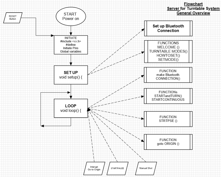
In the set up phase a number of Functions are called:
- Set up of the Bluetooth connection
- WELCOME (); //displaying a welcome message until the red button is pushed
- TURNTABLEMODES (); //displaying the possible turntable modes of operation
- HOWTOSET (); //displaying an explanation how toselect the turntable modes
- SETMODE (); //setting the turntable modes by pushing the red button and selecting with the green button
- ORIGIN (); //controlling the turntable to an origin position
The menus, displayed on the 0, 96” OLED display, will appearas follows:
The “LOOP” function itself is pretty short and is listed below:
void loop() {
 CONNECTION();
 switch (turnmode) {
     case 1:                   // Turnmode 1: 5 X 72 dgr)
       STARTandTURN();
       break;
     case 2:                   // Turnmode 2: 10 X 36 dgr)
       STARTandTURN();
       break;
     case 3:                   // Turnmode 3: 15 X 24 dgr)
       STARTandTURN();
       break;
     case 4:                   // Turnmode 4: 20 X 18 dgr)
       STARTandTURN();
       break;
     case 5:                   // Turnmode 5: CONTINUOUS
       STARTCONTINUOUS ();
       break;
                 }
}
The only things, that happen in the loop, are:
- Making the Bluetooth connection
- Running the selected turnmode (as selected during set up)
The complete ARDUINO sketch for the turntable server comprises about 600 lines of code. The complete listing is included as part of this tutorial, the ARDUINO code is provided with an ample amount of comments.
Step3: Making the Camera client
Things used
The following materials are used for the turntable:

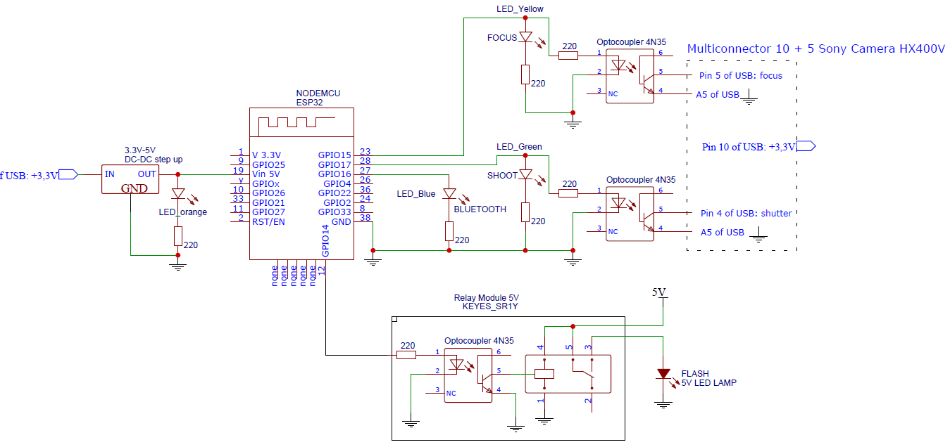
The Electronic Design
The power supply 3.3 V is directly taken from the Camera and converted into 5V, needed for the supply of the ESP32 (which internally generates 3.3V)
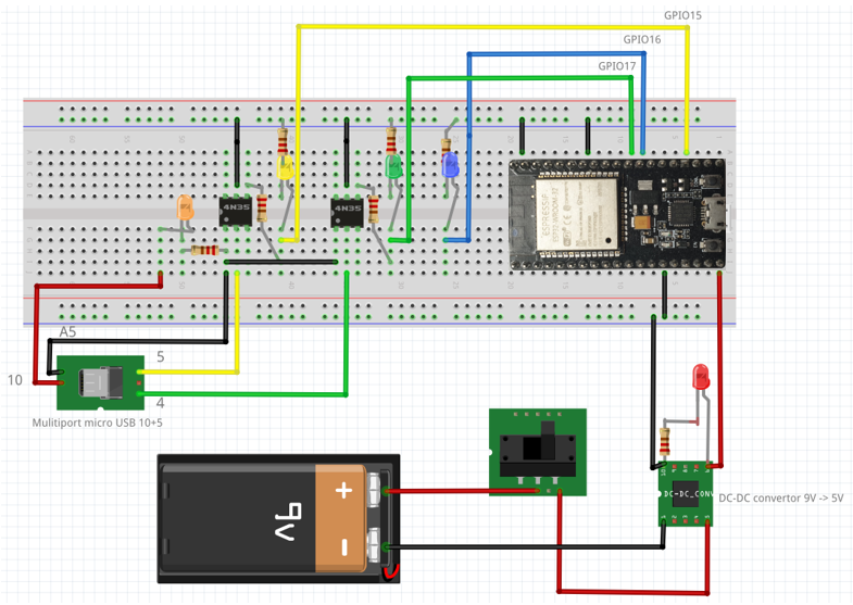
The Fritzing diagram looks as follows:
Nothing better than a good circuit diagram:
Interface with the HX400V SONY camera
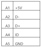
The Sony DSC HX400V Camera has a USB connector that looks like an ordinary micro USB connector (female) with 5 Pins and indeed a normal micro USB male connector can be plugged in for 5V charging and data transfer (see table below):
In fact the Sony connector is what Sony calls “a Multi/Micro USB Terminal that Supports Micro USB compatible device”, with 10 additional pins, that can be used for remote control of the camera.
In this project only the following pins of the multiport connector are used:
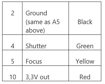
On the Internet, I found 3 sources for buying the relevant Multiport connector:
https://www.studio1productions.com/parts/sony-multiport-connector.htm
On the website of Studio1 you can also find more details on the Pin out of the multiport connector.
I bought mine from the Slovenian company MobileExcopter, who had the cheapest shipment option (EU mail).
I used a 4-wire telephone cable for connecting the connector to the ESP32. The soldering of the wires to the