Project Details: Development of a Smart Digital Clock System
In this project, I designed and built a digital clock system that accurately displays the current date and time via an LCD screen. The core of this system is the DS1307 Real-Time Clock (RTC) module, chosen for its ability to maintain time even when the main power supply is absent, making it ideally suited for applications in Embedded Systems requiring stable time data.
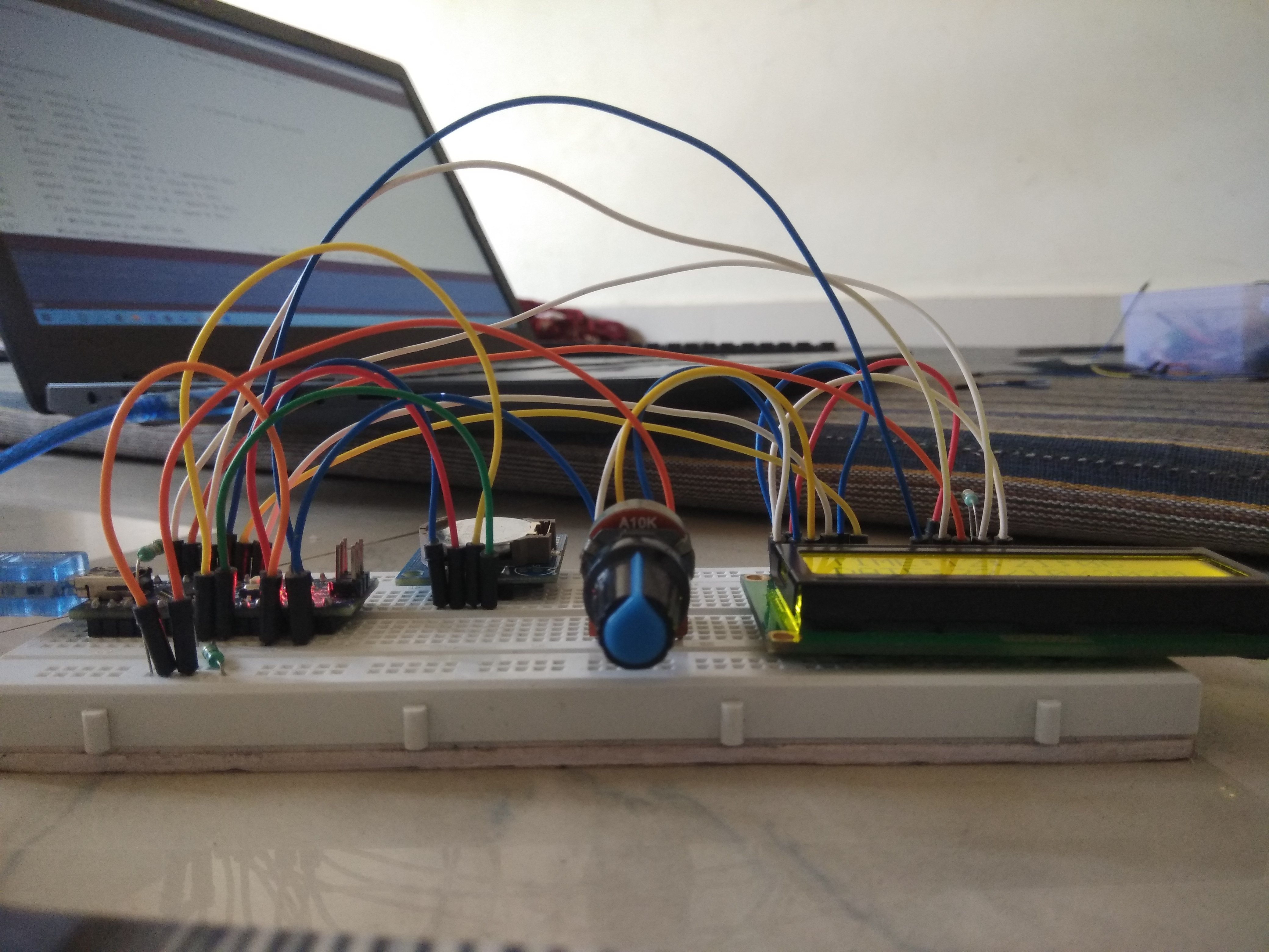
List of Used Components (Hardware Requirements)
To build this system, the following standard electronic engineering components are required:
- Arduino Nano: A small yet powerful microcontroller, using the ATmega328P chip as its main processor.
- DS1307 RTC Module: A Real-Time Clock module.
- HD44780 LCD Display (16x2): An industry-standard display screen.
- 10K Pull-up Resistors: Resistors used to pull up signal levels in the I2C bus system.
- Potentiometer (10K): For adjusting the contrast of the LCD screen.
- Breadboard and Jumper Wires: For prototyping the circuit.
- Push Buttons: Buttons for the interface to set time and date.
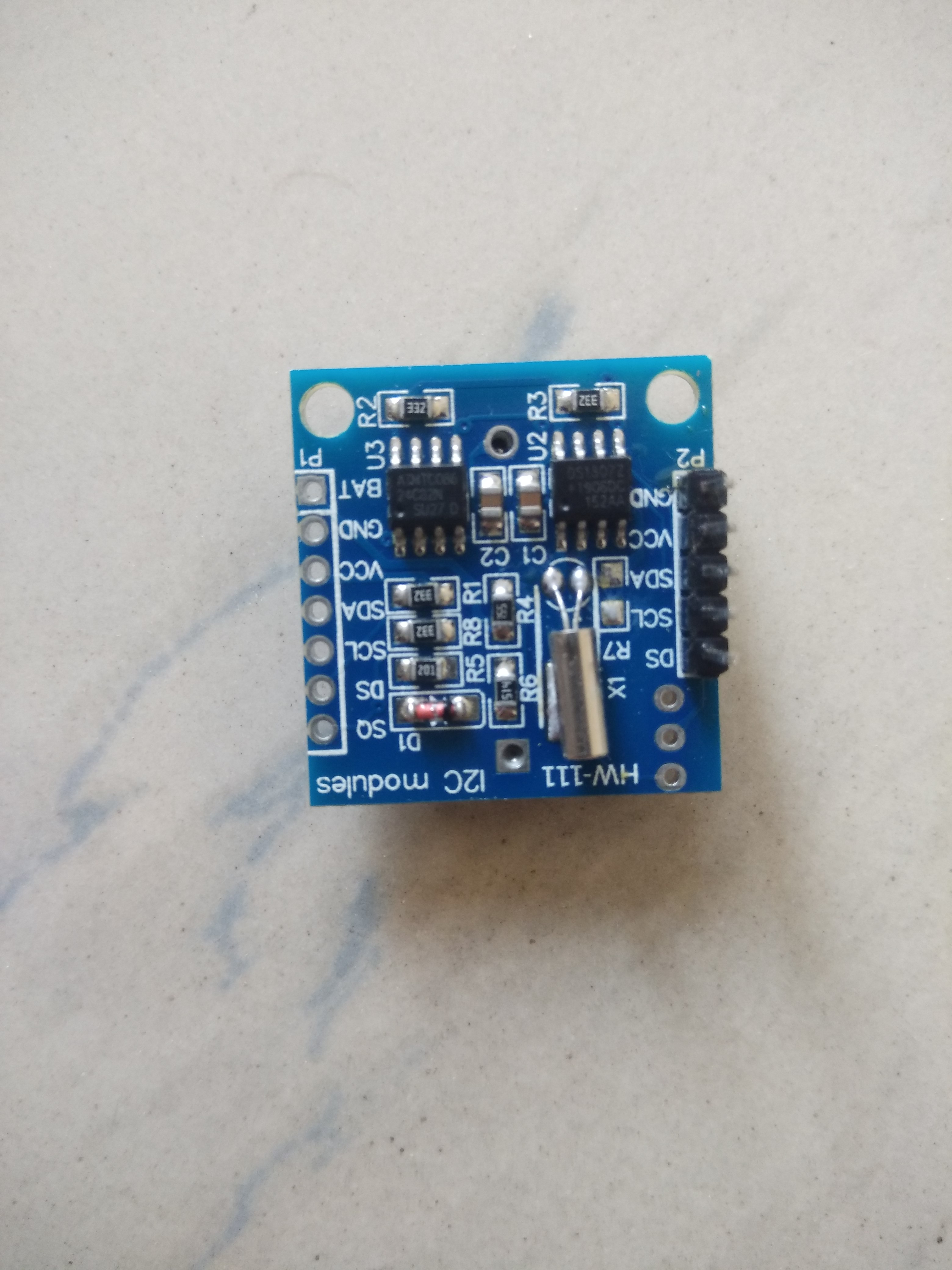
Deep Dive into DS1307 RTC Module Operation
This module operates using the DS1307 chip, a Real-Time Clock circuit capable of counting hours, minutes, seconds, day of the week, date, month, and year. It also automatically compensates for Leap Years until the year 2100.
Key features include extremely low power consumption and the ability to switch to a 3V Lithium battery backup (e.g., CR2032) when the main power supply is disconnected. This ensures that time data continues to advance without loss. The system communicates with the Arduino via the I2C (Inter-Integrated Circuit) protocol, also known as the Two-Wire Interface, which uses only two signal wires: SDA (Serial Data) and SCL (Serial Clock).
In terms of software, the DS1307 stores data in BCD (Binary Coded Decimal) format, meaning that each byte of its Register is divided into upper and lower 4-bit nibbles to represent decimal values. When we want to display these values on an LCD, we need an algorithm to convert these BCD values into decimal numbers or human-readable strings.
Displaying with the HD44780 LCD Screen
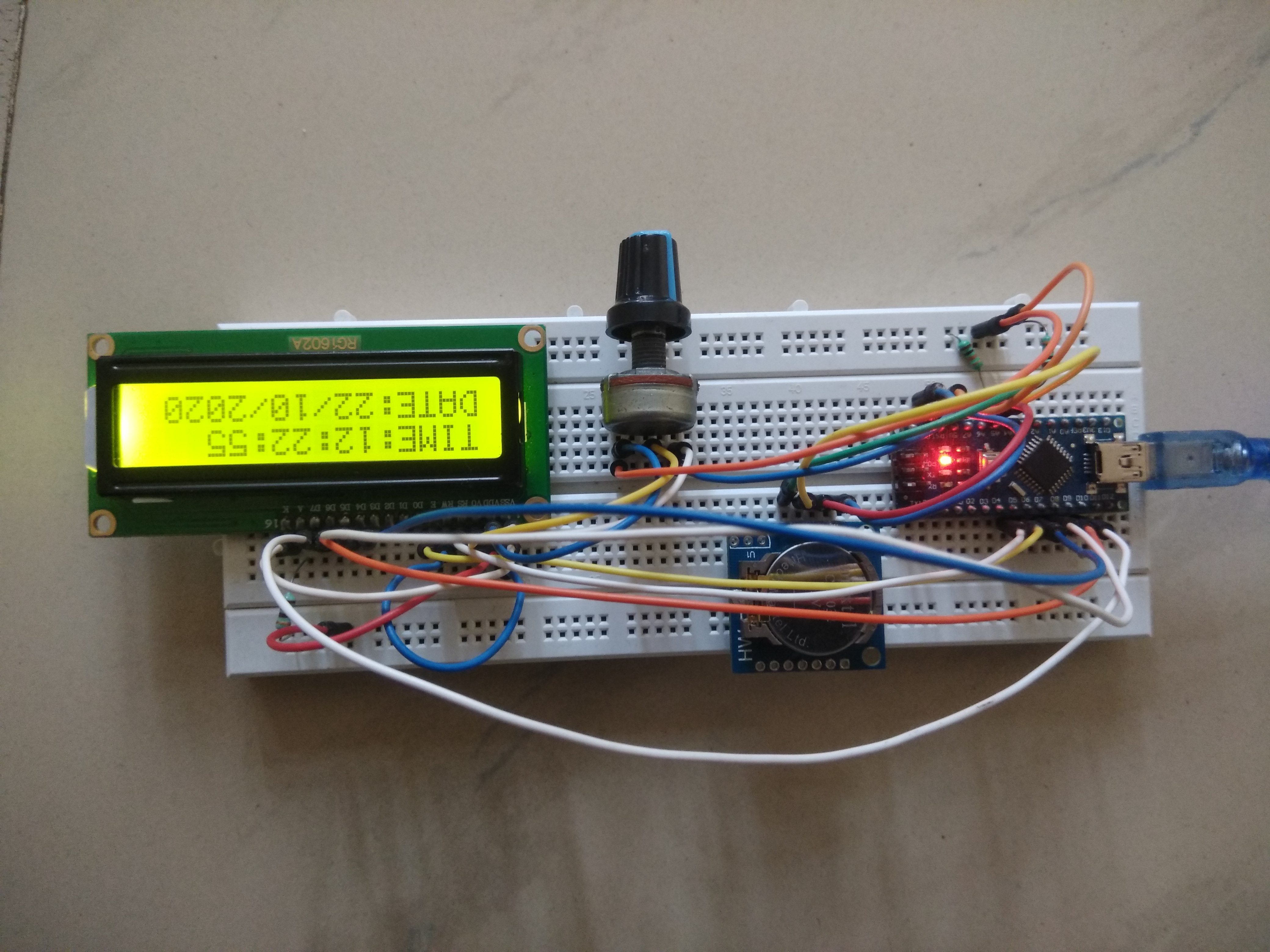
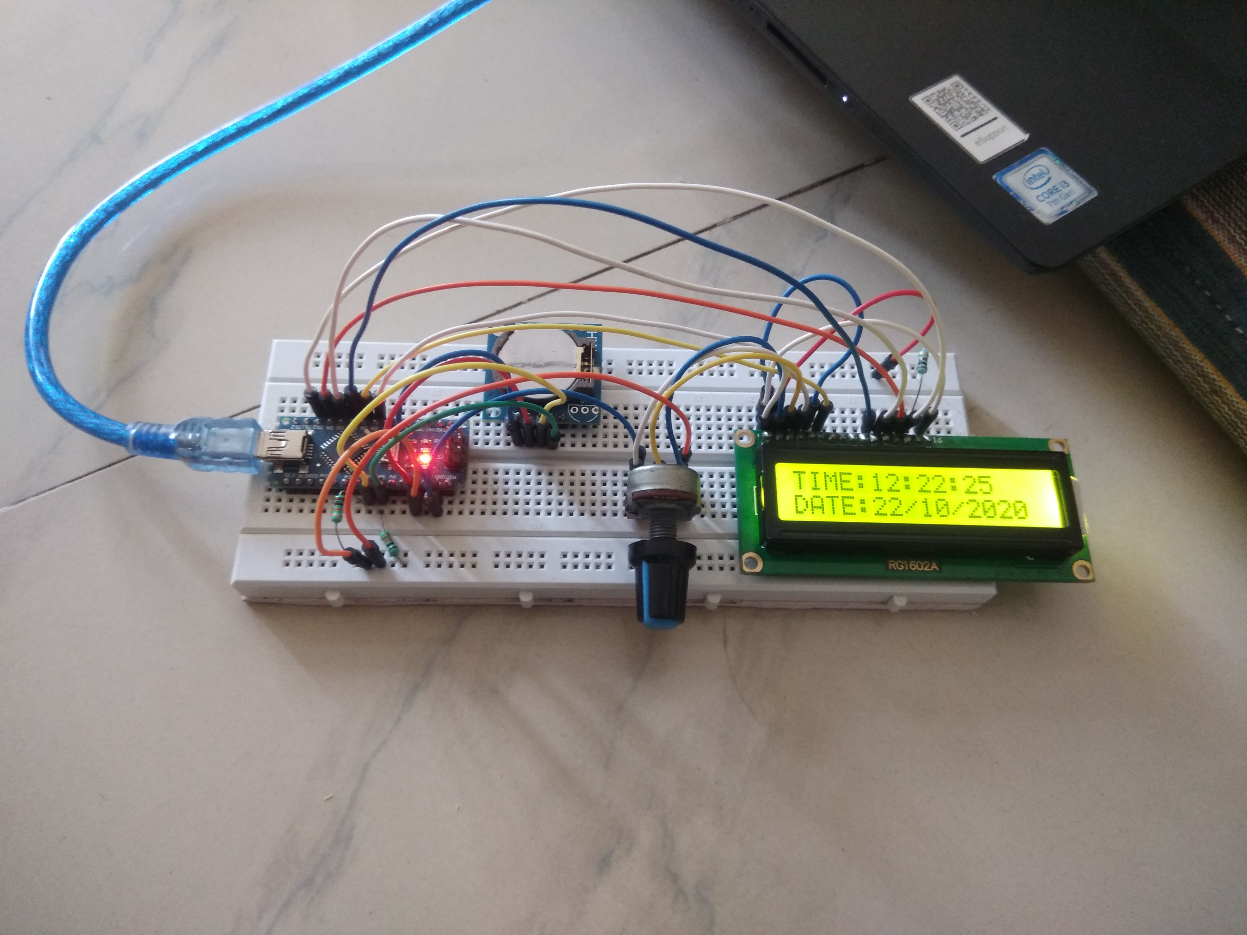
For display purposes, I chose a 16x2 LCD screen utilizing the standard HD44780 controller. This type of screen is widely used and fully supported by the LiquidCrystal library in Arduino, making programming control easier than with a 7-Segment Display. The screen receives data from the Arduino to display both time (HH:MM:SS) on the first line and date (DD/MM/YYYY) on the second line.
The Potentiometer is connected to the V0 (Contrast Pin) of the LCD to create a Voltage Divider for adjusting the character intensity on the screen, suitable for varying light conditions.
Importance of Pull-up Resistors (10K)
In an I2C bus system, connected devices typically have Open-Collector or Open-Drain outputs, meaning the device can pull the signal down to ground (Low) but cannot actively drive the signal to High by itself. Therefore, 10K Ohm Pull-up resistors are necessary, connected between the SDA/SCL lines and the VCC voltage, to pull the voltage level to a High state when no device is transmitting data. Without these resistors, the I2C communication system will not function, and the program will hang during communication with the RTC.
Control System and Configuration via Push Button
To allow users to adjust the time, I have installed Push Buttons to select the configuration mode and increment/decrement values in the DS1307's Registers. The program's logic will detect button presses (Polling) and update values to the RTC via I2C data transmission commands. When a value is changed, the new data is immediately written to the DS1307's Register, and timekeeping resumes from that new value.
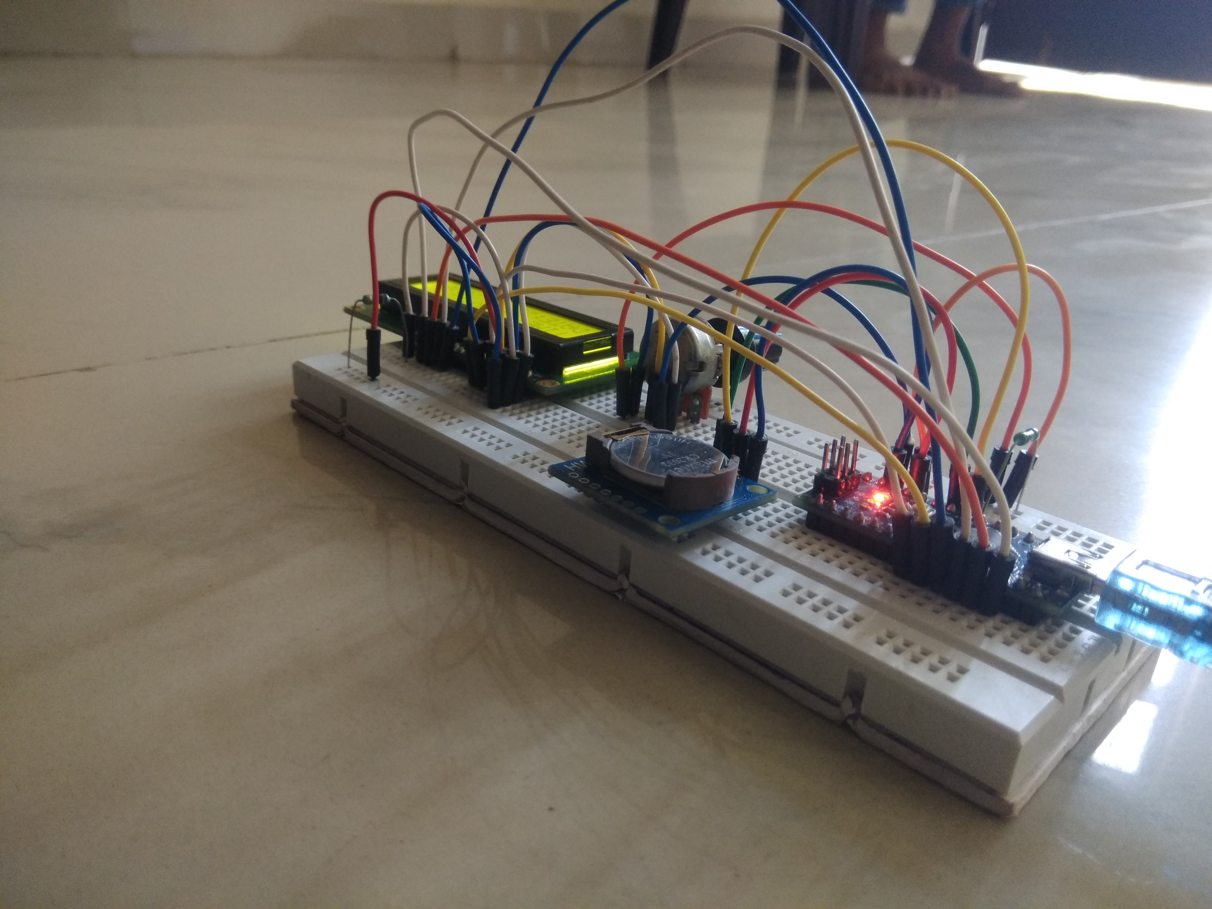
Project Success (Success!)
Once the circuit is assembled and the Code uploaded to the Arduino Nano, you will have an accurate and stable digital clock, ready for use in all situations.

Author: Ramji Patel Jhansi (INDIA)