The HPDL-1414 is a 16-segment LED display with four printable fields that is over twenty years old. It has a red GaAsP screen to which we can add the epithet "smart", because it is capable of printing alphanumeric characters on its fields.
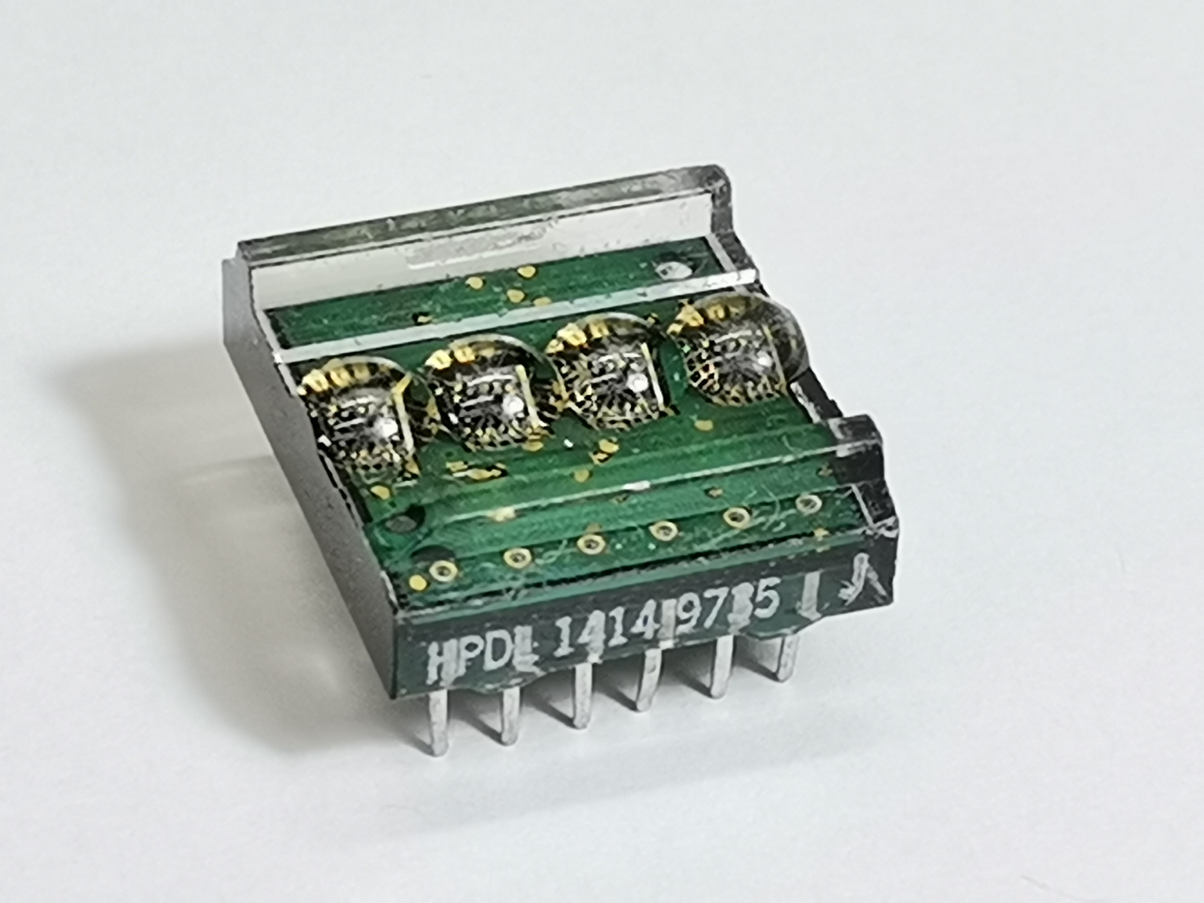
The screen is controlled by a CMOS integrated circuit embedded in a plastic housing.This circuit contains RAM, ASCI II decoder, multiplexer and LED drivers. Thanks to these features, no additional components are needed to connect this display to the microcontroller. More displays can be connected in series, where for each subsequent one it is necessary to assign another GPIO to the WR pin, similar to the SPI interface.
The Parallel Data Bus Architecture
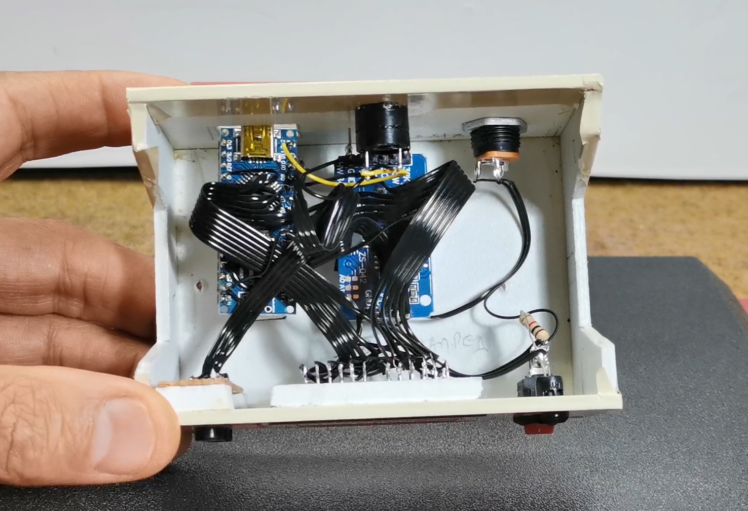
You do not use standard I2C (2 wires) for this chip. You must wire a chaotic web of jumper cables because it uses the ancient parallel data protocol.
- The HPDL1414 requires 7 Data Pins (
D0 - D6) to receive a single ASCII character (e.g.,01000001for 'A'). - It requires 2 Address Pins (
A0, A1) to tell the chip exactly which of the 4 tiny screens to print the letter on. - It requires a Write Enable Pin (
WR). - The C++ Execution: To write the letter "T" onto the first screen block:
- The Arduino slams the 7 data pins HIGH and LOW to match the binary code for 'T'.
- It sets A0 and A1 to LOW (Targeting Screen Position 0).
- It violently pulses the
WRpin LOW then HIGH. - The HPDL1414 catches the binary, shoves it into its internal 1980s memory matrix, and fires the gorgeous red segmented LEDs!
In one of my previous videos I presented you a miniature clock with these displays, as well as the way in which static and moving text can be written on it. Unfortunately at that moment I didn't manage to create a version of the code in which I could adjust the time manually with buttons, which would make this nice retro clock complete, although when making the case I incorporated three buttons for this purpose.
This time I will present you the new version of this project, where in addition to manually setting the time, I also added a Alarm function with a pulsating beep on a small Buzzer.
Cold War Era Parts Setup
The device is very simple to make and consists of several components:
- Arduino Nano (Its small chassis hides beautifully behind the massive retro displays).
- Two HPDL-1414 Displays (Sourced primarily from vintage NOS military or calculator surplus on eBay).
- DS3231 RTC Module.
- A complex mess of 20+ jumper wires manually routing the parallel data bus!
- Three Buttons
- And small active Buzzer
Interfacing the Chronometer (DS3231)
Because the massive HPDL displays consume almost every single pin on the Uno, you must build the timekeeping engine efficiently.
- A DS3231 I2C RTC is wired to
A4/A5. - The Arduino extracts the Unix time, breaks the string
10:45into individualchararrays! - It physically loops through the characters, translating each one into 7-bit parallel binary, blasting them sequentially into the retro display.
- Alarm Logic: A complex push-button menu allows the user to manually increment the alarm variables
alarmHrandalarmMin. When they match the RTC clock, an NPN transistor triggers a massive mechanical buzzer!
This project is sponsored by PCBWay. This year, PCBWay organizes the Seventh Project Design Contest where, in addition to Electronic and Mechanical Project, also has been added a new category: STM32 Project. For the best selected projects are provided rich prizes in cash, coupons and special gifts. Submit your project for participation in this Contest from 2nd, Sep, 2024 to 19th, Jan, 2025. For more details and instructions visit the given page. Let PCBway always be your first choice.

Now follows a brief description of the device's functions. Immediately after switching on, a moving demo text appears on the display, after which the set time is displayed in the form of Hours, Minutes, and Seconds. To enter the menu for setting the correct time, press the "S" button.
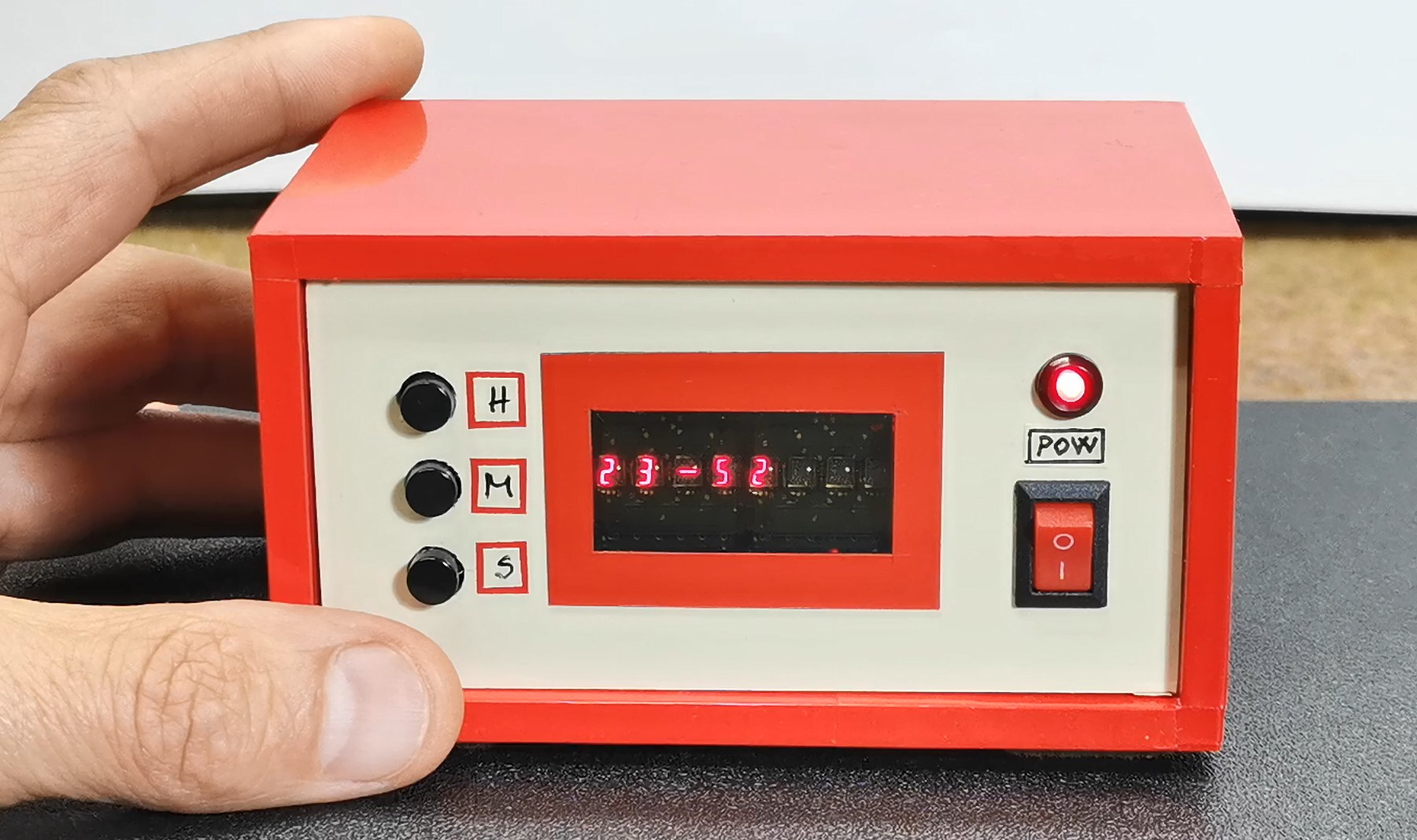
Now with the "H" button the hour is set, and with the "M" button the minutes are set. With the next click on the "S" button, we enter the menu for setting the alarm.
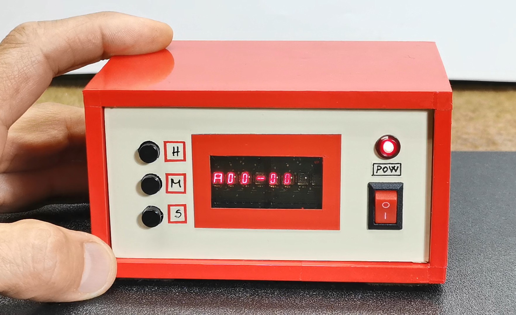
The setting principle is the same as before, only this time the letter "A" appears at the beginning, unlike the previous menu.
The alarm is activated at the set time in the form of short beeps with a duration of 500mS, and is deactivated simply by pressing the set button.
And finally a short conclusion. This is a small, simple, but really interesting unusual clock that shows the time on retro displays made by Hewlett-Packard at the turn of the last century, and was also used for calculators and measuring instruments.