When I was a child, I used to love LEGO trains. I used to build my own and control them with LEGO's Power Functions. However, as I grew older, I wanted to control my trains with my own circuitry. I started working on a prototype for a wirelessly controlled train that could be controlled through Bluetooth LE. However, after I completed the prototype, I tested it out and saw it was not working reliably through BLE. Later, I started working with the Arduino IoT Cloud and thought, "why can't I use this to control a train." I immediately revised my prototype to be controlled using Arduino's IoT Cloud. When I tested it out, it worked flawlessly. The IoT Cloud also let me add LED Channels into the train and control them via switches rather than numbers. (BLE does not have any boolean switches)
Notes:
- with the breadboard, you will need to remove the ground and power rails on either side of the breadboard by cutting through the adhesive layer on the bottom and sliding them off of the center breadboard (Image Below)
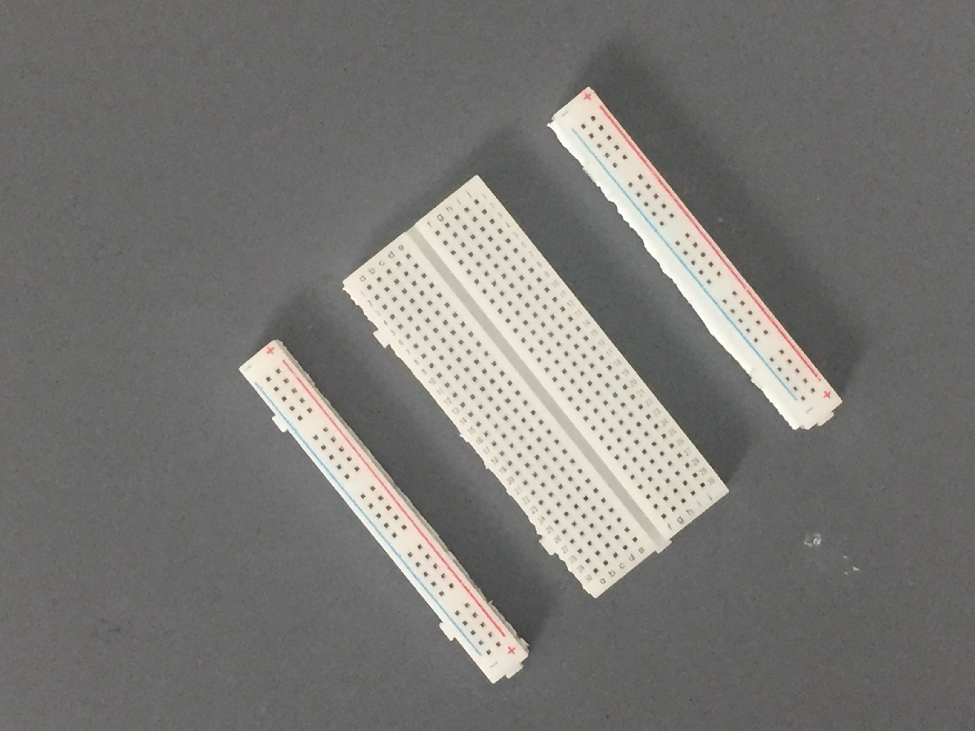
- In the actual project, I used breadboard jumper wires like the ones in the picture below to achieve a compact fit, but you can use normal jumper wires to wire the circuit like the ones I will use to demonstrate the wiring
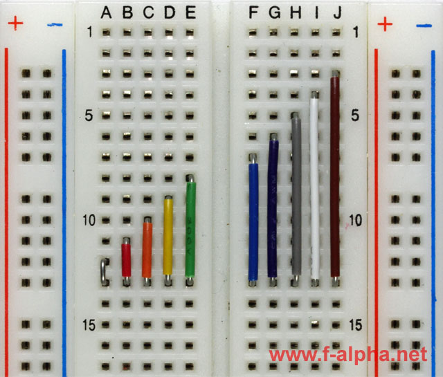 Image: www.f-alpha.net
- If the 9V battery clips you are using do not have breadboard headers (like mine), you may need to solder some headers or jumper wires like the ones above to achieve a secure fit.
- Link to Arduino's Getting Started guide for Arduino IoT Cloud if you need: https://docs.arduino.cc/cloud/iot-cloud/tutorials/iot-cloud-getting-started
Building Sequence:
- Attach an L293D motor driver on one end of the breadboard and connect the GND pins on either side to each other using jumper wires (attach L293D pins 4 and 5 together and pins 12 and 13 together)
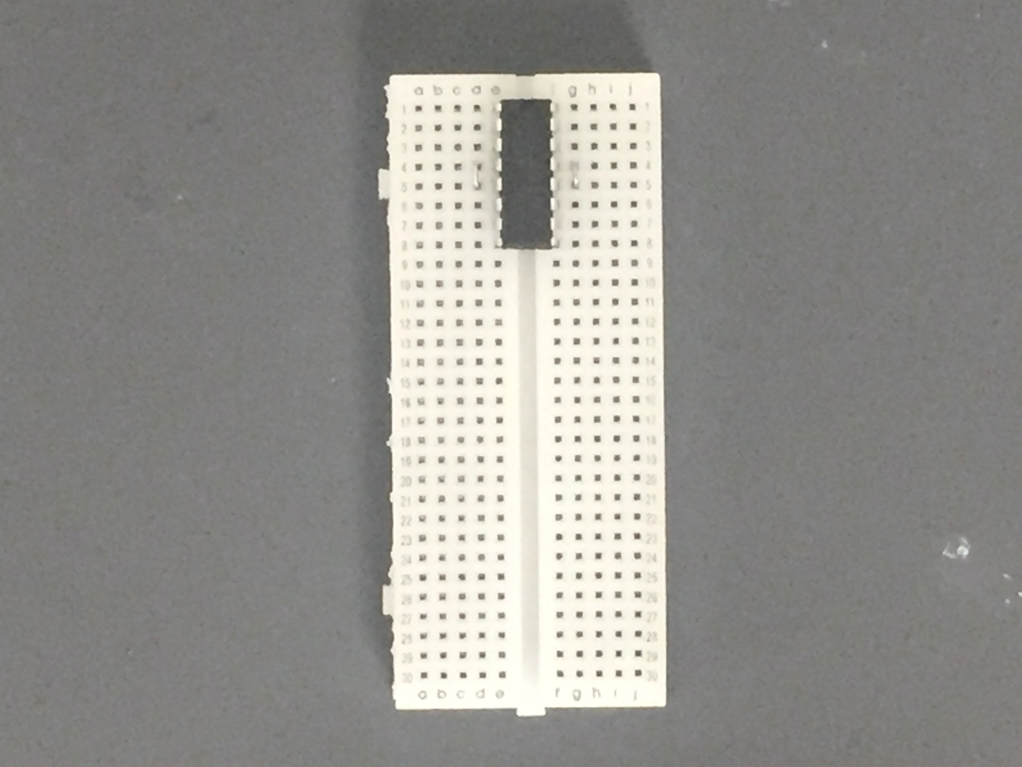 L293D motor driver
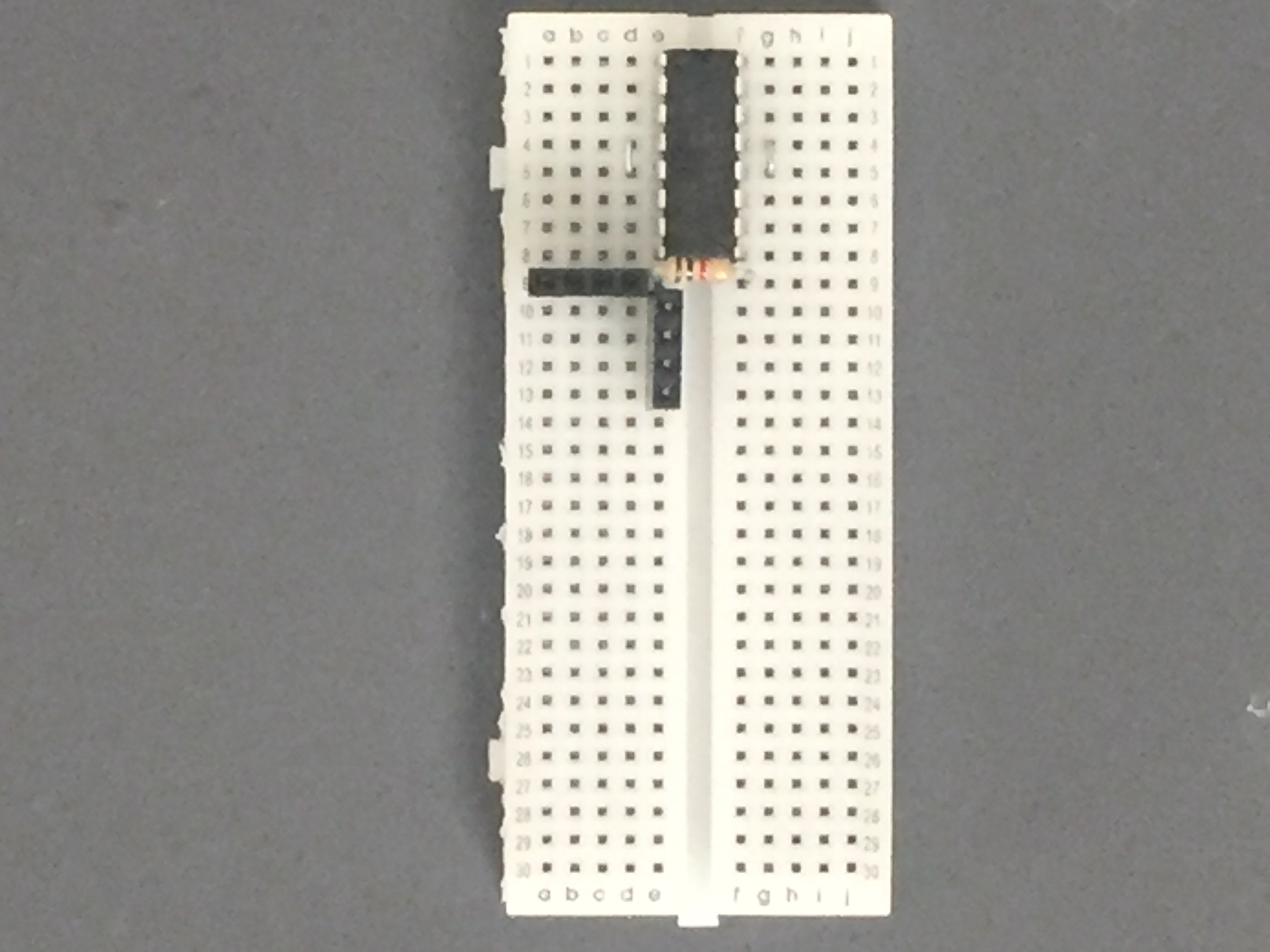
OPTIONAL STEP: attach headers to your breadboard for a clean look and easy to wire the LEDs to the breadboard since wiring can get tough later in the project. You do not need these headers though; you can simply put wires where the headers are and connect LEDs to those wires later. (Picture on step 3)
Attach a 1k ohm resistor to the breadboard where the LED's ground wires (or headers) will be attached
 Headers are optional! you can put jumper wires to attach your LEDs where the headers are
Attach the Nano 33 IoT Board to the breadboard (it will be a congested fit). make sure the micro USB is facing outwards since it won't be programmable otherwise (Picture on step 5)
Attach wires to the GND pin and digital pins 2, 3, 5, and 6 (LEDs require PWM pins for brightness modulation). Connect these wires to the breadboard row where the header pins are and the GND wire to the 1k ohm resistor. Each LED is on a separate channel that can be controlled individually. For the purpose of this project, however, everything is controlled by the same IoT Variable

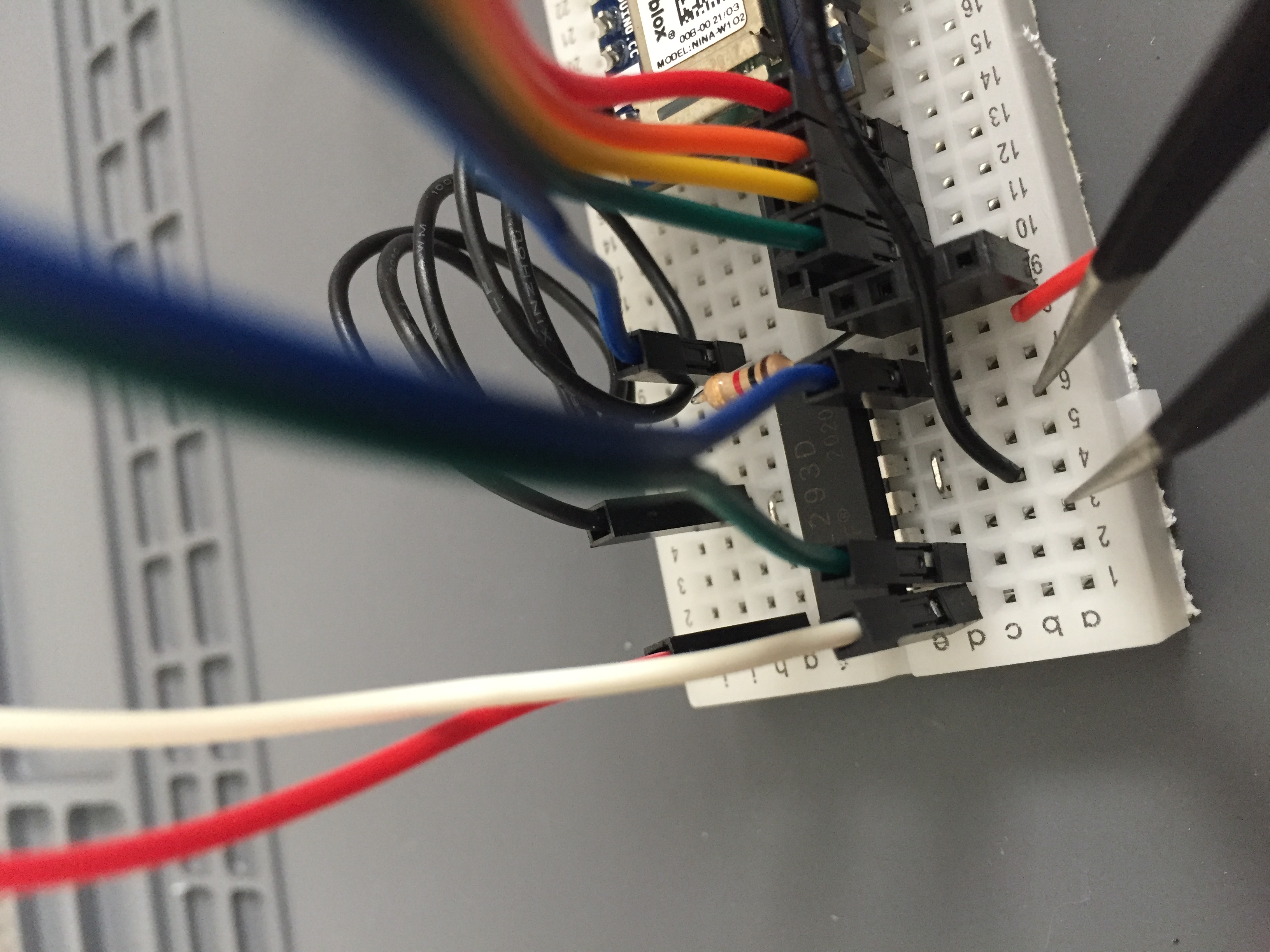
- (Wires that connect to LEDs are removed only for instructional purposes. You do not need to remove them on this step) Attach wires to digital Pins 10, 11, and 12. Connect digital pins 10 and 11 to pins 2 and 7 on the L293D motor driver (the side that has a crevice on the top is pins 1-8). Attach digital pin 12 to pin 1 on the L293D. This will control the speed of the motor. Then, attach pin 16 on the L293D to the 3.3V pin on the Nano 33 IoT and GND pins to the 2nd GND on the Nano 33 IoT (having the two pins together like instructed on the first step makes the process of grounding much easier. Batteries will also be connected, which can be tough when there are two GND pins it needs to connect to)
 Wires that connect to LEDs are removed only for instructional purposes. You do not need to remove them on this step
- Next, attach battery clips in the following positions: one battery clip must connect to pin 8 on the L293D for power and pin 3 or 4 on the L293D for grounding. The other battery clip must connect to VIN (Voltage In) pin on Nano 33 IoT and GND pin on Nano 33 IoT. DO NOT CONNECT BATTERIES YET

- Attach your motor to pins 3 and 6 on the L293D (tweezers show the pins)
EXPANDED TECHNICAL DETAILS: Direct Track PWM Actuation (L293D/L298N)
An Arduino cannot power a massive metal locomotive; it requires serious industrial voltage. In this project, we use a 9V battery for the motor driver, but the principle scales up. The core concept is Direct Track PWM Actuation:
The high-voltage DC power source (like a 12V or 18V DC Power Supply for larger trains) is routed directly into a motor driver like the L293D or an L298N Motor Driver Module.
Instead of outputting to a tiny robot wheel, the driver's output terminals are physically wired straight to the train's motor or the steel train rails in a track-powered setup!
The Arduino Nano 33 IoT acts as the brain. It commands the motor driver using pure mathematical
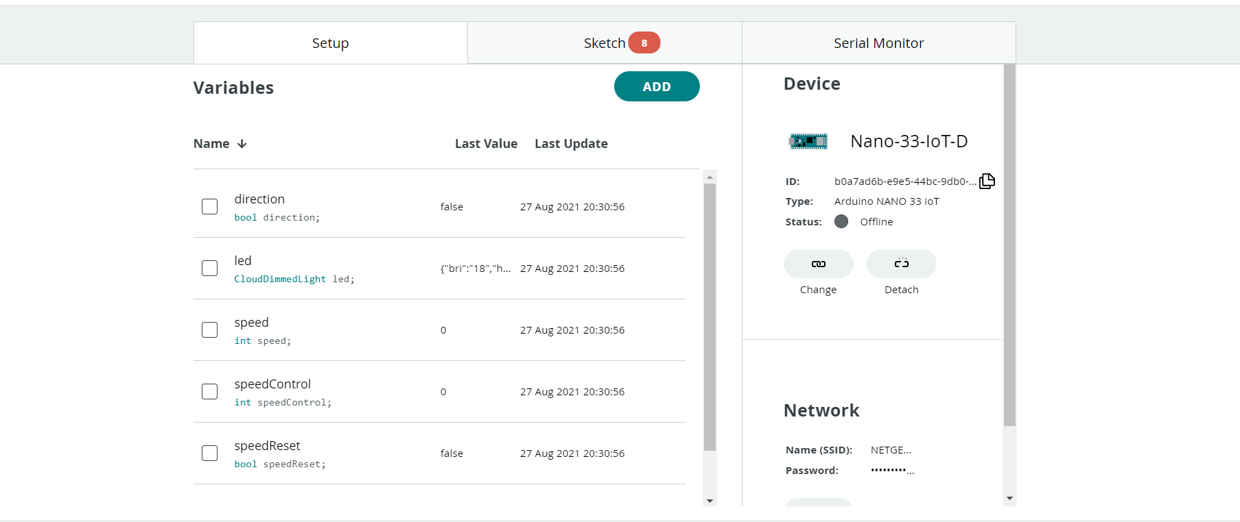
analogWrite(enablePin, speed)PWM (Pulse Width Modulation) manipulation. By rapidly pulsing the high-voltage electricity, it achieves buttery-smooth slow-speed crawling that a simple analog transformer could never replicate!Connect a cable to your Nano 33 IoT and create a Thing with the following variables and classes: Class Variable
- bool direction
- CloudDimmedLight led
- int speed
- int speedControl
- bool speedReset
Set up your Nano 33 IoT as your board for this project and enter your network credentials in the field below it
Open your Thing's sketch in the Sketch tab and copy the code featured below (Comments are featured in the code to explain how it functions). Then, upload it to your Nano 33 IoT
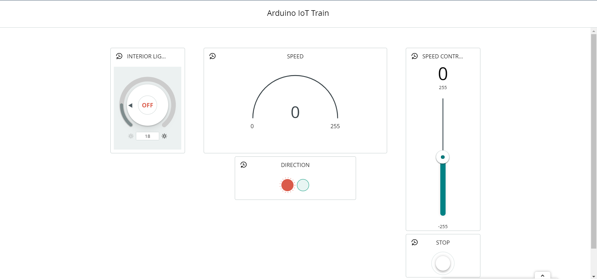
Go to the dashboard tab in IoT Cloud and create a dashboard. Next, create widgets (the things in the picture below that control the variables) and link them to each variable. You do not need to have the same widgets as mine, but I think this is the easiest and most straightforward design. Reload the page, and you should have a working motor and LEDs If you do not, try re-linking to each variable Here is a list of how to link to each variable
- INTERIOR LIGHT Widget ==> led
- SPEED Widget ==> speed
- SPEED CONTROL Widget==> speedControl
- STOP Widget ==> speedReset
- DIRECTION Widget ==> direction
EXPANDED TECHNICAL DETAILS: The Web Server Interface (via Arduino IoT Cloud)
The Arduino Nano 33 IoT connects to your home Wi-Fi router and communicates with the Arduino IoT Cloud.
- The IoT Cloud acts as a sophisticated intermediary web server. You create a graphical dashboard in the cloud containing sliders, switches, and buttons.
- You open this dashboard on any device—a phone, tablet, or computer. Dragging a slider or pressing a button instantly sends a command through the cloud to your specific board.
- The Nano 33 IoT receives this command, maps the value to a PWM or digital output, and the train immediately responds.
- This cloud-based approach provides a robust, secure, and user-friendly interface without needing to write low-level web server code, making it perfect for complex multi-variable control like this train project.
Congratulations, you have completed this project! You can now remove the cable connecting your computer to the board, and plug the batteries into the clips. The Nano 33 IoT should now work wirelessly by connecting to your internet and communicating with the IoT Cloud. If you have any questions, problems, or advice, please comment below and I will get back to you as soon as possible.
A demonstration of this project is below.
Thanks for reading!