Arduino IR remote
Transform your TV remote into a smart light controller with Arduino and a TSOP1738 sensor
In this project, I will guide everyone to transform a common TV remote lying around your home into a wireless RGB LED light color control device via infrared (IR Remote Control), using an Arduino board as the main processor. This serves as a fundamental step in learning about Home Automation systems and wireless data communication.
Hardware List
To successfully complete this project, you will need to prepare the following equipment:
- Microcontroller Board: You can choose from various models such as Arduino Uno, Nano, Mega, Pro Mini, or Pro Micro, depending on the installation space.
- TSOP1738 Infrared Receiver Sensor: The key component that will receive and decode signals from the remote.
- RGB LED: For displaying various colors (Common Cathode or Common Anode recommended, depending on what you have).
- Remote Control: Any standard TV remote or IR remote you have.
- Accessories: Breadboard for circuit assembly, and Jumper Wires.
Engineering Insight
- TSOP1738 IR Sensor: This sensor is not just a regular Photo Transistor; it is a receiver that integrates a frequency filter and an amplifier circuit. It detects infrared signals transmitted at a frequency of 38 kHz (which is standard for most TV remotes). The received signal is then demodulated from its carrier wave, leaving only digital data (Logic 0 and 1) to be sent to the Arduino board.
- RGB LED & PWM Logic: The ability to achieve a wide range of colors comes from employing PWM (Pulse Width Modulation). The Arduino sends digital signals with a constant frequency but varying power delivery durations (Duty Cycle) to the Red, Green, and Blue pins of the LED to mix colors according to the principles of light (Additive Color Mixing).
Step-by-Step Guide
Step 1: Decoding the Remote
First, we need to know what "secret codes" (Hexadecimal Codes) the remote sends when each button is pressed.
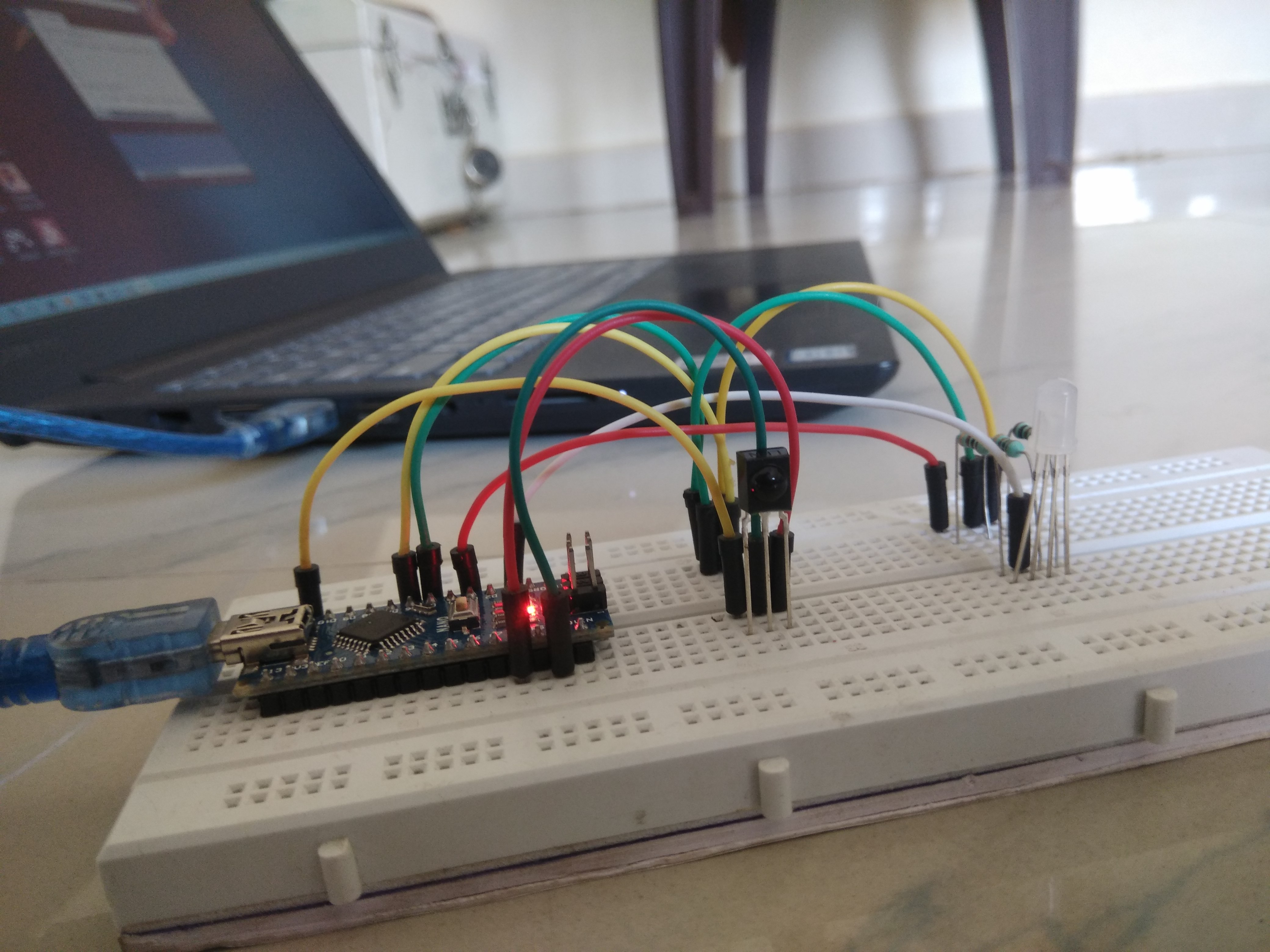
- Connect the TSOP1738 sensor circuit to the Arduino (VCC, GND, and Signal pins).
- Upload the first part of the code (IR Receiver Sketch) to prepare for reading values.
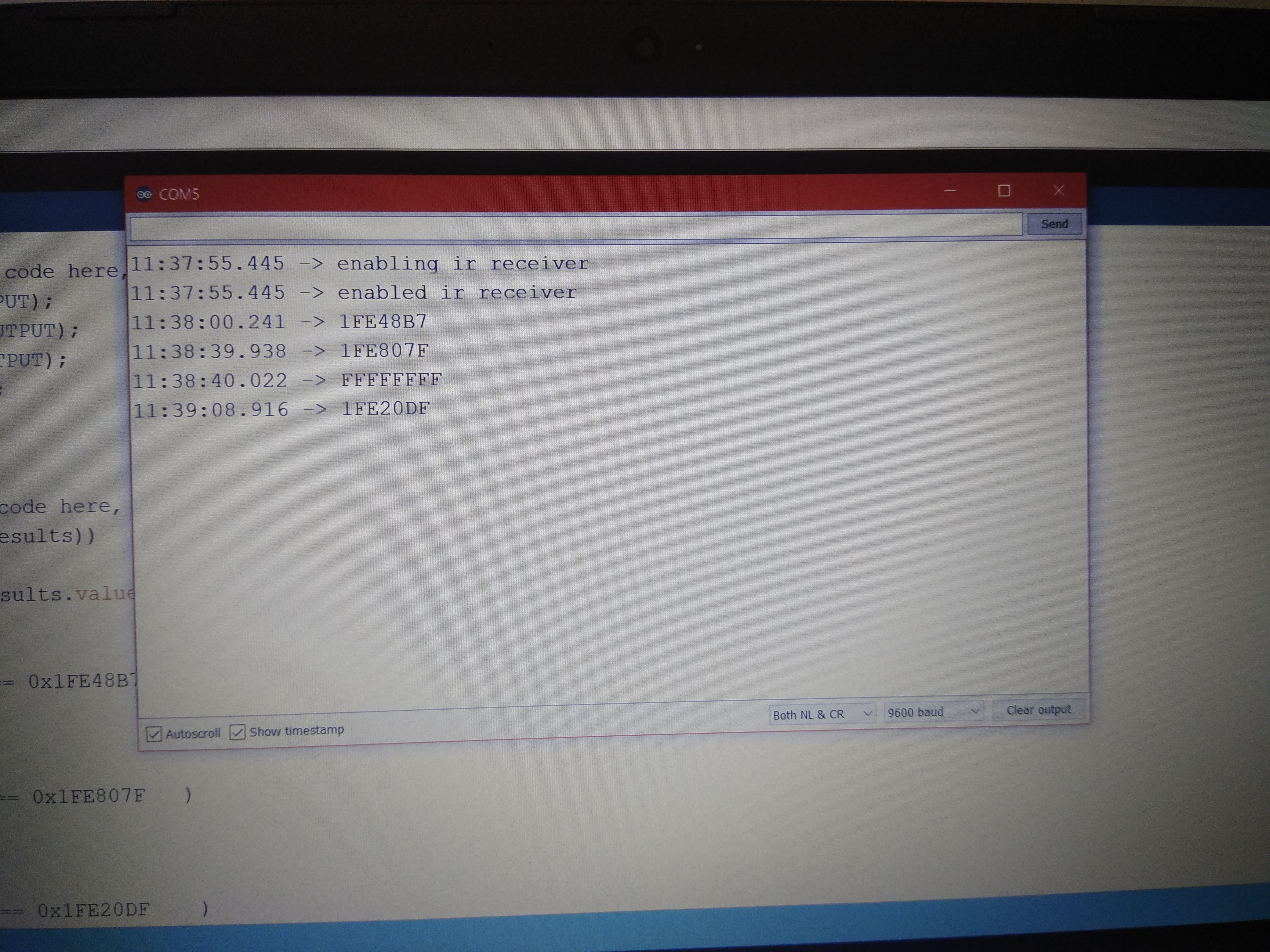
- Open the Serial Monitor in the Arduino IDE.
- Point the remote at the sensor and try pressing your desired buttons (e.g., buttons 1, 2, 3).
- You will see hexadecimal codes (Hex Codes) appear on the screen, such as
0xFF30CF. Make sure to record these codes carefully, as button codes vary between different remote brands.
Step 2: Implementing the Action
Once you have the button codes, the next step is to define "which code corresponds to which color."
- Replace the example codes in the second part of the code with the Hex codes you recorded.
- Write
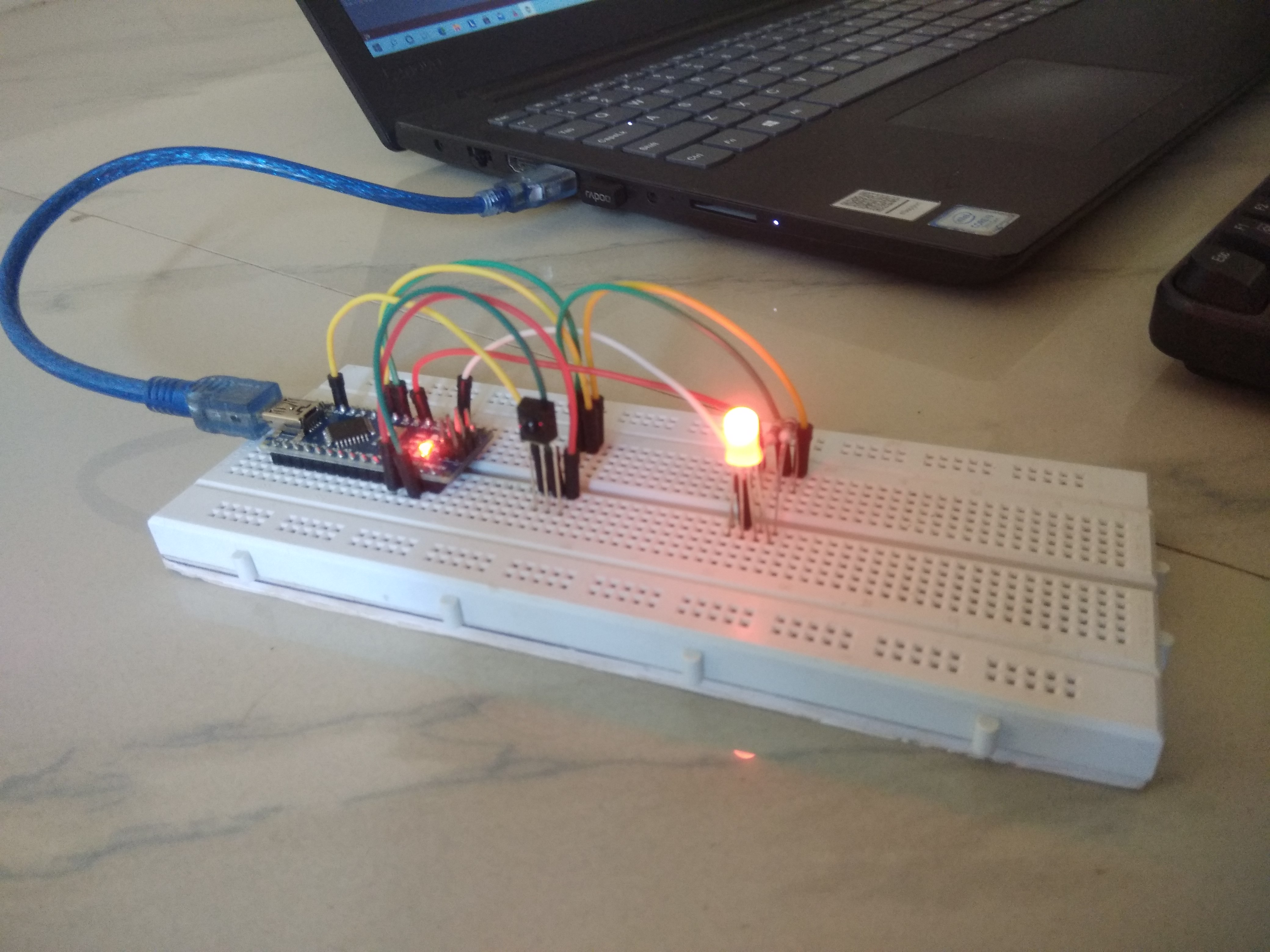
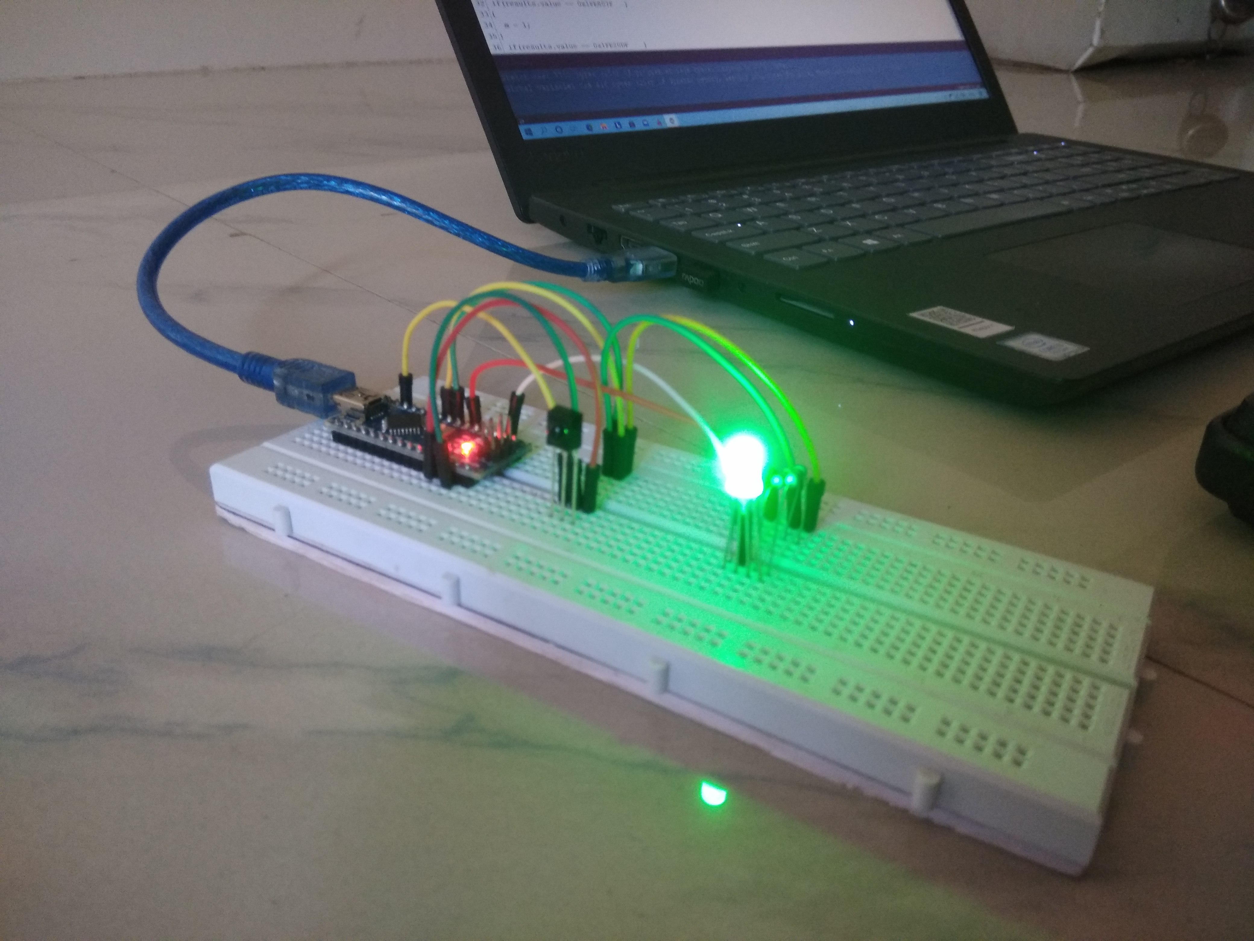
switch-caseorif-elsestatements to check which button corresponds to the value received fromirrecv.decode(&results). - Upload the code to the board and test the color changes immediately!
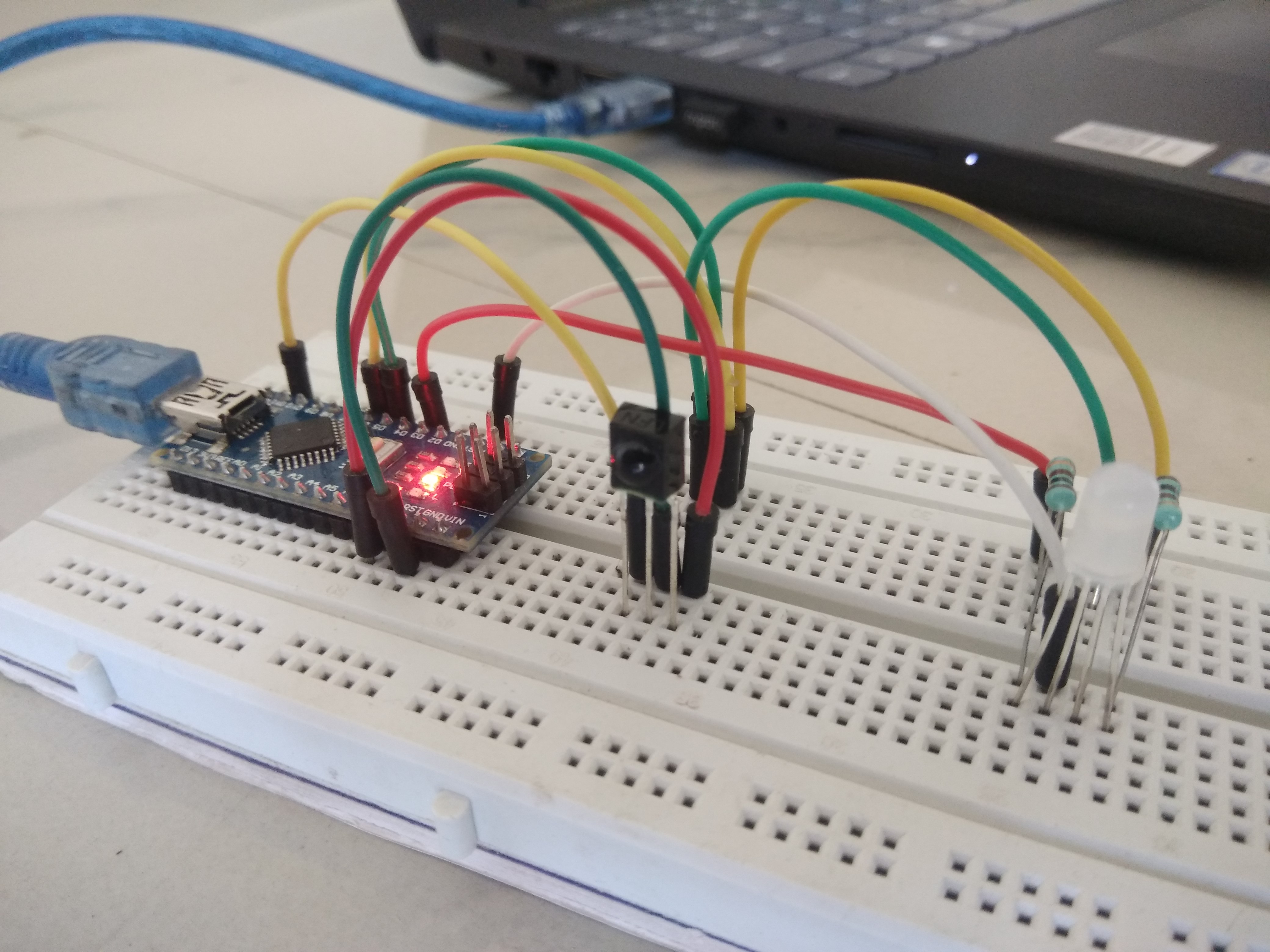
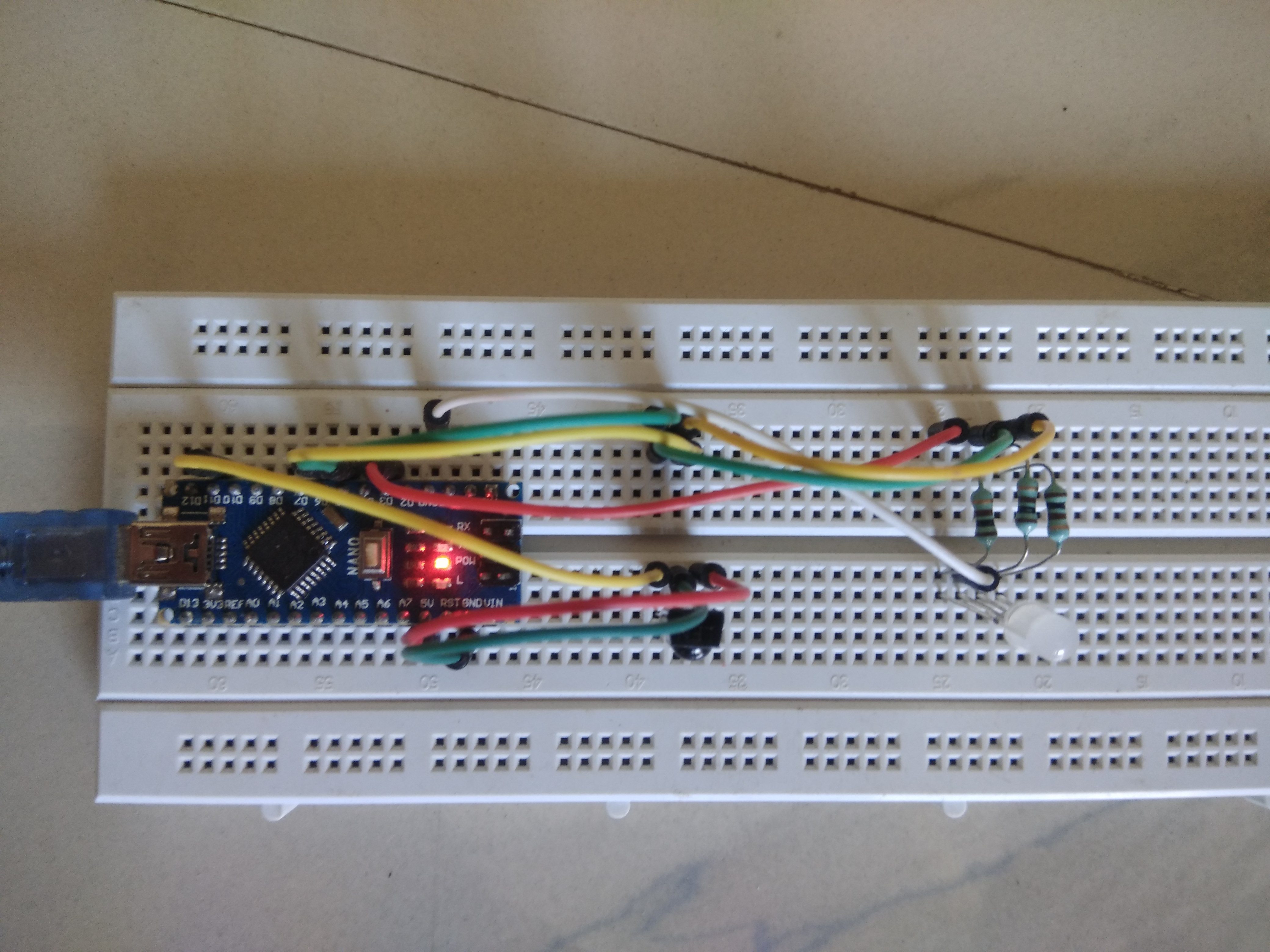
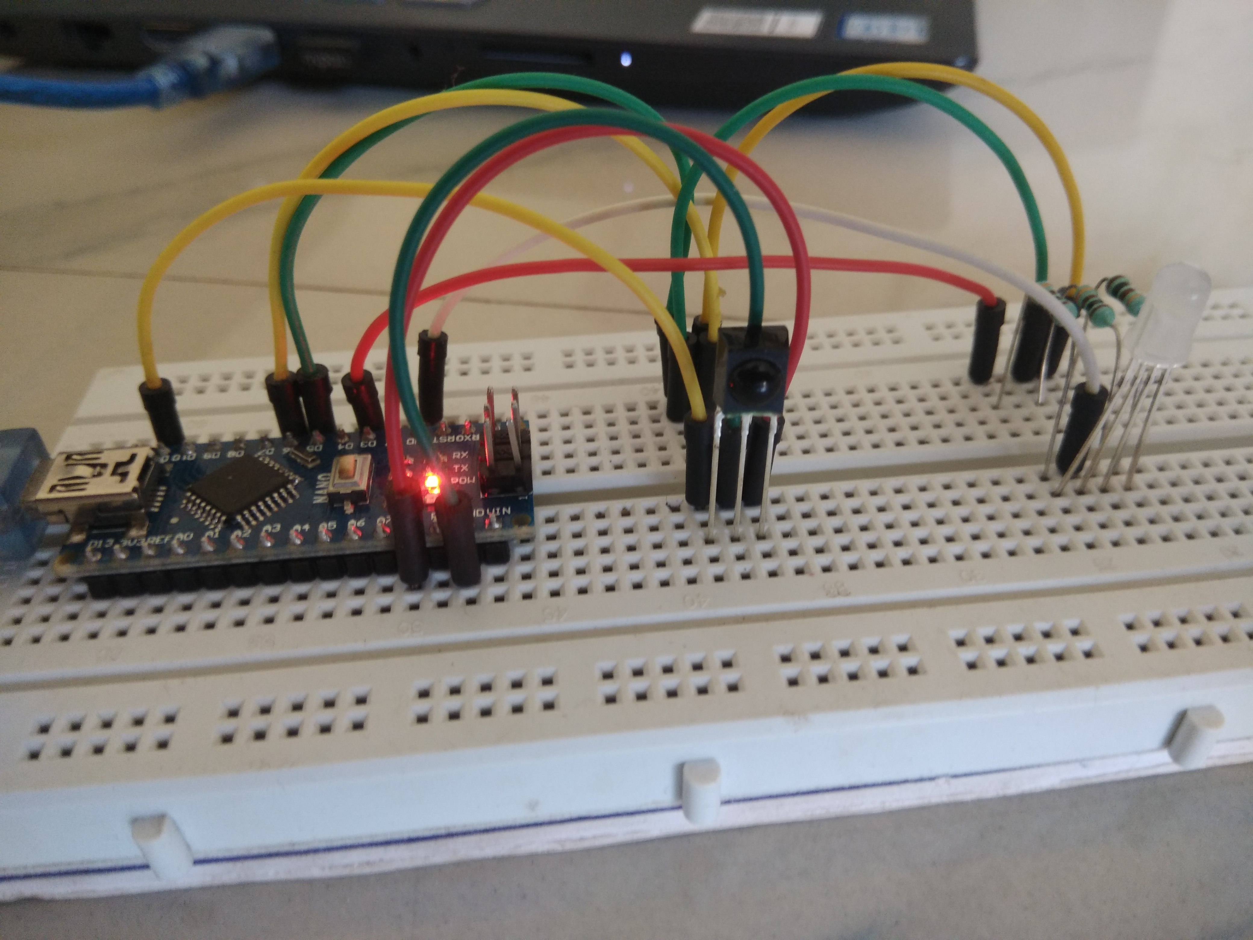
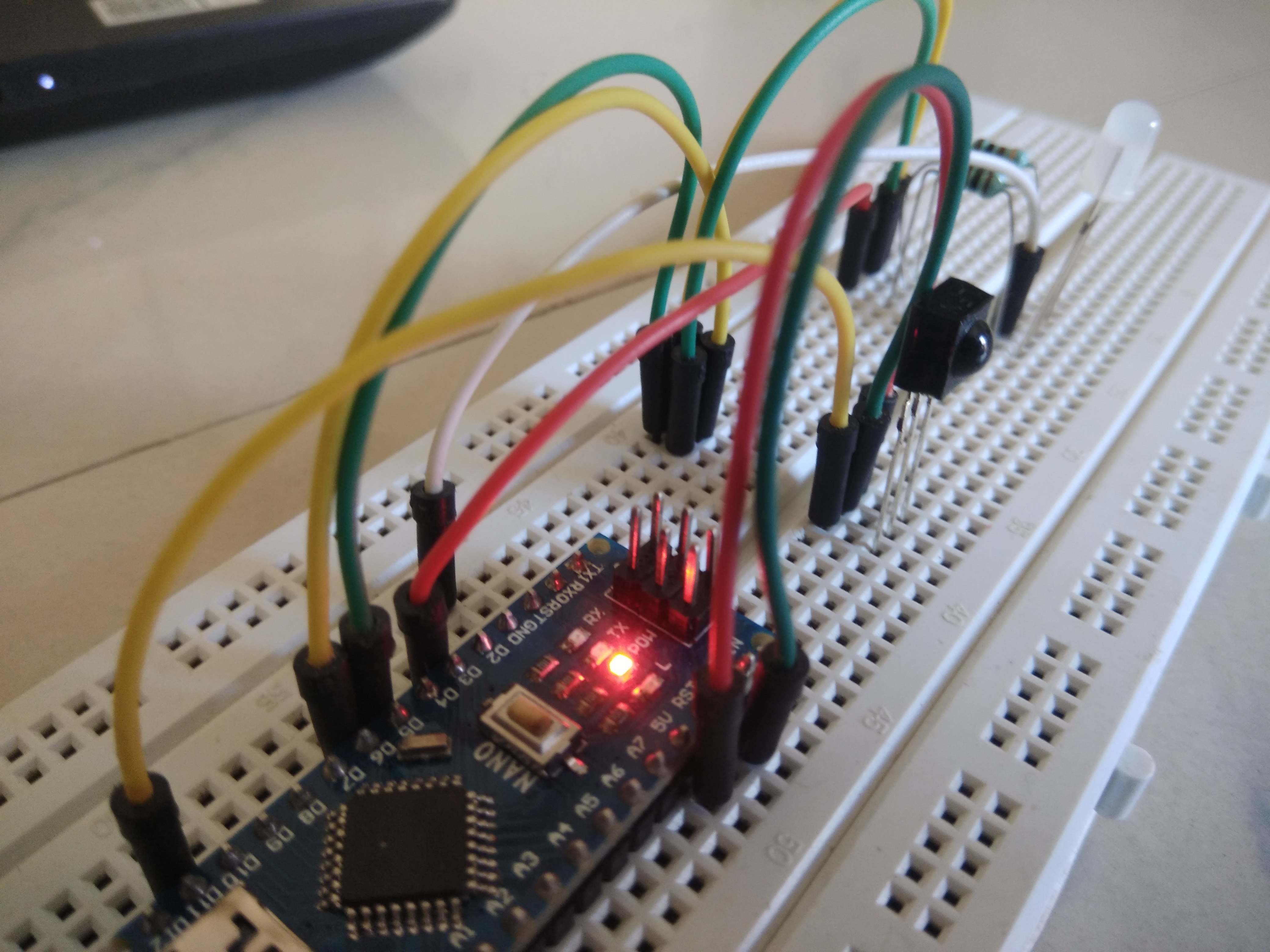
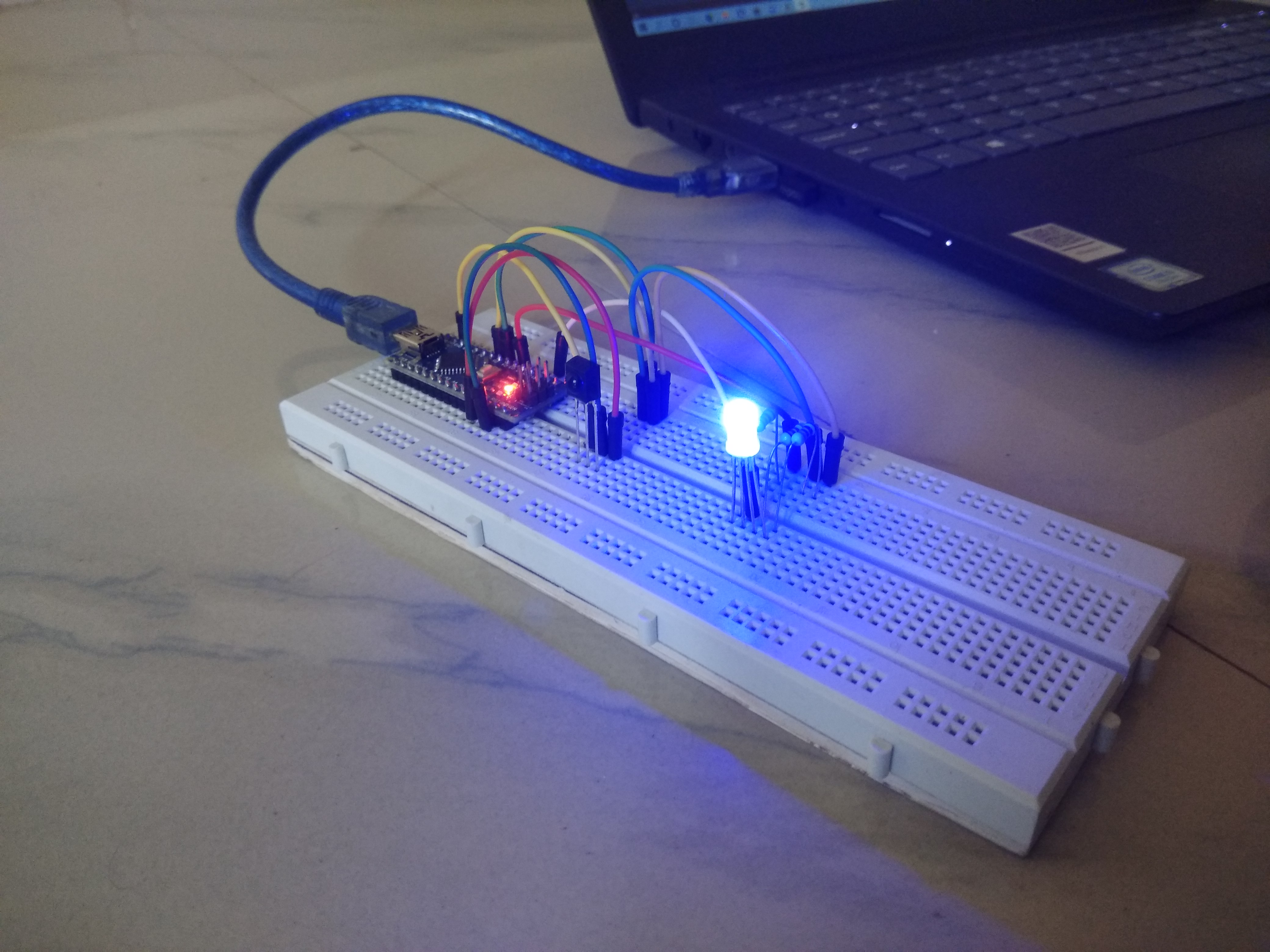
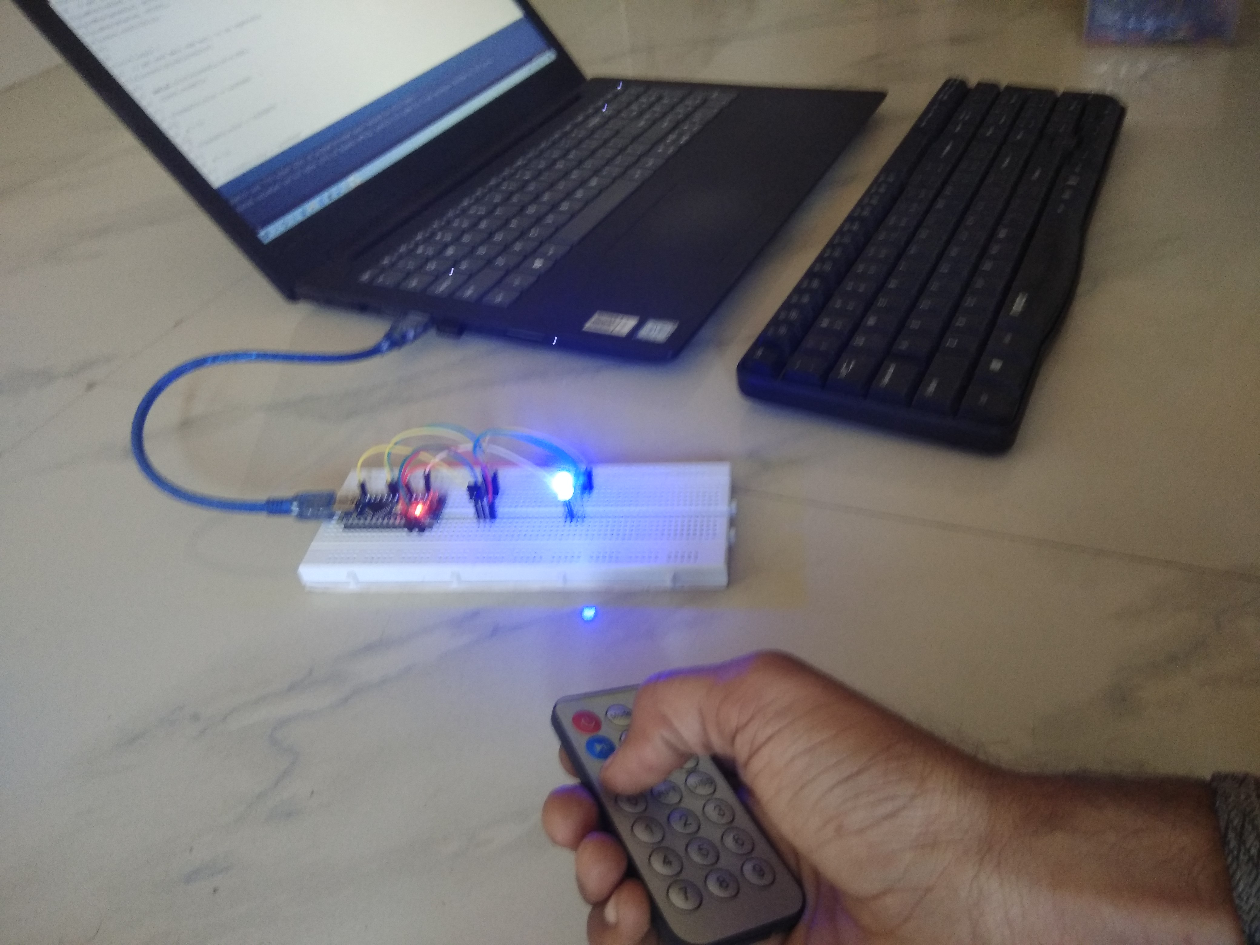
Project Photos

Required Library Installation
This project relies on the capabilities of the #include <IRremote.h> library, which is the most stable standard library for IR signal management.
- Installation Guide: Go to
Sketch->Include Library->Manage Libraries..., then search for IRremote and click Install. Alternatively, you can download it directly from GitHub.
Program Logic Analysis
In terms of programming, we will use the following main commands:
irrecv.enableIRIn();: Initializes the IR receiver.irrecv.decode(&results);: Checks if a signal has been received and decodes it, storing the result in theresults.valuevariable.analogWrite(pin, value);: Commands a PWM pin to set the brightness level for each color (values 0-255).
This project not only provides enjoyment but can also be applied to turn on/off lights in your home or control fan speeds using your existing remote. Have fun creating new innovations!
Author: Ramji Patel Jhansi (INDIA) Technical Expansion by: Embedded Systems Engineer / Technical Writer