Meet the Circle Electronic NOOB Series Knight Rider!
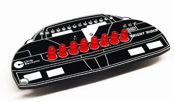
We all remember the technological car in the iconic television series Knight Rider. The most important feature of this car is that the LEDs on front of the car are constantly turn on one by one.

For those who are new in Arduino and want to learn coding, it's time to learn how to make this animation!
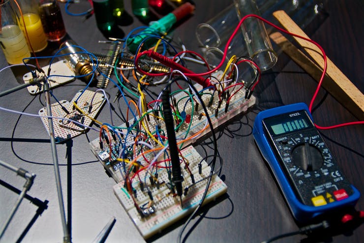
Don't mess with breadboard circuits for learning Arduino and coding, just connect the cables and start coding right now!
Project Backstory
The Arduino Knight Rider scanner is a classic beginner project that pays homage to the 1980s TV series starring K.I.T.T., the sentient car. The hallmark feature of K.I.T.T. was a red scanning light horizontally moving across the front grill.
What can you do?
- You can connect each of the 8 separate leds to the Arduino pin and make each one turn on, in turn, using the for loop.
Hardware Implementation
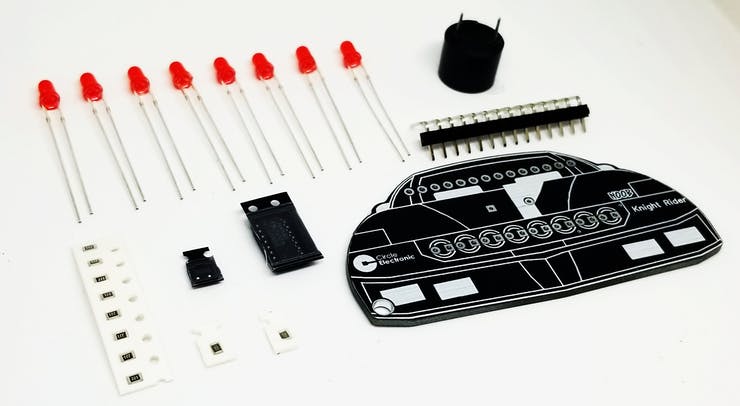
- LED Display: In this version, we use 8 or 10 red LEDs arranged in a line. Each LED cathode is connected to ground, while each anode is connected to a dedicated Arduino digital pin (e.g., Pins 2 through 11).
- Protection: Each LED required a 220-ohm resistor in series to protect the Arduino's output pins and the LEDs from excess current (V=IR).
- Thanks to the buzzer on top, you can play Knight Rider theme song and learn how to make melodies using the buzzer.
- You can learn how to program 74HC593 Led driver IC. This integrated allows you to use 8 leds with only 3 connections. You can use this IC in other projects to use the motor or anything instead of using a led.
Coding the Scanner Effect
This project is an excellent way to learn about for loops and arrays. Instead of manually turning each pin on and off, we can use a loop to iterate through the pin numbers:
// Moving Forward
for (int i = 2; i <= 11; i++) {
  digitalWrite(i, HIGH);
  delay(100);
  digitalWrite(i, LOW);
}
// Moving Backward
for (int i = 11; i >= 2; i--) {
  digitalWrite(i, HIGH);
  delay(100);
  digitalWrite(i, LOW);
}
Visual Enhancements: Persistence of Vision
To make the scanner look even more like the original K.I.T.T., you can use PWM (Pulse Width Modulation) to add a "trail" effect. As the primary LED turns off, the previous LED can slowly fade out instead of turning off instantly, creating a smoother, more liquid-like motion.
Applications
Beyond cars, this scanning effect is commonly used in:
- Status Indicators: To show that a system is currently processing or searching.
- Costume Props: Adding a futuristic look to sci-fi helmets or gear.
- Mood Lighting: A simple, eye-catching animation for display cases.
Buy knight rider now and start learning coding now!
For more details, please do not forget to visit our website and watch our YouTube video!
Code
8 LED configuration
int leds[] = {2,3,4,5,6,7,8,9};
void setup()
{
for(int i=0; i<8; i++) {
pinMode(leds[i], OUTPUT);
}
}
void loop()
{
for(int i=0; i<7; i++) {
digitalWrite(leds[i], HIGH);
delay(100);
digitalWrite(leds[i], LOW);
}
for(int j=7; j>0; j--) {
digitalWrite(leds[j], HIGH);
delay(100);
digitalWrite(leds[j], LOW);
}
}
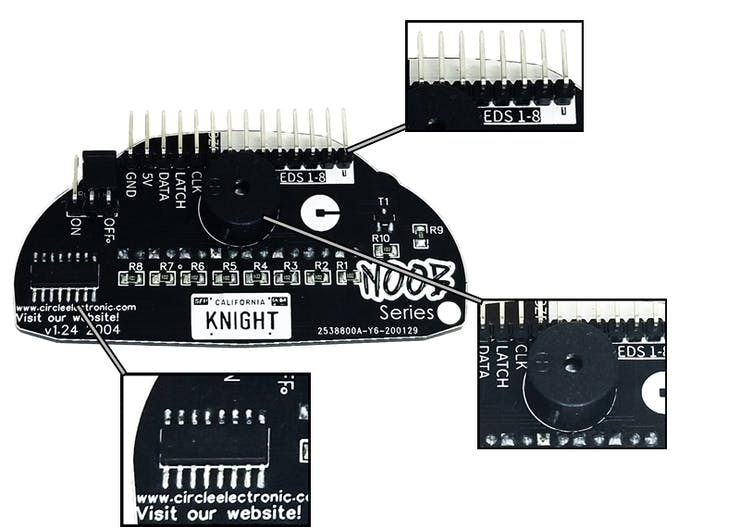
74HC595 shift register configuration
#define LATCH 9
#define CLOCK 10
#define DATA 8
static int led = 0;
byte number[23] = {0b00000000,
0b00000001,
0b00000011,
0b00000111,
0b00001110,
0b00011100,
0b00111000,
0b01110000,
0b11100000,
0b11000000,
0b10000000,
0b00000000,
0b10000000,
0b11000000,
0b11100000,
0b01110000,
0b00111000,
0b00011100,
0b00001110,
0b00000111,
0b00000011,
0b00000001,
0b00000000
};
void setup() {
pinMode(CLOCK, OUTPUT);
pinMode(DATA, OUTPUT);
pinMode(LATCH, OUTPUT);
}
void loop() {
static unsigned long time = millis();
if (millis() - time >= 80 && led <= 22) {
time = millis();
led++;
digitalWrite(LATCH, LOW);
shiftOut(DATA, CLOCK, MSBFIRST, number[led]);
digitalWrite(LATCH, HIGH);
}
if (led == 22) {
led = 0;
}
}
Theme music configuration is in our website.
Buy the Knight Rider DIY kit