We will make Knight Rider car led animation with a potentiometer
We all remember the technological car in the iconic television series Knight Rider. The most important feature of this car is that the LEDs on front of the car are constantly turn on one by one.

For those who are new in Arduino and want to learn coding, it's time to learn how to make this animation with pot!
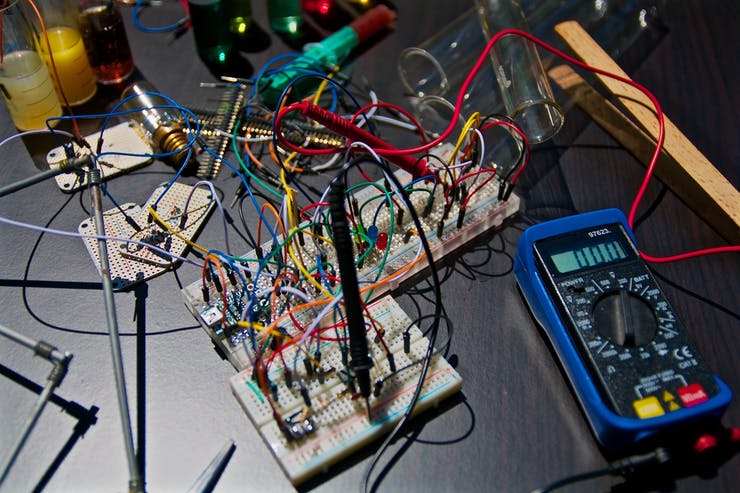
Don't mess with breadboard circuits for learning Arduino and coding, just connect the cables and start coding right now!
Theory and Animation Logic
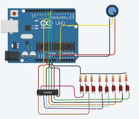
The Knight Rider effect (or "Larson Scanner") involves a light that bounces back and forth across a row of LEDs. In this project, we utilize the 74HC595 Shift Register to handle 12 LEDs using only three digital pins on the Arduino. This allows us to scale the project without consuming all available GPIOs.
Hardware Details
- Shift Register (74HC595): This 8-bit serial-in, parallel-out chip is the heart of the LED control logic. By sending bits serially, we can turn specific LEDs on or off in a high-speed sequence.
- Potentiometer Control: A rotary potentiometer is connected to an analog input (A0). This allows the user to manually adjust the scanning speed in real-time by varying the voltage between 0V and 5V.
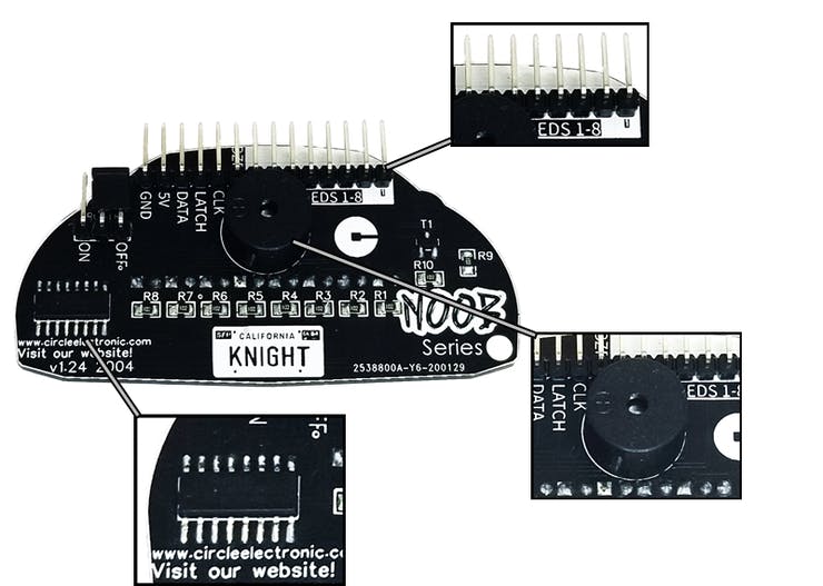
Meet the Circle Electronic NOOB Series Knight Rider!

https://www.circleelectronic.com/knight-rider
What can you do?
How to make this animation with pot?
Watch Youtube Video
https://www.tinkercad.com/things/6KD66LWNaAa
We will use 74hc595 Shift Register in this project.
So, how to make this animation with shift register.
Coding with Map and ShiftOut
The Arduino reads the analog value from the potentiometer (0-1023) and uses the map() function to translate this into a useful timing delay or a specific position in the LED sequence:
potvalue = map(potvalue, 0, 1023, 0, 11);
By mapping the 10-bit resolution of the ADC to the 12 positions of our LEDs, we can create an interactive scanner where the knob directly controls the position or speed of the light streak.
This is our code to make this animation with 74hc595. We will change this to make this with pot.
We change it like it:
#define DATA 8
Now we will read the data from pot
We will connect the pot middle pin to arduino analog 0 pin and read the datas
int pot=A0;
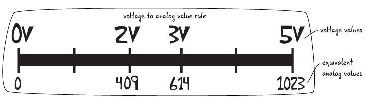
These are the data we get after making the connection. When we change the potentiometer, we read a value in the range 0-1023. We have to convert these values to 0-11.
We will use the map command to do this:
potvalue= map(potvalue,0,1023,0,11);
Now we are changing our code:
#define DATA 8
The final version of this code.
Circuit Diagram and Resources
- Tinkercad Link: Visual Simulation
- Product Details: Knight Rider Module
This project is an excellent entry point for learning how to use Shift Registers and Analog Input to create sophisticated visual effects with minimal wiring.
That's it!
Our Website: https://www.circleelectronic.com/
Github Page: https://github.com/circleelectronic/Knight-Rider
Blog Post: https://www.circleelectronic.com/post/arduino-knight-rider-with-potentiometer
Tinkercad Project Link: https://www.tinkercad.com/things/6KD66LWNaAa
Knight Rider Product Link: https://www.circleelectronic.com/knight-rider
Tindie Product Link: https://www.tindie.com/products/circle/knight-rider/