Introduction and Project Concept: Automatic Light On-Off System with Arduino
Hello inventors and engineers! Today, I'm going to take you through building a "Smart Light Sensor" system using an Arduino control board. The core idea of this project is to design a system that can respond to real-world environmental conditions. The LED will automatically light up when it detects that the light intensity in the room has decreased (entering a dark state). We can apply this principle to create an emergency backup lighting system or an automatic front porch light system for energy saving.
This is a project that seamlessly integrates physical devices (Hardware) and software processing, making it easy to understand for beginners.
Step 1: Hardware Preparation
To build this system, we need specific electronic components, especially for receiving Analog Signal values.
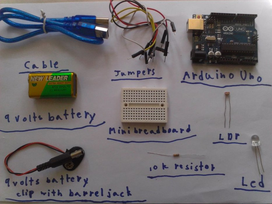
Key Components List:
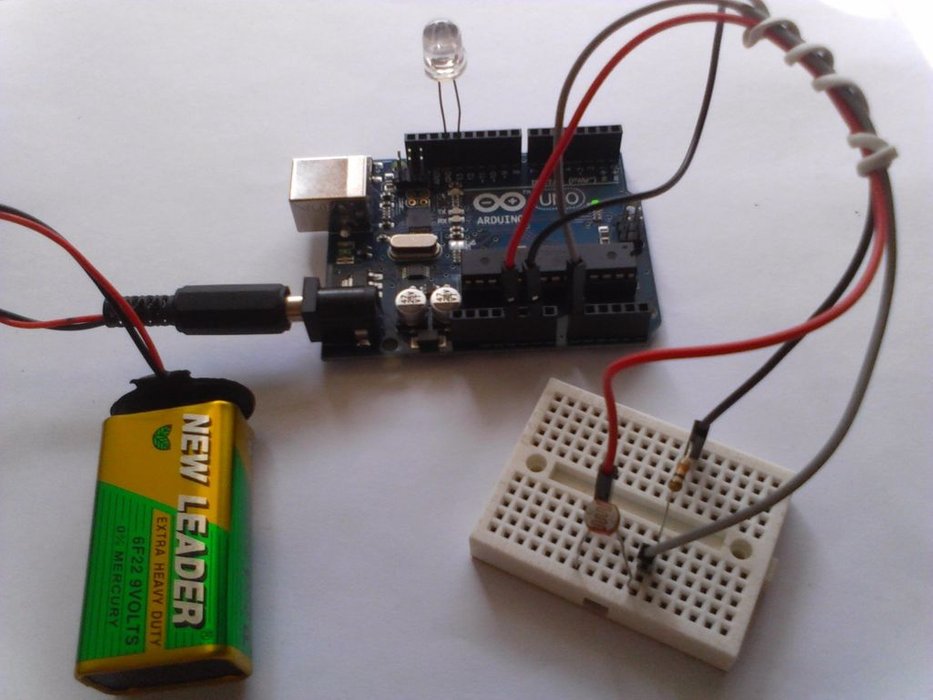
- Arduino UNO: The microcontroller board that serves as the main brain for processing light intensity values.
- LDR (Light Dependent Resistor): A light sensor, also known as a "photoresistor," whose resistance decreases with more light and increases in darkness.
- 10K Ohm Resistor: A fixed 10-kiloohm resistor used to create a Voltage Divider circuit, allowing Arduino to read changes as voltage levels.
- LED: An output device to simulate turning lights on and off.
- Mini Breadboard: For connecting circuits without soldering.
- Jumper Wires: For connecting signals between components.
- Power Supply (9V Battery with Barrel Jack): (Optional) For use in areas without a computer connection.
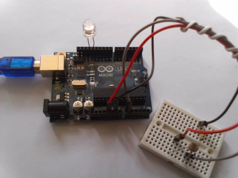
Step 2: The Circuit Design
The key to reading values from the LDR is to connect it in a Voltage Divider configuration, as Arduino cannot directly measure resistance but can measure Voltage through its Analog Input pins.
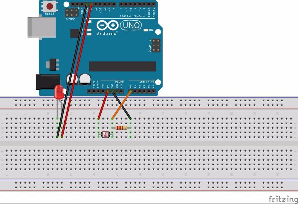
Connection Details:
- LED: The Cathode (Negative/short lead) connects to the Arduino's GND. The Anode (Positive/long lead) connects to Digital Pin 13.
- LDR and Voltage Divider Circuit:
- One leg of the LDR connects to the 5V power supply.
- The other leg of the LDR connects to Analog Pin A0, and at this same point, connect the 10K Ohm resistor to GND.
- Technical Insight: When light intensity changes, the LDR's resistance changes, causing the voltage across the 10K resistor to change accordingly (per Ohm's Law). This voltage value is what Arduino converts into a number between 0 and 1023.
Caution: Double-check the positive and ground connections carefully to prevent a Short Circuit, which could damage the microcontroller.
Step 3: The Code Logic & Calibration
Once the Hardware is ready, the next step is to write the code to control the operational logic.
Program Logic:
- Data Acquisition: We use the
analogRead(A0)function to receive the light intensity value, converted into a 10-bit digital signal (values 0-1023). - Display via Serial Monitor: Initially, upload the code and open the Serial Monitor (Ctrl+Shift+M) to observe the numerical values under different lighting conditions.
- When there is abundant light, the value displayed on the Serial Monitor will be high.
- When you cover the LDR with your hand (simulating darkness), the numerical value will decrease.
- Threshold Calibration: This is the most crucial part. From the data in the Serial Monitor, observe the values when it "starts to get dark."
- Example: If under normal light, you read a value of 180, and when dark, you read less than 150, you should set the Threshold to approximately 100-120 as a criterion for turning on the light.
- Output Control: Use the condition
if (sensorValue < threshold). If the read value is below our set threshold, send aHIGHsignal to Pin 13 to turn on the LED.
Engineer's Advice: Light intensity varies in different rooms. If you find that the LED is always on or doesn't dim at all, adjust the number 100 in the if condition of the code to match the actual minimum value you read from that environment for the highest accuracy of your sensor system.