Getting Started in the World of Embedded Systems: An LCD Project and First Soldering Experience
Stepping into the world of Embedded Systems often begins with projects that yield tangible results, and one of the most fundamental and crucial devices is the LCD (Liquid Crystal Display) screen. This project is not only a basic programming exercise but also a significant step in practicing hardware skills, namely "soldering," which is a core skill for electronics engineers.
Deep Dive into System Operation
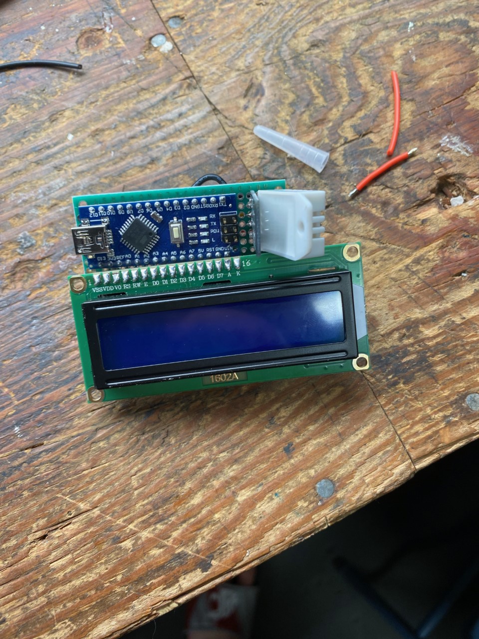
In this project, we chose to use a standard character LCD, which typically employs the industry-standard HD44780 controller chip. The key aspects of the connection are as follows:
- Data Communication: This LCD works with Arduino using the
LiquidCrystal.hlibrary, which allows selecting both 8-bit and 4-bit data transfer modes to save pins on the control board. - Contrast Adjustment: This is where beginners most often encounter problems. If you find that the screen powers on but doesn't display characters, or only shows black blocks, check the Potentiometer (variable resistor).
If you are having issues with the LCD screen turn knob on the potentiometer until the screen displays the desired message.
From an engineering perspective, pin V0 (Pin 3) on the LCD screen serves to receive reference voltage to determine the alignment angle of the Liquid Crystals. Turning the Potentiometer creates a Voltage Divider circuit to adjust the supply voltage level for the clearest viewing angle.
Lessons from Soldering (Soldering Milestone)
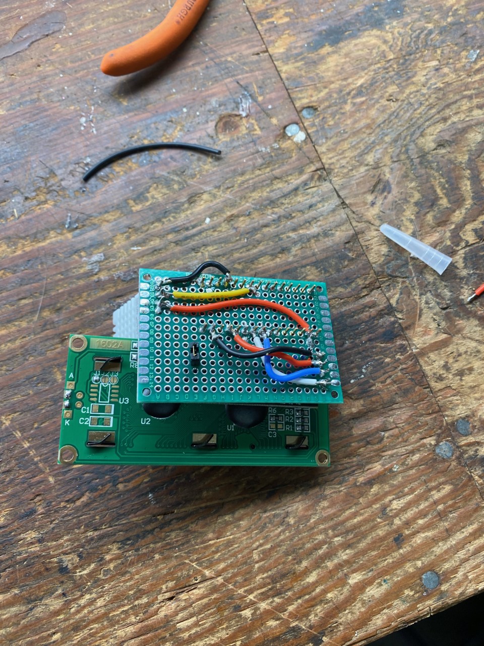
The image above shows the result of the first soldering work, which is a significant turning point from experimenting on a Breadboard to building durable and truly functional devices:
- Header Pins: Soldering header pins (Male Headers) onto the LCD module requires precision and appropriate heat control to prevent the circuit traces (Pad) from lifting or being damaged.
- Solder Joint Quality: A good solder joint should have a shiny "volcano shape," indicating good electrical conductivity and strong mechanical adhesion.
Software Logic
The program starts with Initialization to set initial values for the HD44780 chip, specifying how many rows and columns will be used (e.g., 16x2). Then the logic proceeds as follows:
- Set Cursor: Sets the coordinate position (Column, Row) where characters should appear.
- Data Transmission: Sends ASCII codes of characters to the screen's Buffer.
- Display Refresh: The screen will retain the character's state until a clear screen command (Clear) or overwriting in the same position occurs.
This project serves as an excellent foundation for understanding Hardware-Software Interaction, which will lead to the development of more complex User Interfaces in the future.