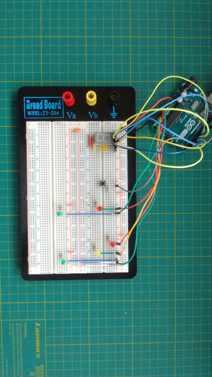
This is an educational project for beginners. It’s a traffic light, but definitely not a simple one. This project features a pedestrian traffic light and a regular traffic light working together. There is also a display showing the pedestrian when the lights will turn red again. A push button was added to receive a request when the pedestrian wants to cross the street. Here is the tricky part. If a pedestrian makes a request and crosses the street, the car lights will turn red. Only 30 seconds later, if a pedestrian makes another request, the pedestrian lights will turn green again.
Chronological Sequencing: The Traffic Light FSM
Building a traffic light sequence utilizing delay(1000) creates a fundamentally disastrous urban design! If a pedestrian furiously smashes the "Walk" button while the Arduino is trapped inside a massive 15-second delay() holding a Green Light, the processor completely ignores them, and they are forced to literally wait until the loop resets! The Pedestrian Crossing Traffic Lights completely burns delay() out of exactly the core architecture. Natively utilizing millis() inside a stringent Finite State Machine (FSM), the Arduino watches both the Traffic Light Clock AND the immediate physical Pedestrian Button state simultaneously, 100% concurrently!
The Non-Blocking millis() Execution Core
The delay() function heavily paralyzes the entire silicon core violently. millis() acts as an absolute stopwatch running silently in the deep background.
- The Arduino checks the stopwatch over a million times a second without stopping!
if (currentTime - previousTime >= 5000){ Yellow Light! }- But simultaneously, INSIDE the exact same loop, it rapidly checks
if (digitalRead(BUTTON) == LOW)!
unsigned long previousMillis = 0;
const long greenTime = 10000; // 10 seconds of traffic flow natively.

boolean pedestrianWaiting = false;

void loop() {
  unsigned long currentMillis = millis(); // Check the watch!

  // The brutal BUTTON INTERCEPTOR! Never blocking!
  if (digitalRead(pedButton) == LOW) {
    pedestrianWaiting = true; // Flag the system!
  }

  // If the Green time is fully organically up... OR a pedestrian forced an early interrupt!
  if (currentMillis - previousMillis >= greenTime || (pedestrianWaiting && currentMillis - previousMillis >= 3000)) {
    // If they walk-button was pressed, immediately force Yellow light after 3 baseline seconds!
    triggerYellowProtocol();
    triggerPedestrianWalk(); // Safely halt traffic entirely!

    pedestrianWaiting = false; // Reset the flag cleanly!
    previousMillis = currentMillis; // Reset the stopwatch!
  }
}
Simulating Real-World Hardware Interfaces
A real traffic light system operates on 240VAC using massive contactors.
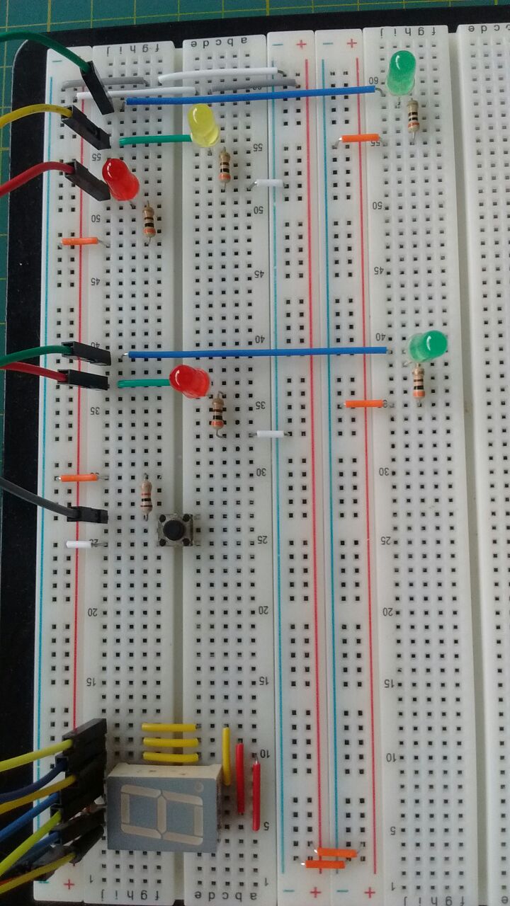
- To simulate this miniature array cleanly, the Arduino drives explicit 5mm LEDs.
- Resistor Mandatory Matrix: Every single LED (Red, Yellow, Green, Ped-Red, Ped-Green) absolutely MUST have its own independent
220-Ohmresistor wired strictly in physical series! - DO NOT tie all LED negative legs into one shared resistor. Because Red requires ~2V and Green requires ~3.2V, tying them together causes intense electrical conflict, heavily reducing brightness and unpredictably frying the Green LED's delicate semiconductor doping layer!
Civil Infrastructure Modeling Toolset
- Arduino Uno/Nano (Handling the high-speed multitasking FSM natively!).
- Large Tactile Arcade Button (To violently simulate an impatient pedestrian explicitly demanding their Walk symbol).
- LED Array (Red, Yellow, Green) x2 (One set specifically for Car Traffic, another specific set [Red/Green] specifically for Pedestrians).
- Multiple 220-Ohm / 330-Ohm Resistors (Perfectly isolating the individual colored voltage drops seamlessly).
- A Deep Understanding of FSM Logic Matrices (This project fundamentally teaches the most critical C++ embedded programming concept: "State Machines" without blocking functions!).