Arduino Power meter system with Internal PLC
Heavy Grid Analytics: The Arduino Power Meter
Plugging massive air conditioners or crypto-mining rigs directly into a weak household circuit invites rapid thermal degradation and electrical fires. The Arduino Power Meter System intercepts and calculates absolutely huge physical grid parameters safely! By clamping a non-invasive SCT-013 Split-Core Current Transformer securely around the Main AC Phase wire in the breaker box, the hardware acts identically to a massive industrial clamp-meter! It inductively reads the 220V magnetic fields flowing across the home, mathematically translates the microscopic AC induction voltage completely inside the Arduino processor perfectly, and aggressively calculates exact real-time Wattage consumption natively!
Non-Invasive Induction Math (EmonLib.h)
You absolutely do NOT strip wires and connect 240V AC Mains power directly into the Arduino; the explosion would be catastrophic!
- The SCT-013 Clamp detects the magnetic field generated by current flowing through the target wire, producing an incredibly tiny, proportional micro-voltage!
- Because AC power produces a violent Sine Wave (shifting from positive to negative), the Arduino analog pin (
0-5V) cannot read the negative-2.5Vswing at all natively! - You MUST construct an aggressive Voltage Biasing Circuit (Two 10K resistors forming a divider) to pull the baseline signal physically up to
2.5 Volts. Now the AC wave swings safely between0Vand5Ventirely!
#include "EmonLib.h"                   // Include heavy AC interpolation library natively!
EnergyMonitor emon1;                   // Instantiate the core object

void setup() {
  Serial.begin(9600);
  emon1.current(A0, 111.1);            // Calibrate: Current: Input pin, Calibration value.
}

void loop() {
  // Demand the processor sample the sine wave exactly 1480 times recursively!
  double Irms = emon1.calcIrms(1480);  // Calculate the Root-Mean-Square (RMS) Amp flow!

  double powerWattage = Irms * 230.0;  // P = I * V (Assuming global 230V AC Grid Matrix!)

  Serial.print("Current: ");
  Serial.print(Irms);
  Serial.print(" A | Power: ");
  Serial.print(powerWattage);
  Serial.println(" Watts");
}
Power Line Communication (PLC) Injection
If the power meter exists inside an isolated concrete basement breaker box, Wi-Fi will entirely fail.
- Industrial systems exploit internal PLC (Power Line Communication)!
- Modules like the
KQ-130Fliterally inject serial data strings ("HOUSE LOAD: 4000W") physically entirely into exactly the 220V/110V copper power lines natively! - You plug a second
KQ-130Fmodule into a standard wall socket upstairs. It aggressively filters out the 50Hz AC wave, extracts the high-frequency Serial payload, and decodes the wattage directly onto your kitchen LCD securely natively!
High-Voltage Safety Hardware Matrix
- Arduino Uno/Nano (Calculating the violent multidimensional sampling math loops exactly natively).
- SCT-013-000 Non-invasive AC Current Sensor (Ensure you clamp it entirely around ONLY the Live/Phase wire! Clamping both Live and Neutral simultaneously forces the magnetic fields to completely cancel each other out natively, returning exactly 0.0 Amps!).
- Voltage Biasing Network (Two
10K-Ohmresistors and a10µFCapacitor absolutely mandatory to offset the negative AC sine wave). - KQ-130F Power Line Communication Module (Optional, executes terrifyingly robust data-routing exclusively through the physical household copper grid entirely).
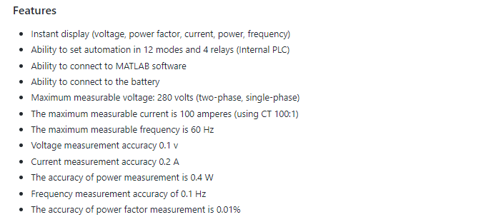
System Features and Modifications
point 1: By changing the resistances of R17 and R16 in PZEM, it is possible to measure the voltage of more than 280 volts (This is a voltage divider circuit). For example, if R17 is equal to 2 megaohms and R16 is equal to 750 ohms, the voltage can be measured up to 500 volts. It is also necessary to make changes in the Arduino codes, Additional information in the folder 500 volts in github
point 2: This system also supports Modbus protocol. You can add this potkal to it. And it was in contact with other industrial equipment such as HME and PLCs
Test video
Connecting power meter to MATLAB and view the data on the chart
voltage measurement test
current measurement test
Relay function test
Internal PLC settings :
To access the settings menu, we must first turn the MODE key on and set the required parameters with the arrow keys.
| parameter in the settings menu | use |
|---|---|
| OVER Voltage | Maximum voltage limit |
| LOW Voltage | Minimum voltage |
| OVER Current | maximum current limit |
| LOW Frequency | minimum frequency |
| OVER Frequency | Maximum frequency limit |
| LOW POWER FACTOR 1 | steps, one power factors |
| LOW POWER FACTOR 2 | steps, two power factors |
| LOW POWER FACTOR 3 | steps, three power factors |
| TMS 1 SET | timer relay one |
| TMS 2 SET | timer relay two |
| TMS 3 SET | timer relay three |
| TMS 4 SET | timer relay four |
| R1 | set the operation mode of relay one |
| R2 | set the operation mode of relay two |
| R3 | set the operation mode of relay three |
| R4 | set the operation mode of relay four |
After making the settings, turn the MODE key to the off position so that the data is stored in the permanent memory of the controller
- Each relay timer unit is 100 milliseconds
-A variety of performance modes (R1,R2,R3,R4):
1- reverse time overcurrent function 2- Additional constant time flow function 3-Overvoltage function 4- voltage reduction function 5- frequency reduction function 6- frequency increase function 7- Function of the function of going out of normal mode (frequency, voltage, current) 8-Function of power factor steps of one 9-Function of power factor steps of two 10- Function of power factor steps of three 11-The operation of voltage out of normal mode 12- Function of frequency out of normal mode
#########################################################################
Github link : https://github.com/amir-eshaqy/pz