Arduino based burglary zone input tester, an experimental design for testing hardwired connected sensors.
Compromising hardwired connections:
As the hardware zone loop is powered by a constant voltage level delivered by the burglary
control unit or a zone ex-pander, it is very easy build and to apply a devices that can read and remember the voltage level in the zone loop, and later, on a request, feed it back to the zone loop.
Fig. 1 presents a schematic of a device that can be used to compromise a burglary alarm system with a wired zone loop powered by a constant voltage level.
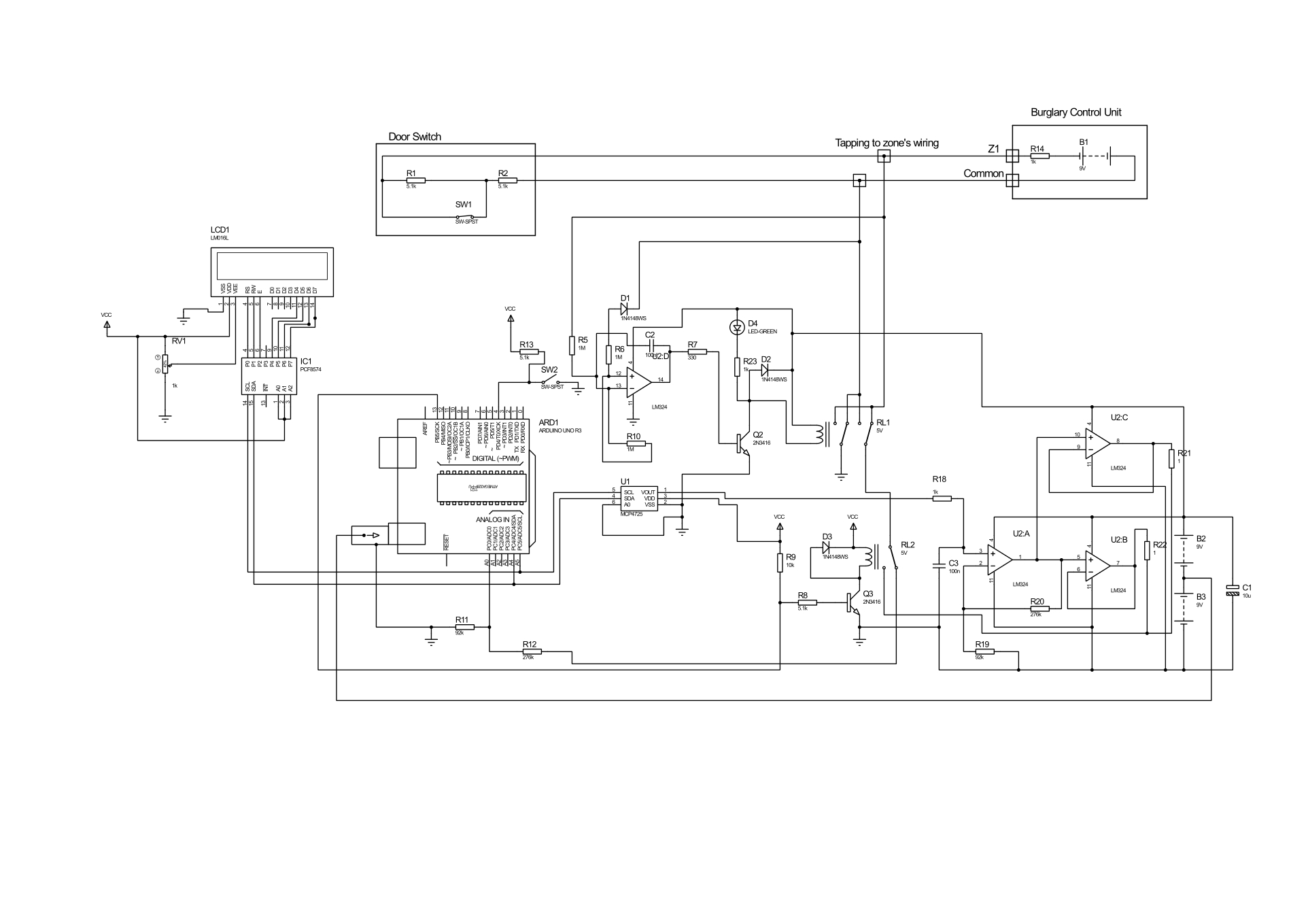
After connecting to the zone wires (tapping connectors to zone loop wires), circuit first checks for connection’s polarity. This is done by sub-circuits with operational amplifier U2D, with resistors R10, R5, R6, diode D1 and capacitor C2. If measured voltage on R10 it is negative, will automatically reverse input by drawing transistor Q2and switched relay RL1 and D4 as LED lights ON.
If someone wants to bypass this sub-circuits, needs to measure polarity or modify circuits to measure the positive and negative polarity as well supply back voltage of the negative or positive polarity.
The sub-circuit R12and R11 measures an actual zone input voltage thorough the relay contacts of RL1 and RL2. Relay RL2 will switches when we decide to change status from reading a zone loop voltage to attacking a zone loop input of burglar alarm system.
The LCD1 display will print the measured voltage level of a zone loop. Its receive measure data through the I2C’s communication from the Arduino Uno micro-controller.
The voltage input/output divider (R11/R11 + R12) was set for ratio 1:4 for AD input voltage level requirements.
When SW2 switch is on, the Arduino Uno supplies voltage at a level as was measured to the zone loop wires through the D/A interface based on MCP4725interface and the amplifiers. The amplifier U2A with resistors R19and R20 amplify input 4 times and supplies it to the buffering amplifiers U2B and U2C (outputs connected in parallel) with output voltage level that equals to the measured on a zone loop. These voltage now is presented on a zone loop, and switching SW1 should not change zone input of a burglary unit. In most cases the attack should result with success of a 90 % of the modern burglary alarm systems.
Switch SW1 simulates a door contact open/close status if some one wants to play with circuits in a a circuits simulation program and do not forget to add a grounding referenced resistors as the device itself presets floating type voltage source.
LCD1 and IC1is a sub-circuits of Liquid Crystal_I2C lcd Arduino sketch (model -ywrobot arduino lcm1602 IIC V1).
The code for Arduino is presented below:
The codes for a Liquid Crystal_I2C lcd display and DAC was found on the INTERNET.
Delays of 200 was used for relay to stabilize, 500 for LCD display and of 20000 for a compromising timing limits and can be change as require.
Loaded Libraries:
NewLiquidCrystal
// or LiquidCrystal
Wire
/*
Configuration bytes:
//12-bit device values from 0-4095
//page 18-19 spec sheet
buffer[0] = 0b01000000; // control byte
//bits 7-5; 010 write DAC; 011 write DAC and EEPROM
//bits 4-3 unused
// bit0 unused
buffer[1] = 0b00000000; //HIGH data
//bits 7-0 D11-D4
buffer[2] = 0b00000000; // LOW data
//bits 7-4 D3-D0
//bits 3-0 unused
*/
#include
#defineMCP4725 0x60 // MCP4725 base address
bytebuffer[3];
unsignedint val;
#include
#include
#include
#include
#include
LiquidCrystal_I2Clcd(0x27, 2, 1, 0, 4, 5, 6, 7, 3, POSITIVE); // Setup lcd
//LiquidCrystal_I2C lcd(0x27, 16, 2) lcd address may be diferent as toa lcd vendor specyfication
voidsetup() {
pinMode( 4, INPUT); //pin to starts measurement
pinMode(13, OUTPUT); //Relay swith ON to startcompromising
pinMode(A0, INPUT); // pin as Analog IN to measure zone loop voltage
} //end setup
voidloop() {
int u= 0;
intval = 0;
buffer[0] = 0b01000000; // control byte
delay(200);//Wait
u= analogRead(0);
val = u* 4; // read pot
buffer[1] = val >> 4; // MSB 11-4 shift right 4 places
buffer[2] = val << 4; // LSB 3-0 shift left 4 places
floatsensorValue = 0;
sensorValue = u*(5.0/1023.0)*4;
Wire.begin(); // begin I2C
lcd.begin(16, 2);
lcd.backlight();
lcd.setCursor(0, 0);
lcd.print("Measured VoltS =");
lcd.setCursor(0, 1);
lcd.print(sensorValue);
lcd.print("__");
lcd.print(u);
delay(500);
while(digitalRead(4) == LOW) {
//digitalWrite(2, HIGH); //ready LED ON, option
delay(200);//delay for conats to sabilize
Wire.beginTransmission(MCP4725); // address device
Wire.write(buffer[0]); // pointer
Wire.write(buffer[1]); // 8 MSB
Wire.write(buffer[2]); // 4 LSB
Wire.endTransmission();
delay(200);//Wait
digitalWrite(13, HIGH); //Relay 2 ON to compromise burglary zoneloop
delay(20000);//Wait
}
} // end loop
EXPANDED TECHNICAL DETAILS
Security System Diagnostics
This diagnostic tool is designed to test the integrity of security circuit zones in a professional alarm installation.
- EOL (End-of-Line) Resistor Analysis: Professional alarm systems use specific resistance values (e.g., 2.2kΩ, 4.7kΩ) to detect tampering. This tester uses the Arduino's ADC to measure the resistance of the zone.
- State Identification: The firmware identifies four distinct states: Healthy (Closed), Alarm (Open), Tamper (Short Circuit), and Tamper (Wire Cut).
Benchmarking Tool
- Real-Time Display: An I2C 16x2 LCD shows the live Ohm reading and the current zone status.
- Interaction: Includes a toggle switch to simulate different fault conditions, making it an essential training and calibration tool for security technicians.