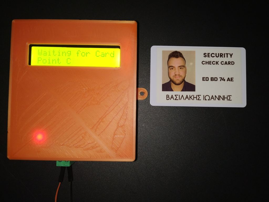
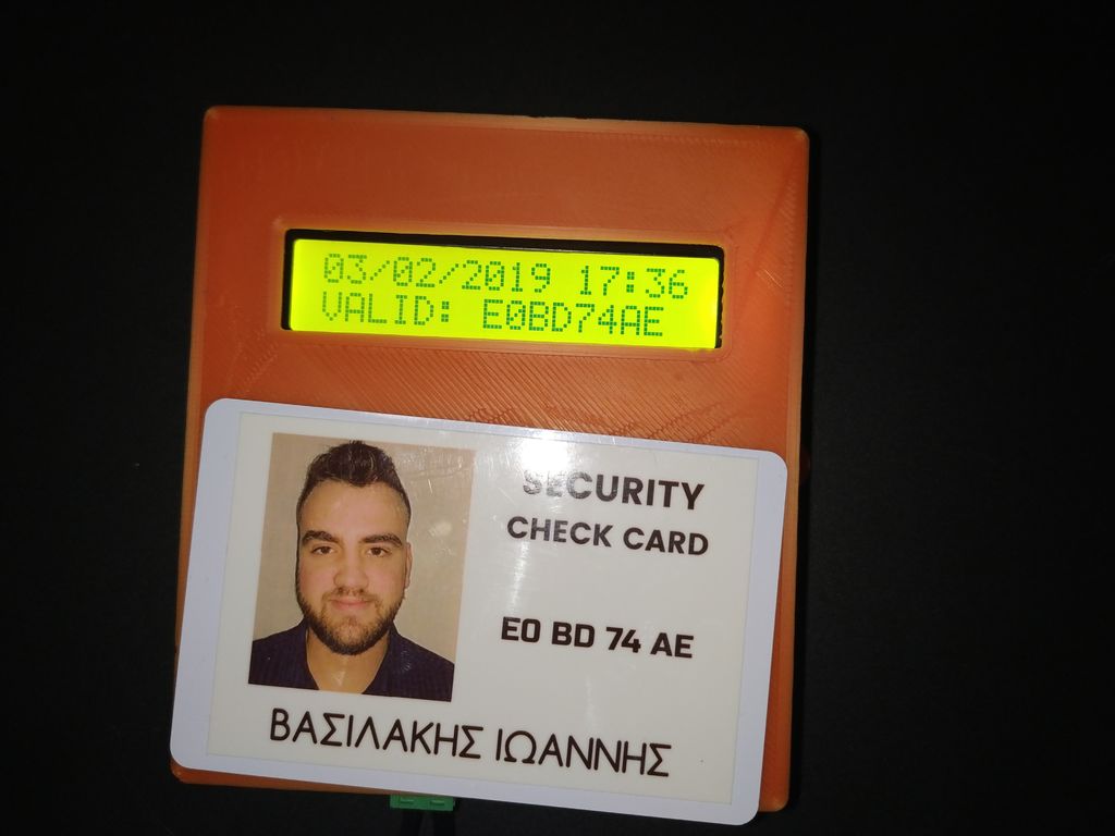
You can use this system in areas with security guards (e.g., warehouses, malls, open areas). Every guard will have a personal RFID card with a unique ID number. When a security guard passes his card over the Check point station - the ID and the current time/date will be stored inside the controller memory (EEPROM). The security guard inside the "Control Room" can read the report of all check point stations with only one click!
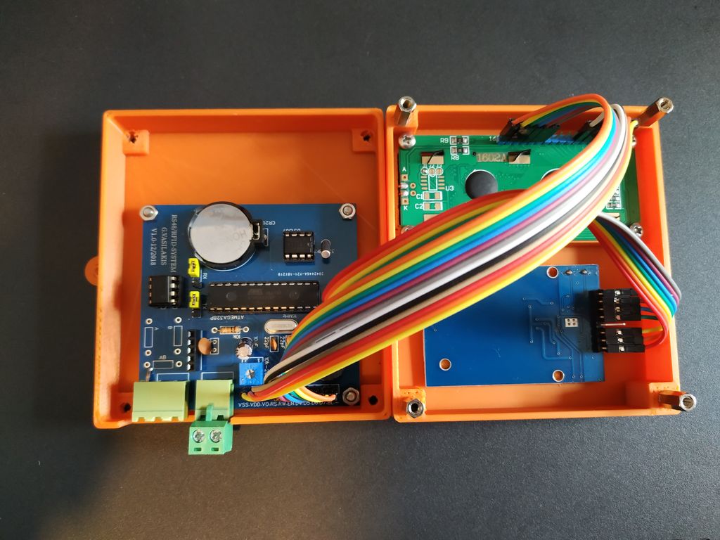
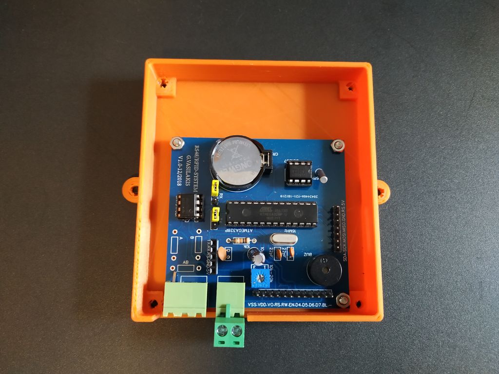
We used the RFID technology to read scanned cards and the RS485 electrical data bus protocol for communication. In this project, I decided to make my own PCB that is based on the Arduino UNO microcontroller - ATmega328P.
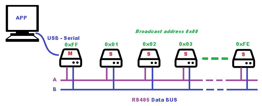
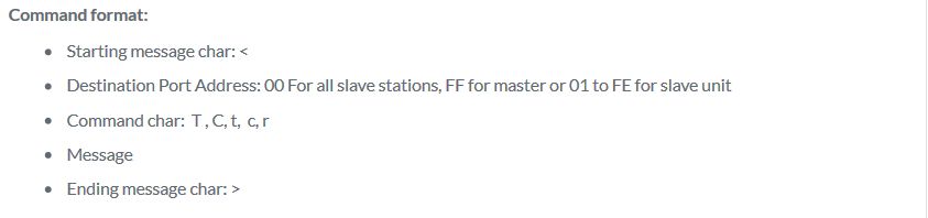
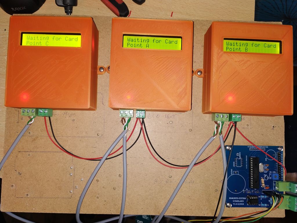
We can have up to 254 slave-check point stations and one master station in the RS485 data bus. The master station is communicating with one computer in the security room via a serial USB port. We will describe the communication protocol in the following steps!
Let's get started.
Project Perspective
This Arduino RFID System Based on RS485 is an innovative and creative security check system project. By using multiple checkpoint stations (slaves) and a central monitoring station (master) connected via a robust RS485 network, you can build a more organized and easy-to-use security solution for your home or office.
Technical Implementation: RS485 Networking
The project focuses on creating a high-performance and reliable security network:
- Networking layer: RS485 is a robust communication standard that allows several Arduinos to communicate over long distances using only two wires.
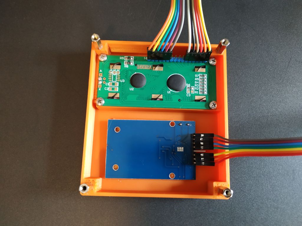
- Sensing layer: Using RFID-RC522 Modules, you can accurately identify and manage users or checkpoint visits across the entire network.
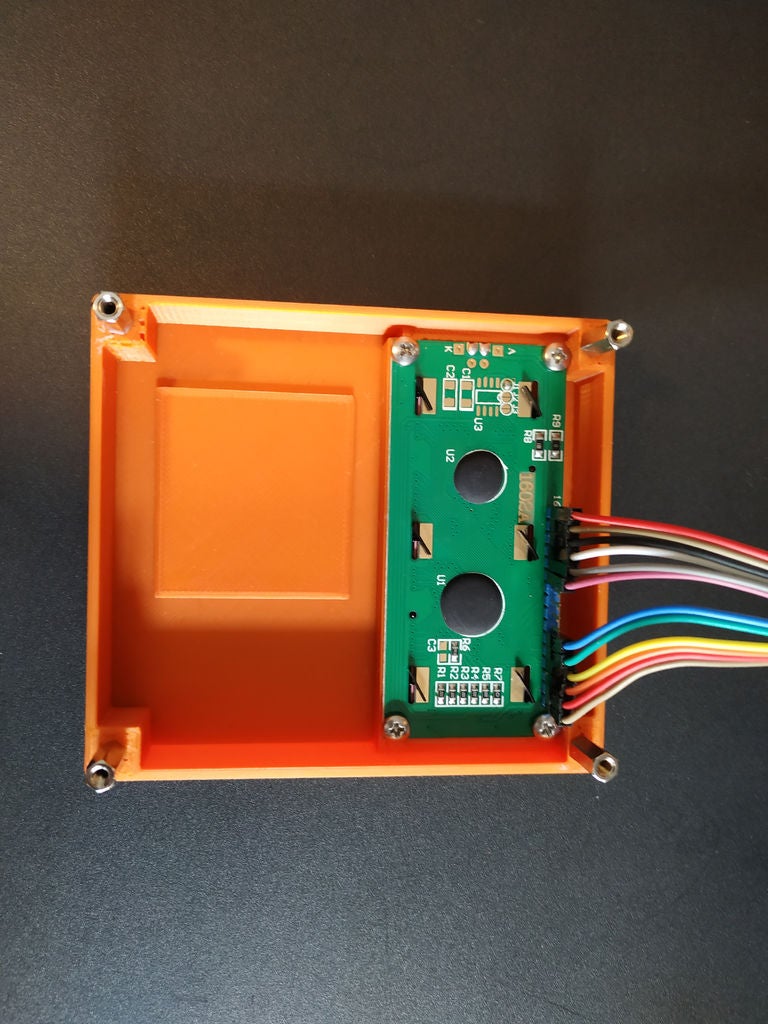
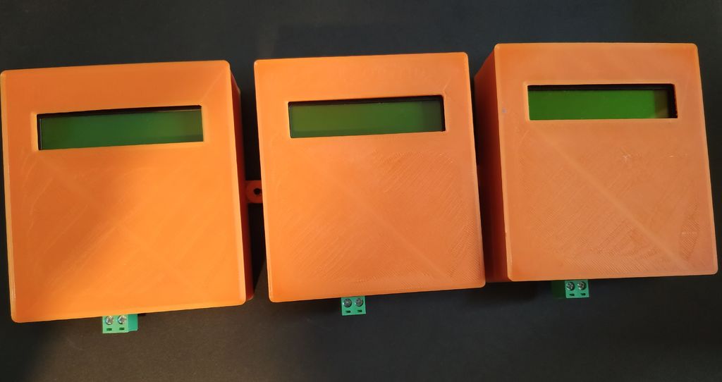
- Master-Slave Architecture: A central Master Arduino coordinates all the checkpoint data from several Slave Arduinos and displays it on an LCD 16x2.
Hardware Infrastructure
- Arduino Uno (Master/Slave): These boards act as the main hubs for the checkpoint data and coordinate all communication across the network.
- MAX485 Modules: These specialized transceivers provide the necessary hardware for RS485 communication.
- RFID-RC522 Modules: Providing accurate digital ID verification and checkpoint scanning.
- LCD 16x2 Display: Provides a clear and versatile way for the master to show all system metrics and telemetry.
- Micro-USB Cable: Use to program each Arduino directly from your computer.
Step-by-Step Selection and Search
The networking process is designed to be clear and efficient:
- Initialize Master: SETUP the Master Arduino with the LCD display and its RS485 communication parameters.
- Setup Slaves: Configure each Slave Arduino with a unique ID and its local RFID sensor.
- Network Connection: Correctly wire each RS485 module into a daisy-chain network using the two-wire bus.
- Code and Deploy: Upload the master and slave codes using the Arduino IDE and start monitoring your checkpoint visits.
Future Expansion
- Custom Access Control Integration: Add electronic locks or servos to trigger specific security responses for valid RFID cards.
- Cloud Database Support: Connect the master Arduino to a cloud database (e.g., Firebase) for remote security logging and reporting.
- Biometric Security Integration: Add fingerprint sensors or facial recognition to create a more robust multi-factor security environment.
- Voice Control Alert Support: Use a voice assistant like Alexa or Google Assistant to receive security alerts and notifications from your network.
This Arduino RFID System Based on RS485 is a perfect project for any electronics enthusiast looking for a more interactive and engaging security tool!
~Project link can be found here:
https://www.ardumotive.com/arduino-security-check-system-en.html#
Video presentation: