Overview
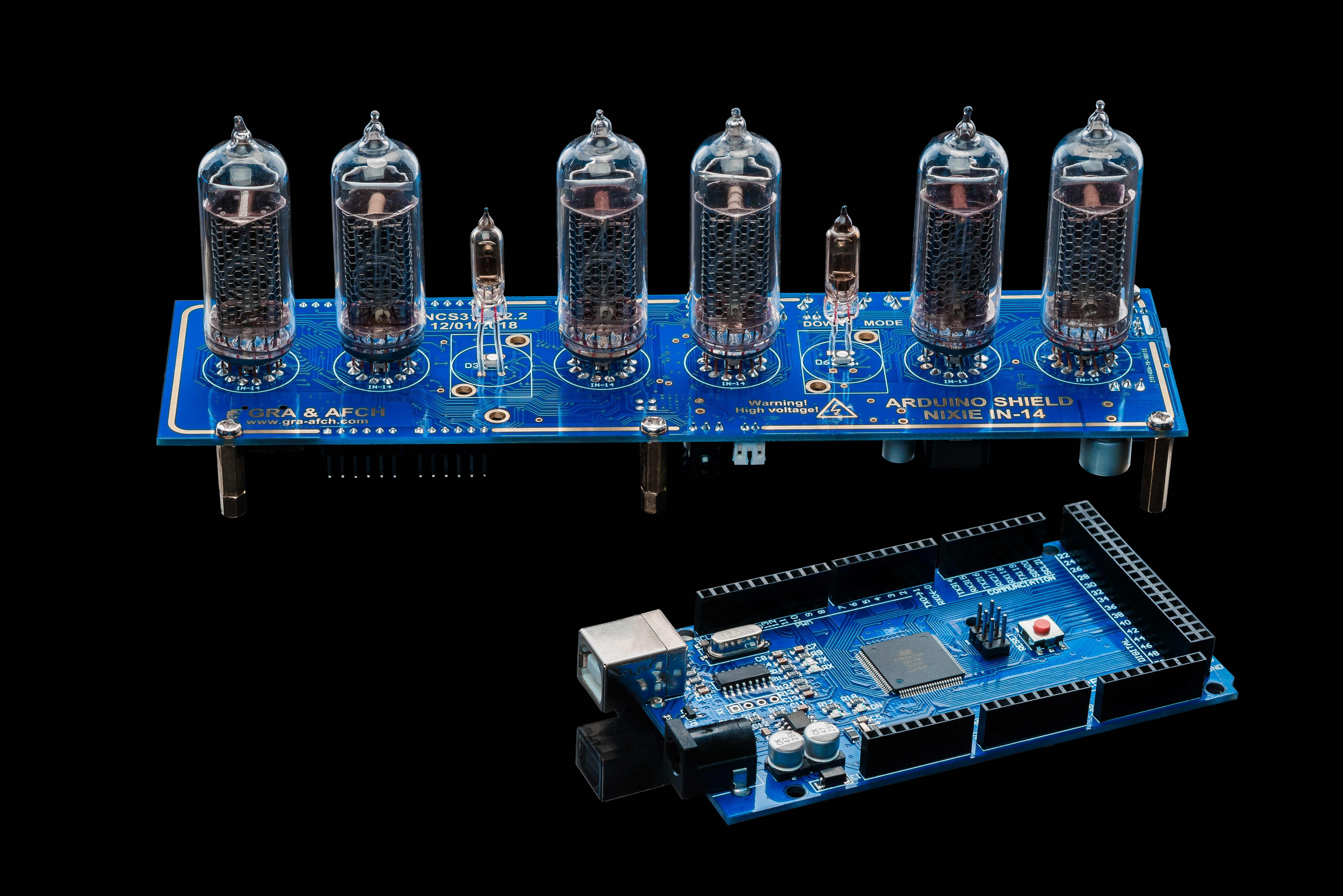
Initially, after we had access to almost inexhaustible supply of excellent quality Soviet Nixie tubes IN-12, IN-14 and IN-18, there was going to make a simple display of the Nixie tubes as Shield for Arduino. Arduino at that time we already had, so that the case remained for small (so we thought at the time). At that time we did not know anything about how to deal with such lamps.
Extreme 170V Cathodes: Arduino Nixie Tube Clock
Normal clocks use 5V LEDs. The Nixie Tubes Clock uses physically dangerous, 1960s Cold War-era Soviet Union technology! Nixie tubes (like the iconic IN-14) contain glowing neon gas and physical wire meshes shaped exactly like the numbers 0 through 9. To make the numbers glow fiery orange, the Arduino cannot send a 5V logic signal; it must aggressively actuate terrifying 170V DC physical ignition sequences utilizing complex K155ID1 / 74141 BCD-to-Decimal High-Voltage decoder chips!
Very quickly we found on the internet scheme of powering such tubes:
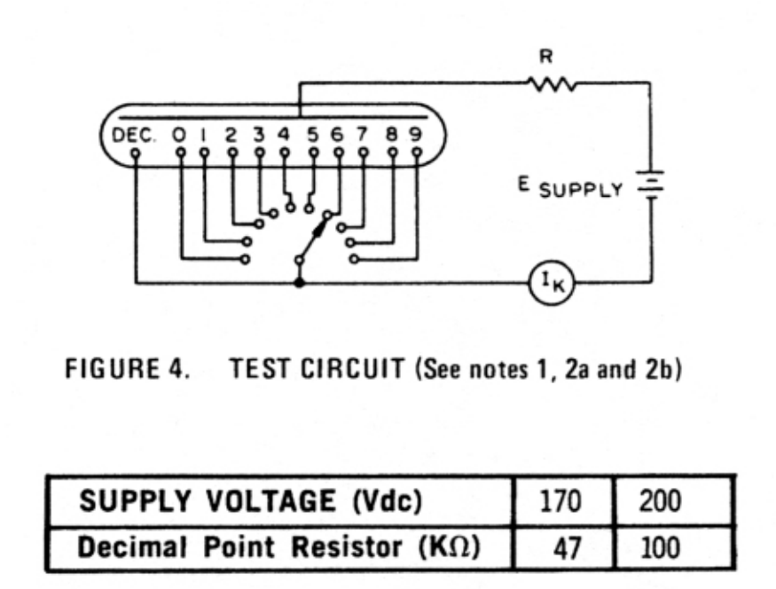
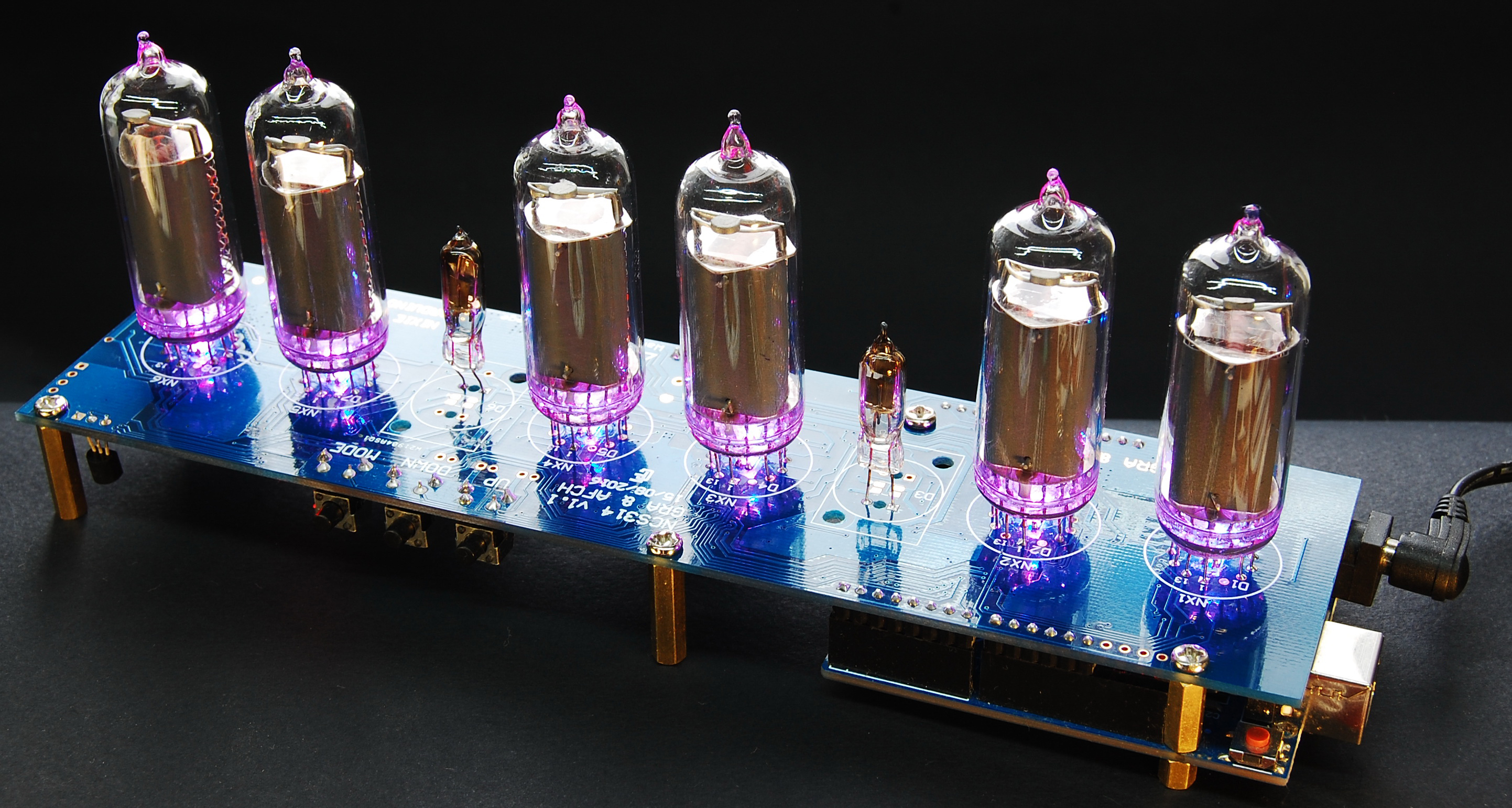
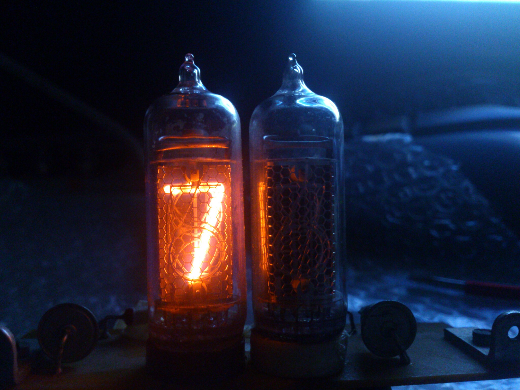
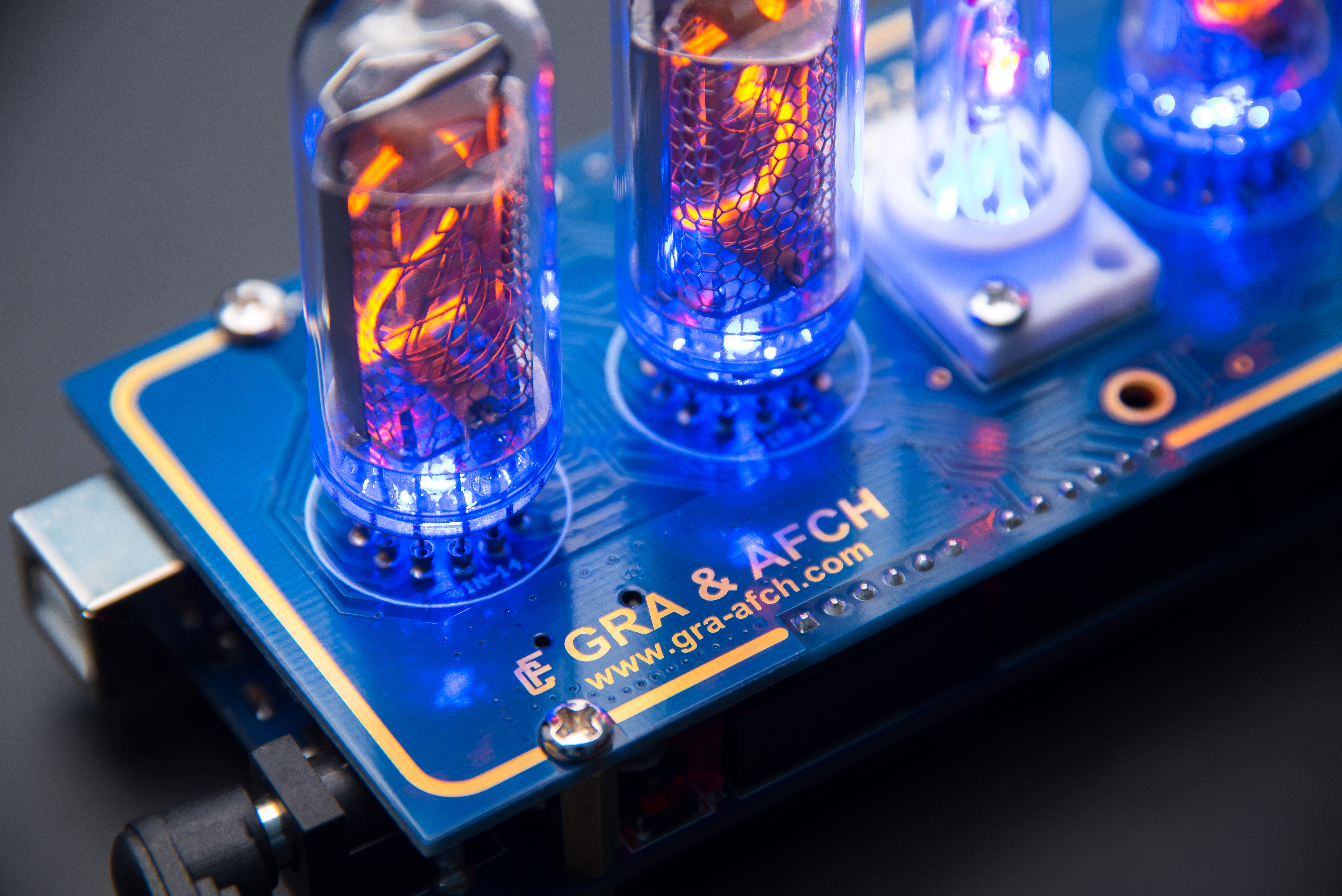
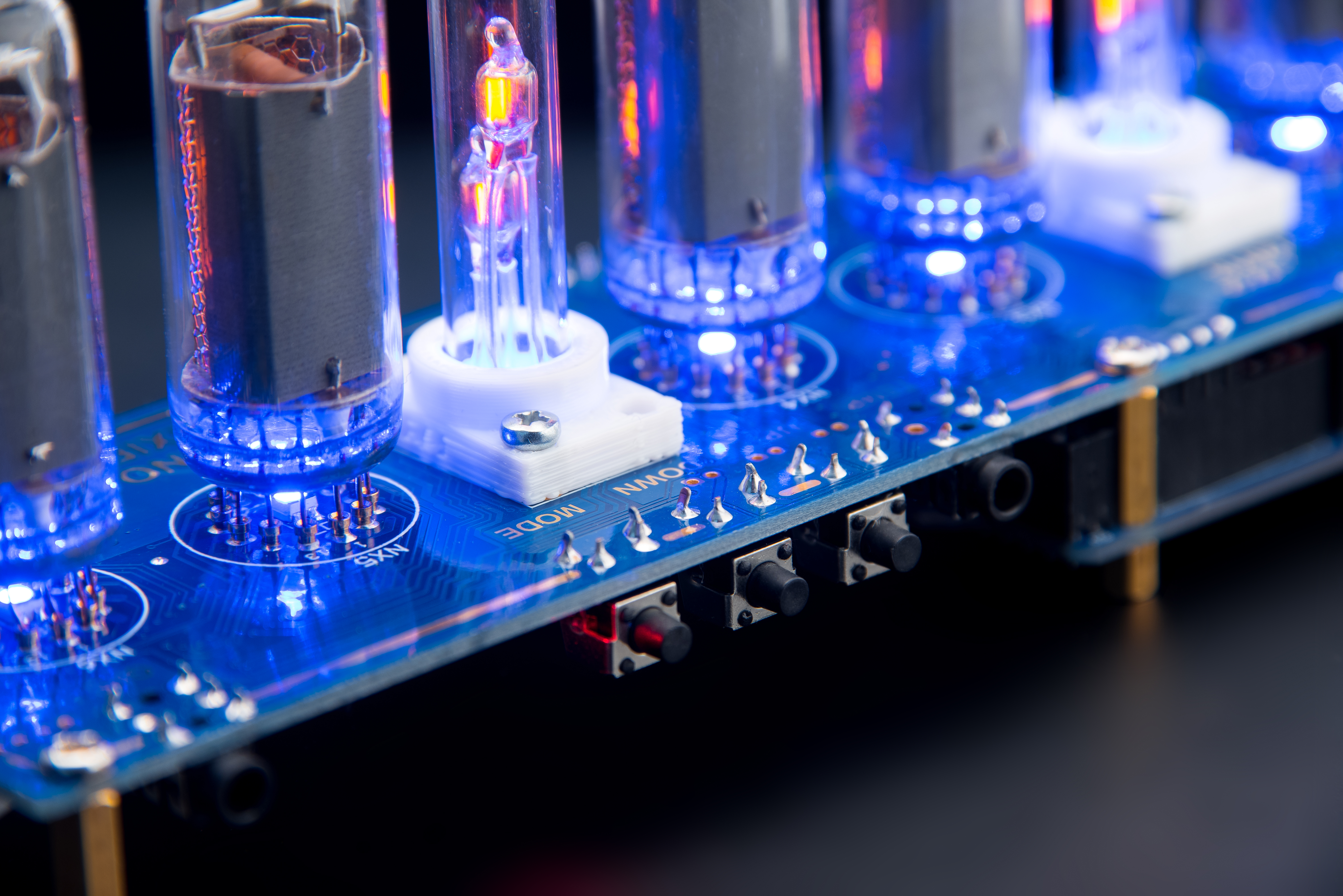
YES! It shines! The fact that we saw just stunned us is like a small miracle, and we realized that we are on the right track. Immediately began the photo session:
High-Voltage DC Execution (The Boost Converter)
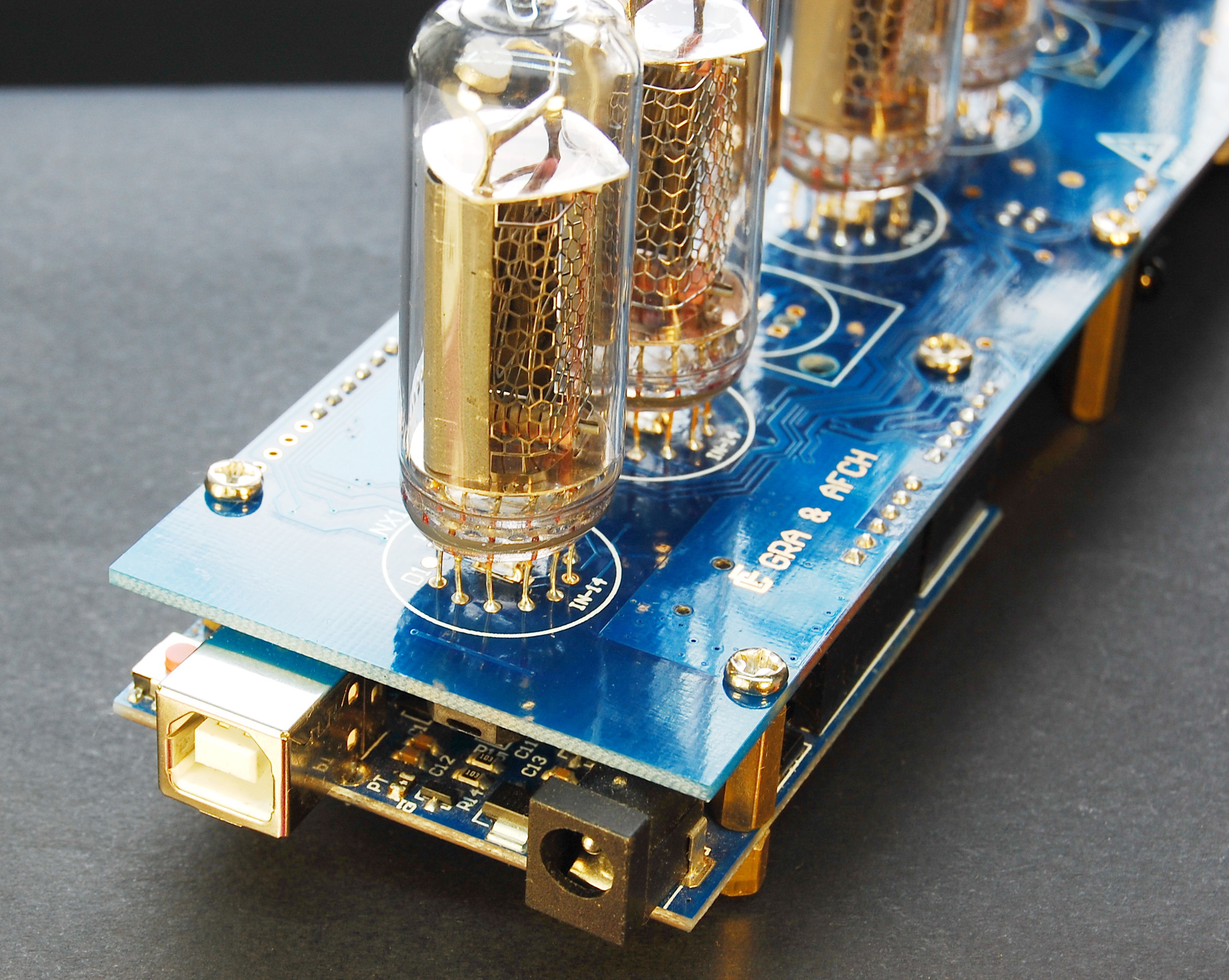
You plug a standard 12V DC power supply into the massive Arduino Shield.
- The 12V natively powers the Uno processor safely.
- The shield literally features a terrifying High-Voltage Step-Up Boost Switcher built in! It violently ramps the voltage up to exactly
170 Volts DC. - The Cathode Trap: You connect the massive
170V Anodedirectly to the glass tube! - But wait, if you run the
170Vback out into the tiny ArduinoD5pin, the chip instantly explodes into literal fire! - The Arduino uses entirely discrete K155ID1 Decoder Chips. These tiny chips can withstand 170 Volts on their outputs! The Arduino safely sends merely a 4-bit
5Vbinary sequence (0b0101for the number '5'), and the K155ID1 physically connects theCathode 5to Ground, completing the massive 170V neon circuit!
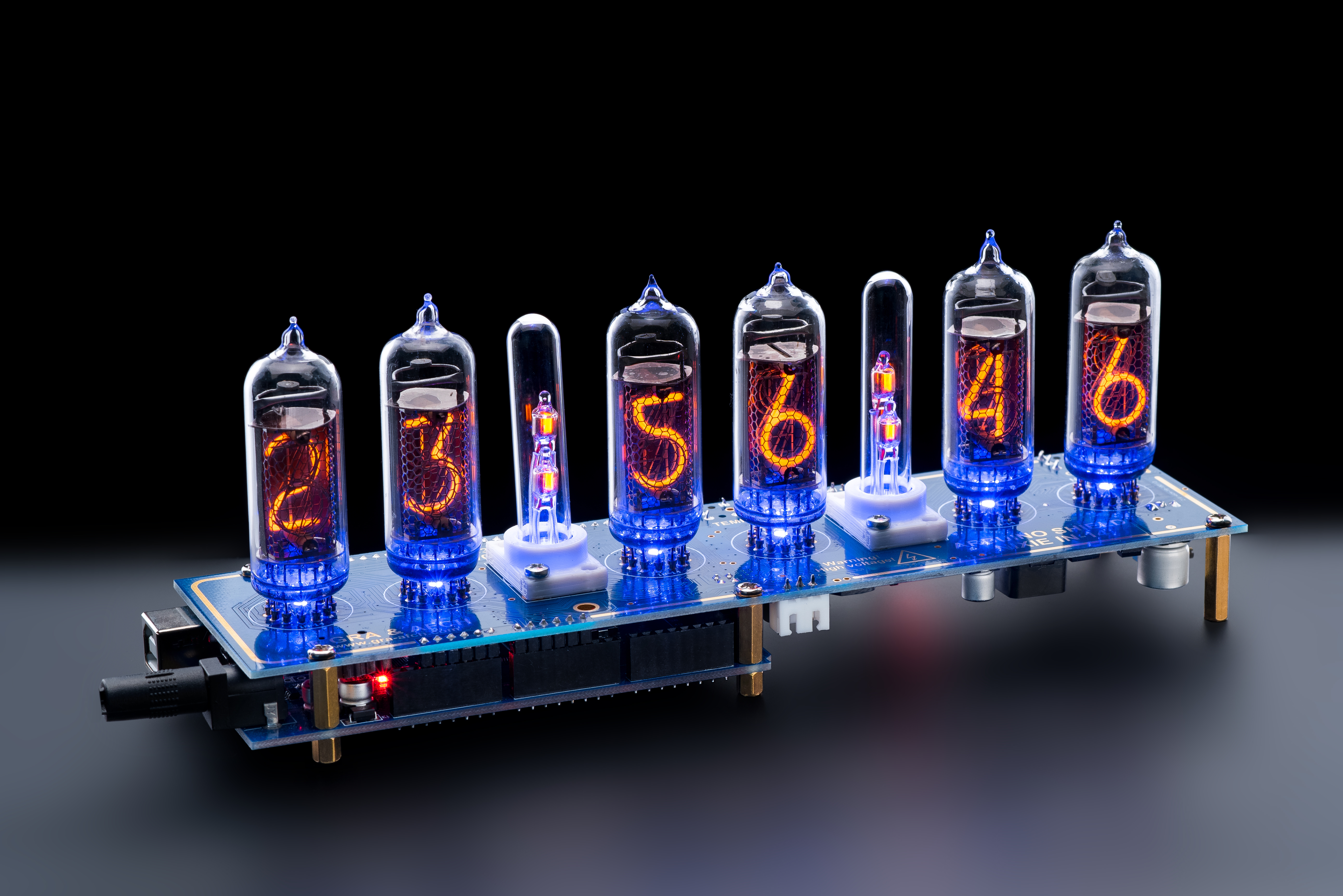
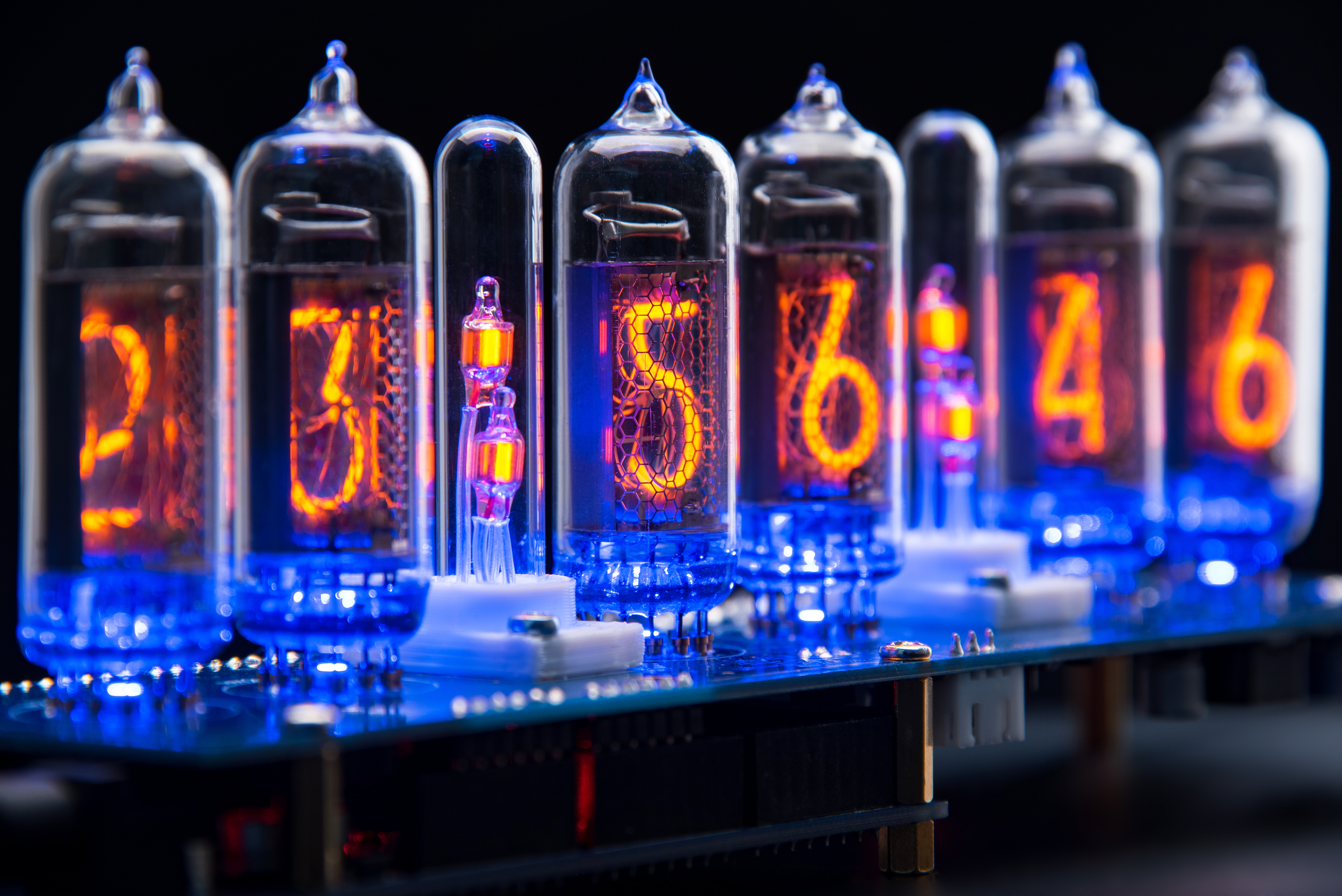
The next day, began to discuss the concept of the future project: to simplify and reduce the cost, it was decided to use the scheme with a dynamic display principle, but later it was decided to abandon it in favor of the scheme with a fully static display mode. Although for IN-14 Nixie tubes visual difference is not noticeable, but for the IN-18 lamps difference is noticeable - in dynamic mode, they work not so bright many of them appears, so-called, blue spots effect:
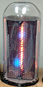
Dynamic display mode is a mode in which at each time are not all tubes are lit, and only one (at a time), may also be other species when illuminated simultaneously, for example, only two lamps.
In discussing the future of the device once it has been decided to implement the ability to display information on the tubes coming from the computer, it will allow enthusiasts to create their own device that would be displayed on the lamps, for example, the number of unread messages or the number of rounds in the game, such as Fallout.
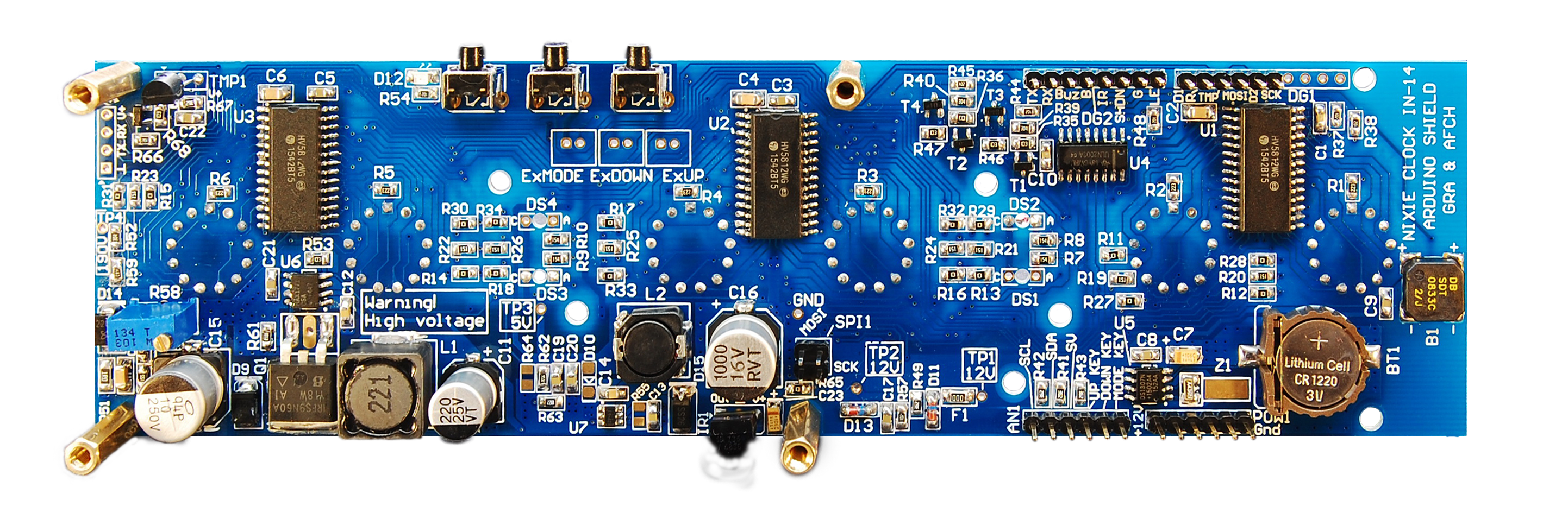
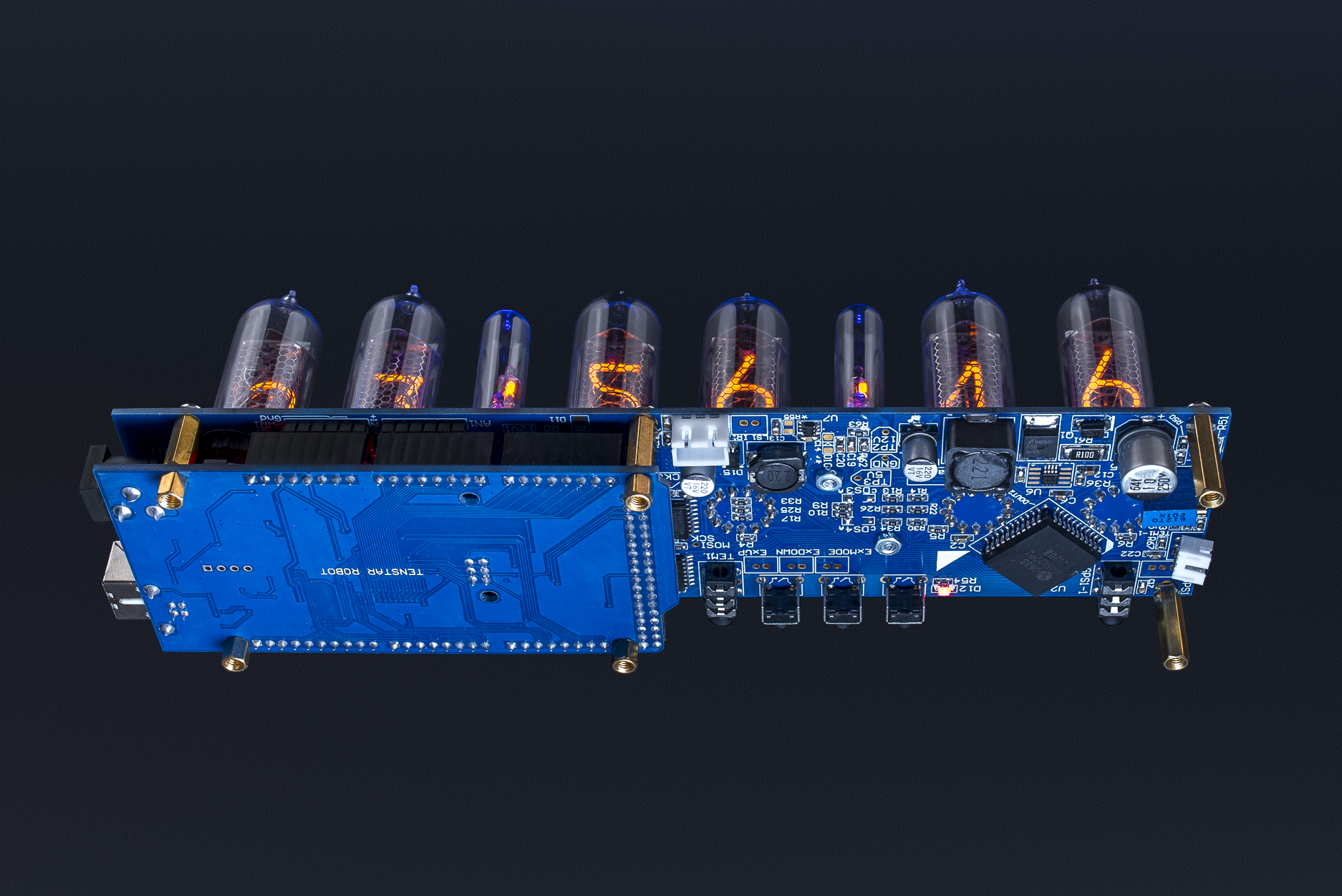
Then began the selection of hardware which could be switch cathodes (numbers) in the tubes. The choice was obvious - the shift registers with SPI to save MCU pins. But as the supply voltage tubesis very high - up to 200 volts, the options are not so much: HV513, HV5812, HV5122. And while we build the device on each of these chips, we stopped at the HV5812 (In the new Shields version NCS314 V2.X and NCS312 V1.X used IC HV5122). This chip is very convenient because it allows you to simultaneously control two lamps, as a 20 bit register.
To control 6 tubes we will need three such circuits are connected to each other in series. This allows once send packet over SPI and don't care of updating the information on tubes, as would be the case with a dynamic display algorithm. That is, in other words - as long as we do not need to change the information on the tubes MCU may be busy with other tasks, even sleep!
We would like to say about the transfer of data on SPI. Arudino can transmit at a time, only 8 bits. And we need 60, the nearest higher whole number is divisible by 8 is 64, and therefore have to apply a bit magic - to form one big variable of type unsigned long long var64 bits for each register and pass 8 times 8 bits each time by shifting all bits inside the variable to the right:
 SPI.transfer(var64);

 SPI.transfer(var64>>48);

 SPI.transfer(var64>>40);

 SPI.transfer(var64>>32);

 SPI.transfer(var64>>24);

 SPI.transfer(var64>>16);

 SPI.transfer(var64>>8);

 SPI.transfer(iTmp);
Synchronous Epoch Fetching (DS3231 + Anti-Poisoning)
Nixie hardware doesn't know what time it is. The logic expects a secondary DS3231 RCT I2C Chip for pure UNIX Time tracking.
- The C++ software must grab the exact time, e.g.,
14:38:05. - It dynamically splits the integers mathematically across 6 separate Nixie Tubes!
- Catastrophic Hardware Error: Cathode Poisoning!
- If the first Nixie tube sits displaying
1(for14:00) for twenty Solid Hours, the physical metal inside the tube chemically degrades ("Poisons") and the un-used numbers die permanently! - The C++ Software Fix (Slot Machine Code):
// Every 10 minutes, execute a massive Anti-Poisoning cycle!
if (minute % 10 == 0 && second == 0) {
  for (int i=0; i < 50; i++) {
    // Spin ALL tubes violently through 0, 1, 2, 3.. 9 instantly!
    // This physically burns the rust off all 10 internal wire numbers!
    fireNixieSlotMachineSweep();
    delay(50);
  }
}
Those objectives that were set and struck implemented:
- Static display based on shift registers.
- Slote Machine (Ani poisoning)
- Provide the standard functions for the clock, the clock, date, time, alarm clock.
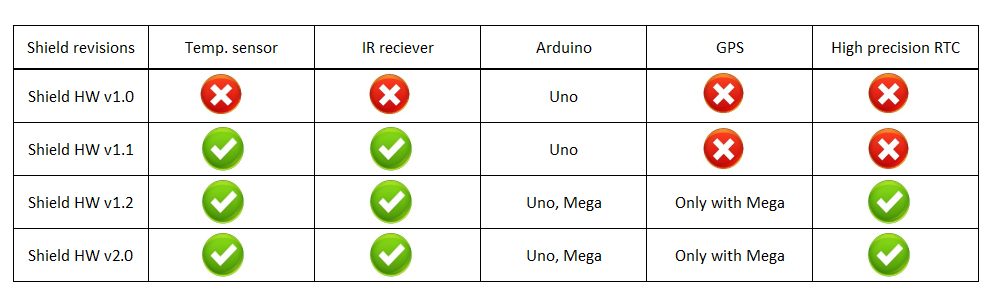
- RTC (Real Time Clock) with battery CR1220. (The new version of the V1.2-2.X board uses a High precision time chip RTC DS3231).
- Temperature measurement DS18B20 [Celsius or Fahrenheit].
- Control via the IR port TSOP4836 (Work only Mega). Checked with Remote control Sony RM-X151, But it is possible and other remote with a frequency of 36kHz.
- Time Synchronization with external GPS (Work only Mega)
- Easy menu.
- Separate management of the colon (the lower and upper point)
- RGB backlight colors with a smooth transfusion
- RTTTL ringtone for the alarm (Ring Tone Transfer Language)
- Slot machine (to prevent poisoning indicators)
- On self-test. (Check all numbers in each display from 0 to 9, to check all the LEDs, a serial switch colors blue, red, green, sound check (ring tones playing)
Those tasks that could not be realized fully.
- Light sensor
Legacy Voltage Equipment
- Arduino Uno/Nano (Standard execution speeds are perfectly sufficient).
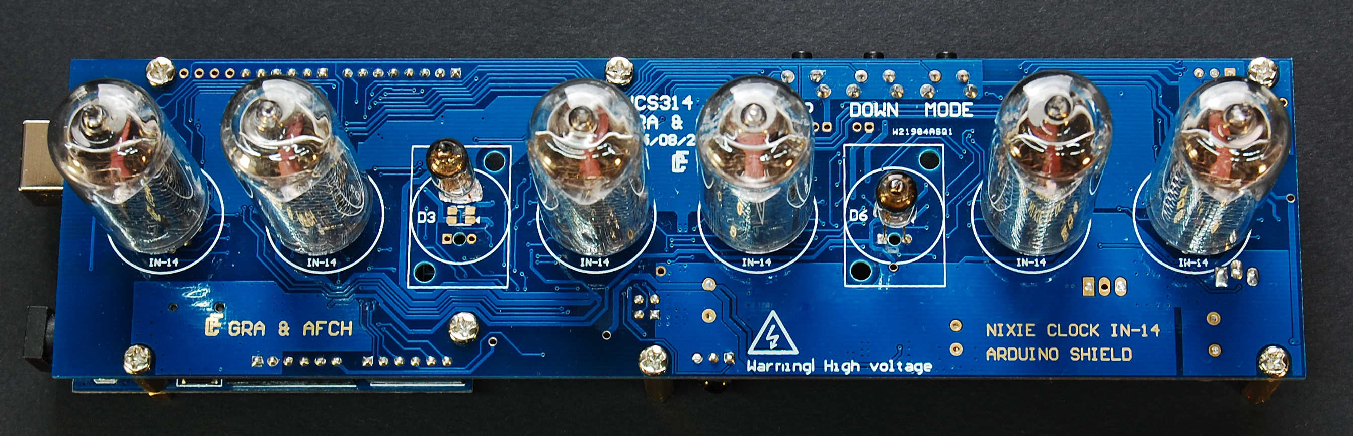
- Physical IN-14 or IN-12 Nixie Tubes (Vintage hardware sourced explicitly from Eastern Europe).
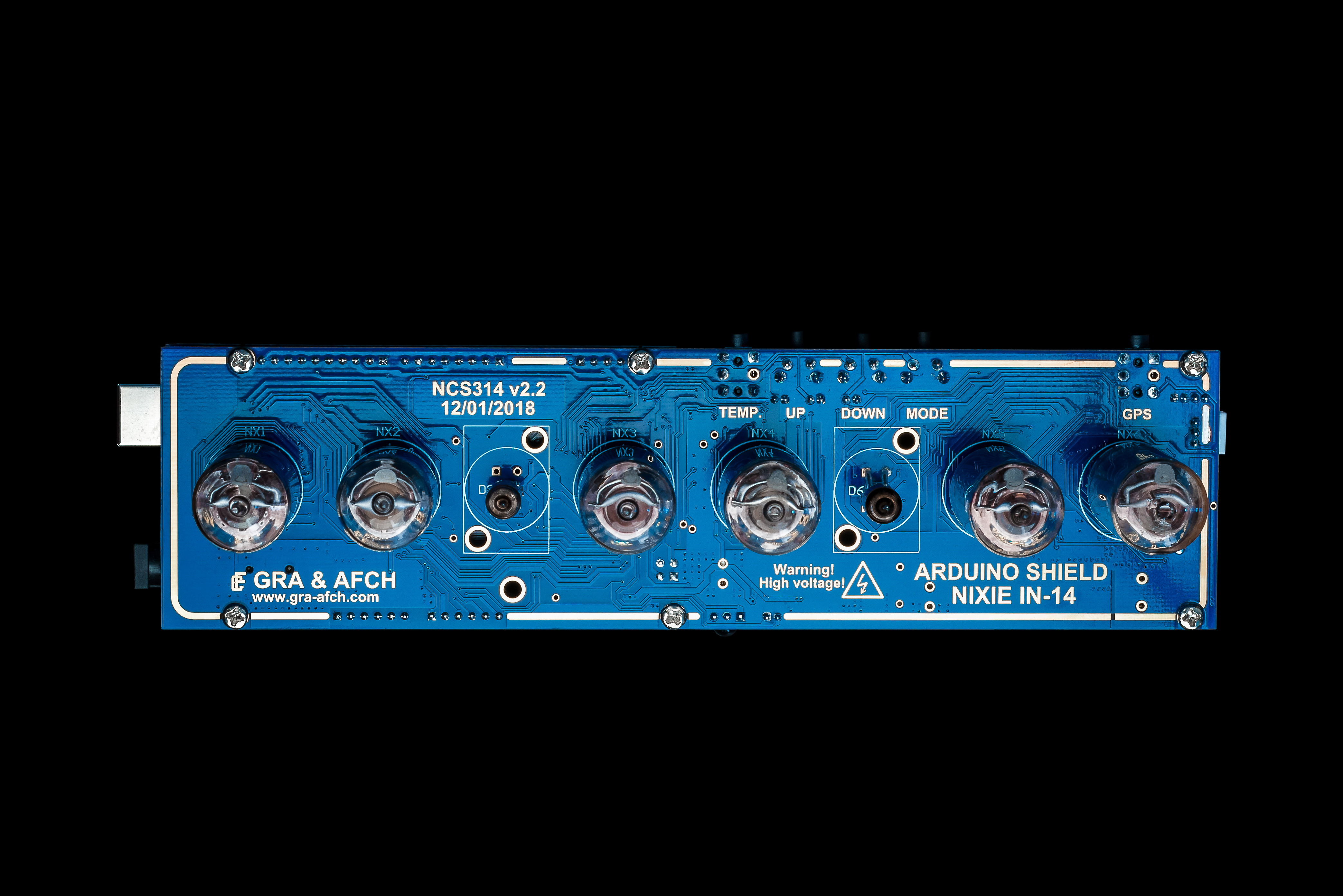
- NCS314 Nixie Shield or standard K155ID1 Decoder Matrices.
- DS3231 I2C Real Time Clock Module.
- (DANGER: 170 Volts DC will give you a horrific shock if you touch the bare traces on the PCB while trying to plug in the USB cable! Extreme caution required).