Description:
This project showcases an advanced timing system using two Arduino Nano microcontrollers to measure and record time. Designed for applications requiring precise time interval recording, this system stands out for its innovative use of I2C and SPI communications.
Functioning and Configuration:
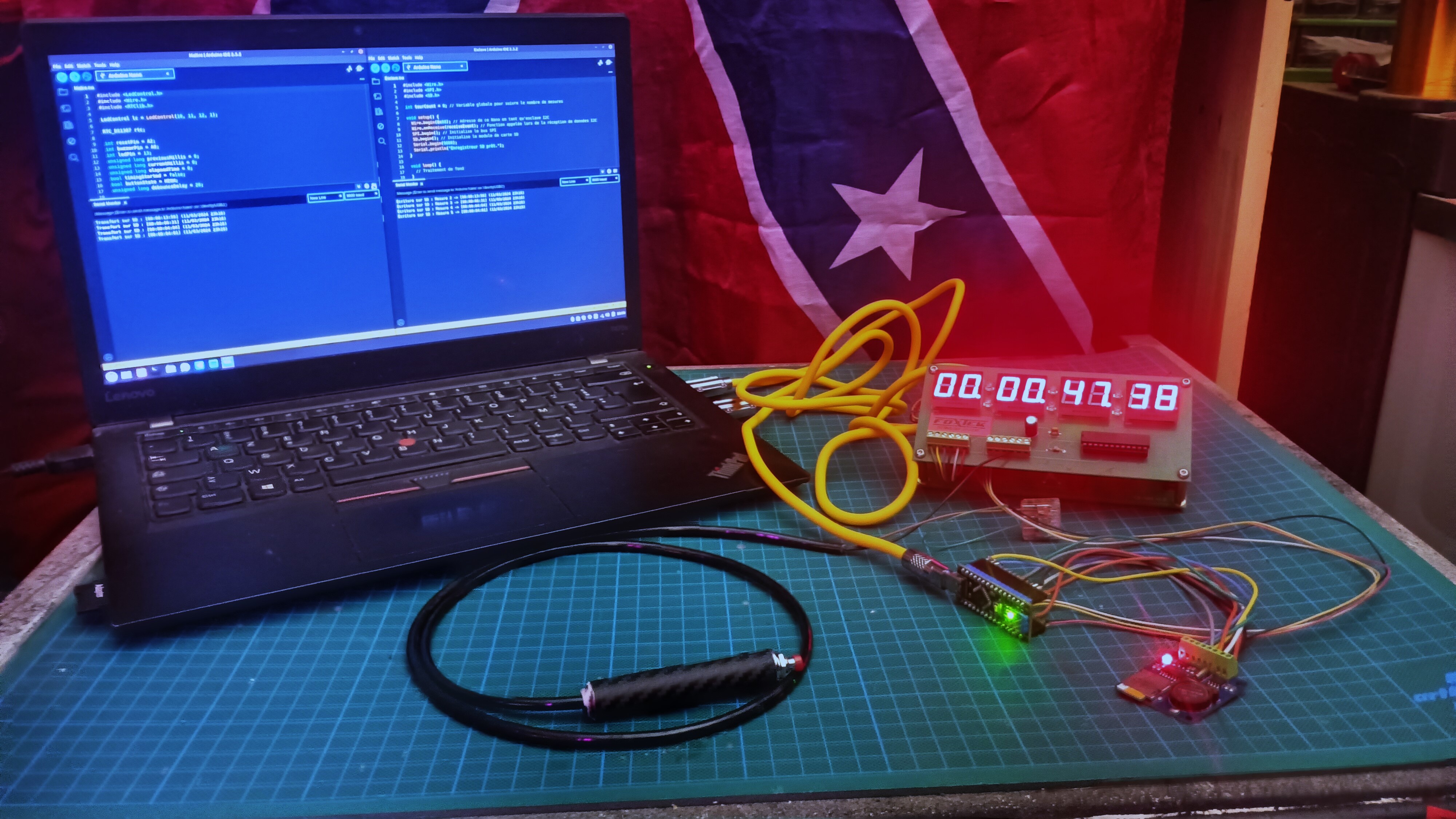
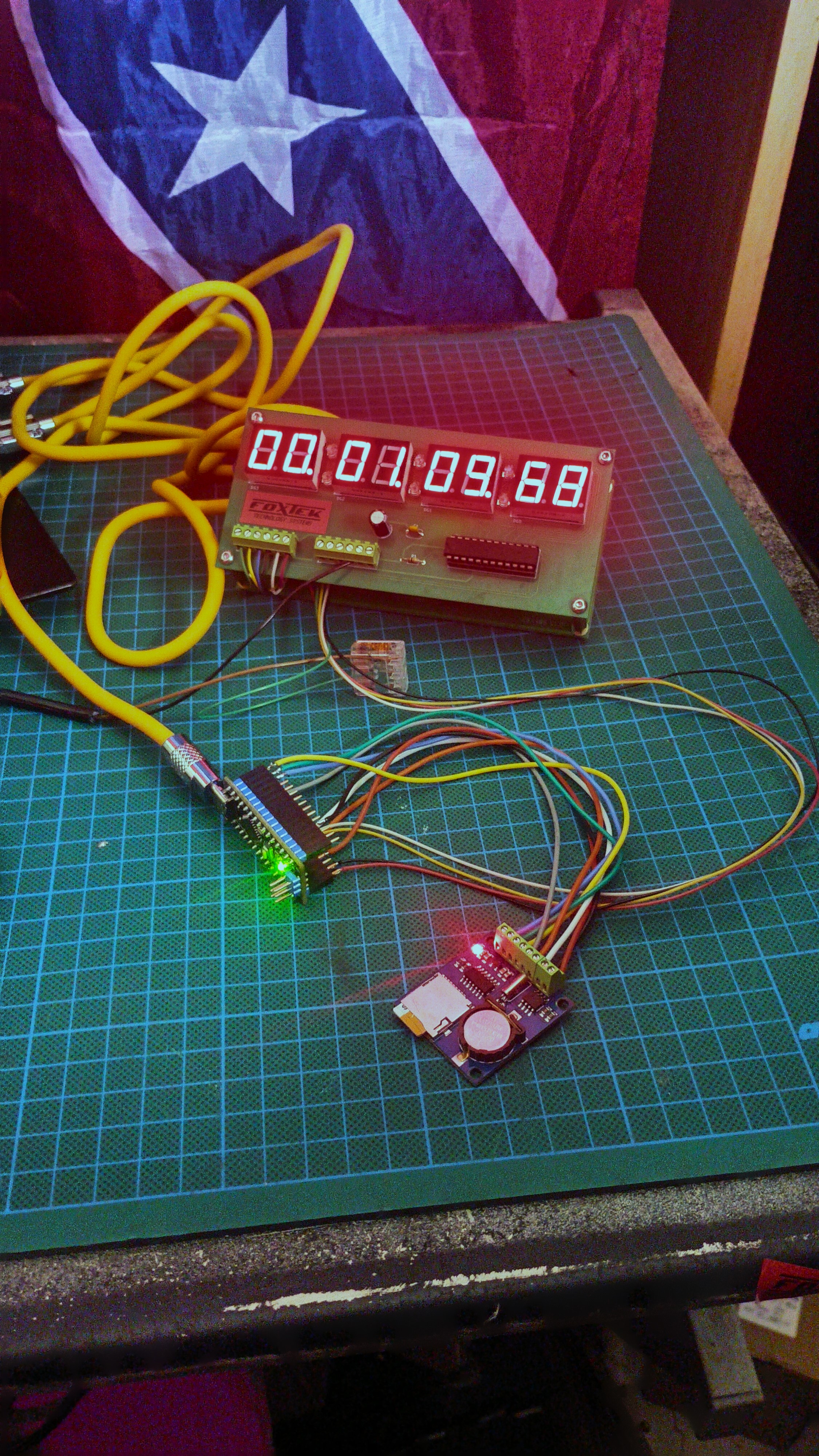
Master Unit: One Arduino Nano operates as the master timing unit. It's responsible for time measurement using a MAX7219 LED display, providing clear and instant readability of time measurements.
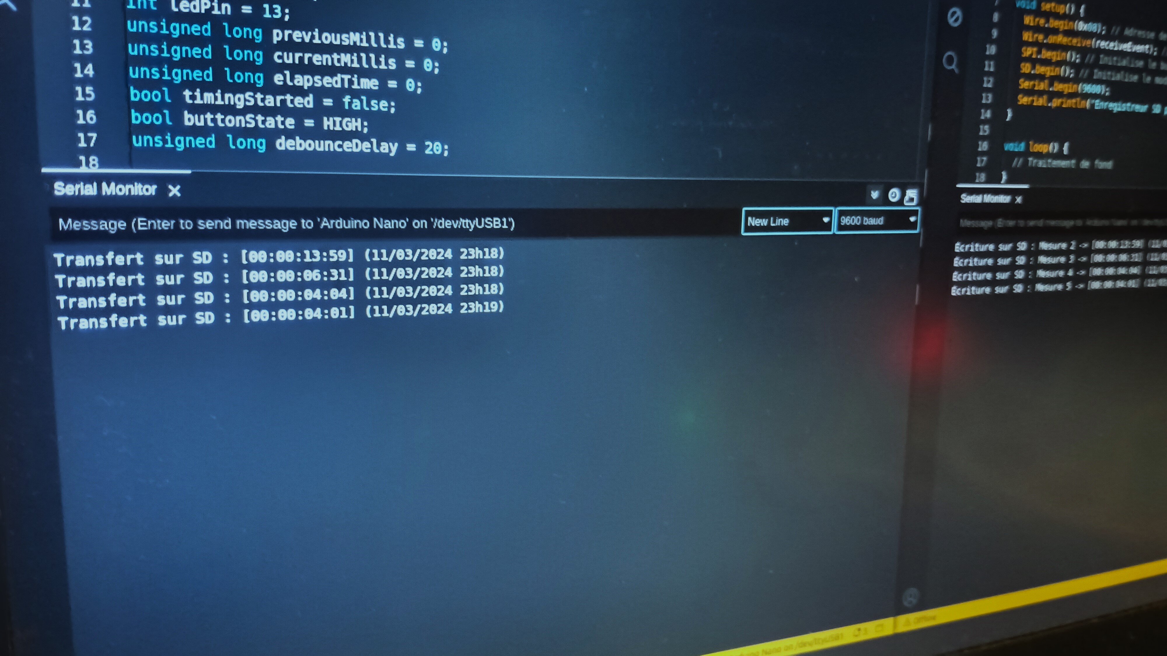
EXPANDED TECHNICAL DETAILS: The core of the timing logic on the master unit is the millis() function. Using delay() is avoided as it blocks the processor. Instead, the code captures timestamps: when the start button is pressed, it records startTime = millis();. Every loop, it calculates elapsedTime = millis() - startTime;. The complex part is formatting this value (e.g., 125430 milliseconds) into a human-readable display like 02:05.43 (Minutes:Seconds.Hundredths) on the MAX7219 display, which involves modulo and division operations.
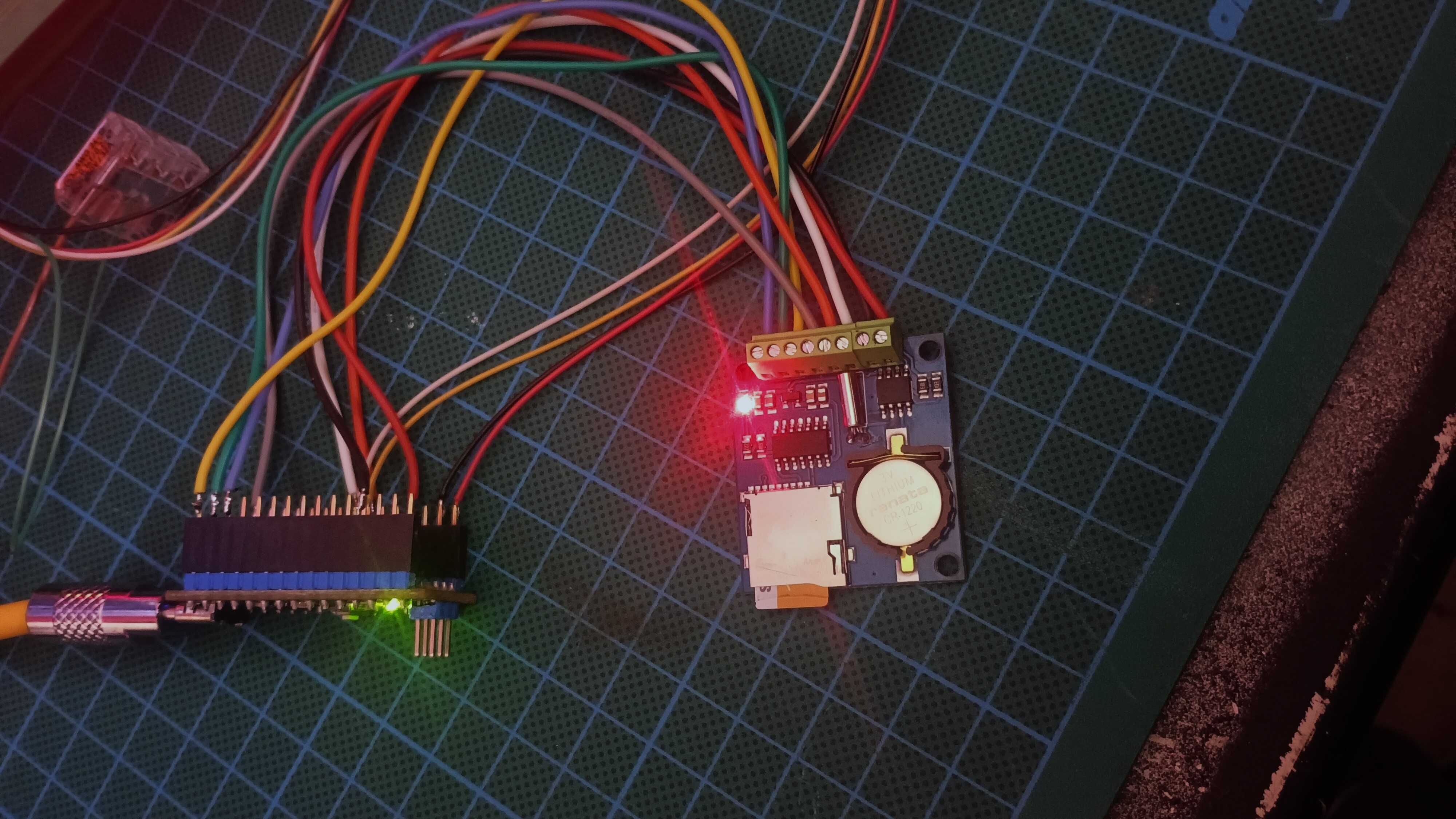
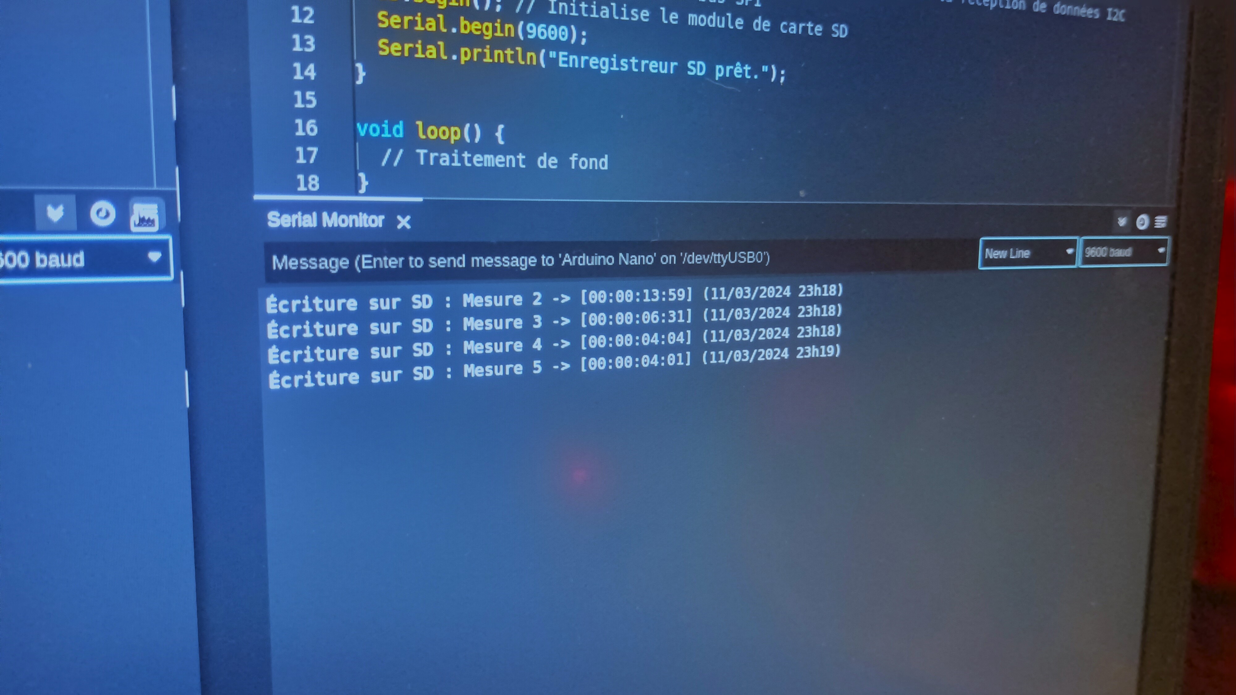
Slave Unit: The second Arduino Nano acts as a slave unit. Upon each reset of the stopwatch by the master unit, it receives the time data via I2C communication.
Data Recording: The slave unit records each time measurement, along with the date and time from a DS1307 RTC module, onto a micro SD card via SPI. Data is stored in a .txt file, and readable on most computers.
EXPANDED TECHNICAL DETAILS: Adding Lap Functionality
A key feature that can be implemented is lap timing. When a "Lap" button is pressed on the master unit, the current elapsedTime can be saved into an array (e.g., laps[lap_count] = elapsedTime) and transmitted via I2C to the slave. The slave unit can then record this lap time along with the final time, providing detailed breakdowns for each recorded event.
Technologies Involved:
I2C Communication: Used for transmitting time data between the two Arduino Nanos.
SPI Communication: Employed for writing data to the micro SD card.
RTC DS1307: Provides a precise time reference for recording measurements.
Hardware Components:
- Arduino Nano (x2): The master clock and the slave recorder.
- MAX7219 LED Display Module: For clear time display on the master unit.
- 16x2 Text LCD with I2C (conceptual alternative): Could be used as a display in simpler versions.
- Push Buttons: For Start/Stop, Lap, and Reset control.
- Pull-down Resistors (10k-ohm): For stable button input.
- Micro SD Card Module: For data logging on the slave unit.
- DS1307 RTC Module: For accurate timestamping.
Applications:
The system is ideal for educational environments, DIY projects, and applications requiring precise time documentation, such as scientific studies, performance testing, or activity tracking. This project is the foundational code required if you ever want to build a track-timer using lasers to measure the exact speed of RC cars or athletes.
This project effectively demonstrates how to combine functionalities of different Arduino components to create a complex and functional device. It also serves as an excellent foundation for those looking to delve deeper into inter-Arduino communication and data management.