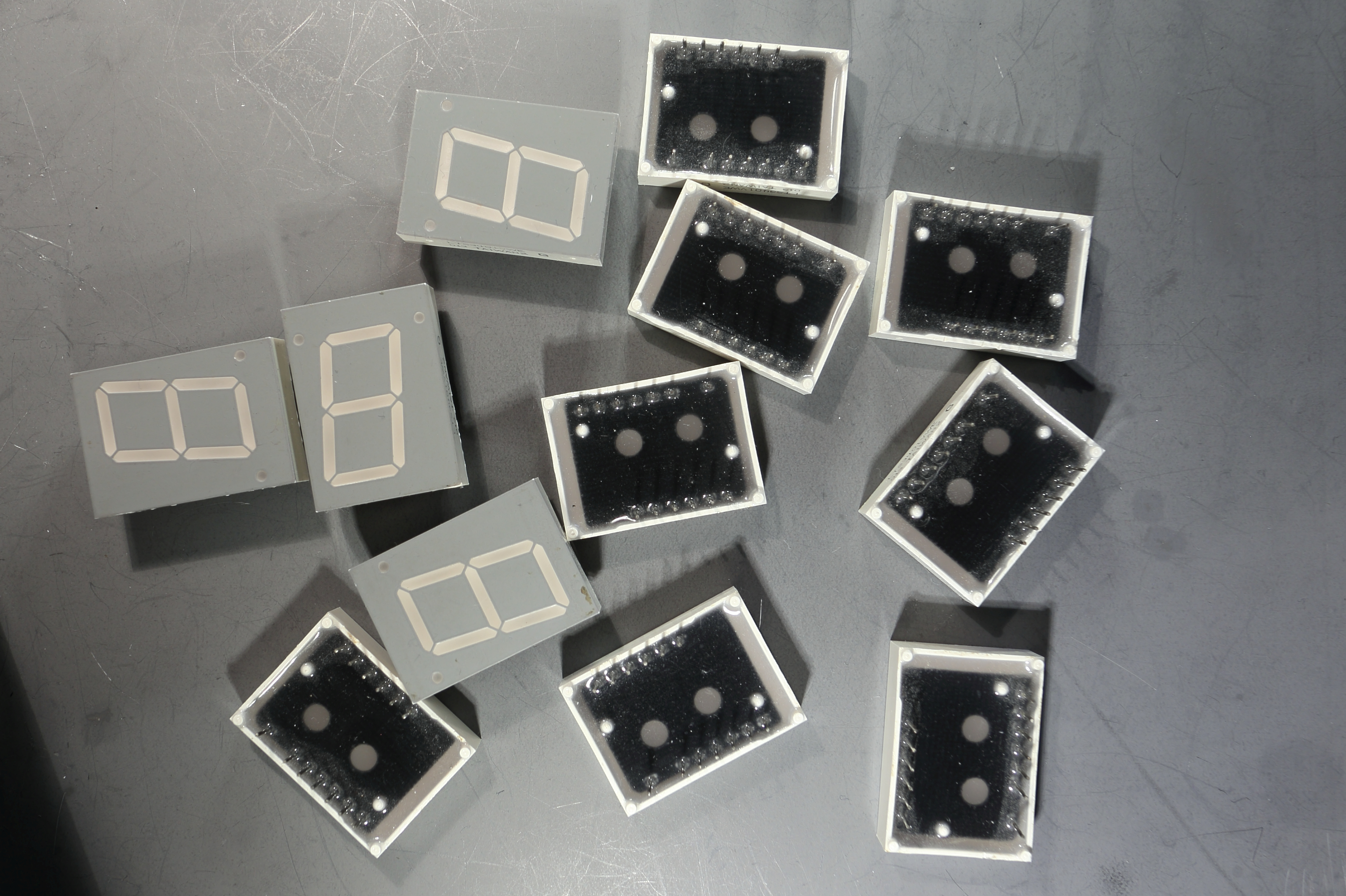
Years ago I ordered 12 7-segment displays. I wanted to make a clock that displayed the time and date. But it appeared that it took too much digital IC's to realize it. Nowadays there is arduino, and now it's much easier to do it.
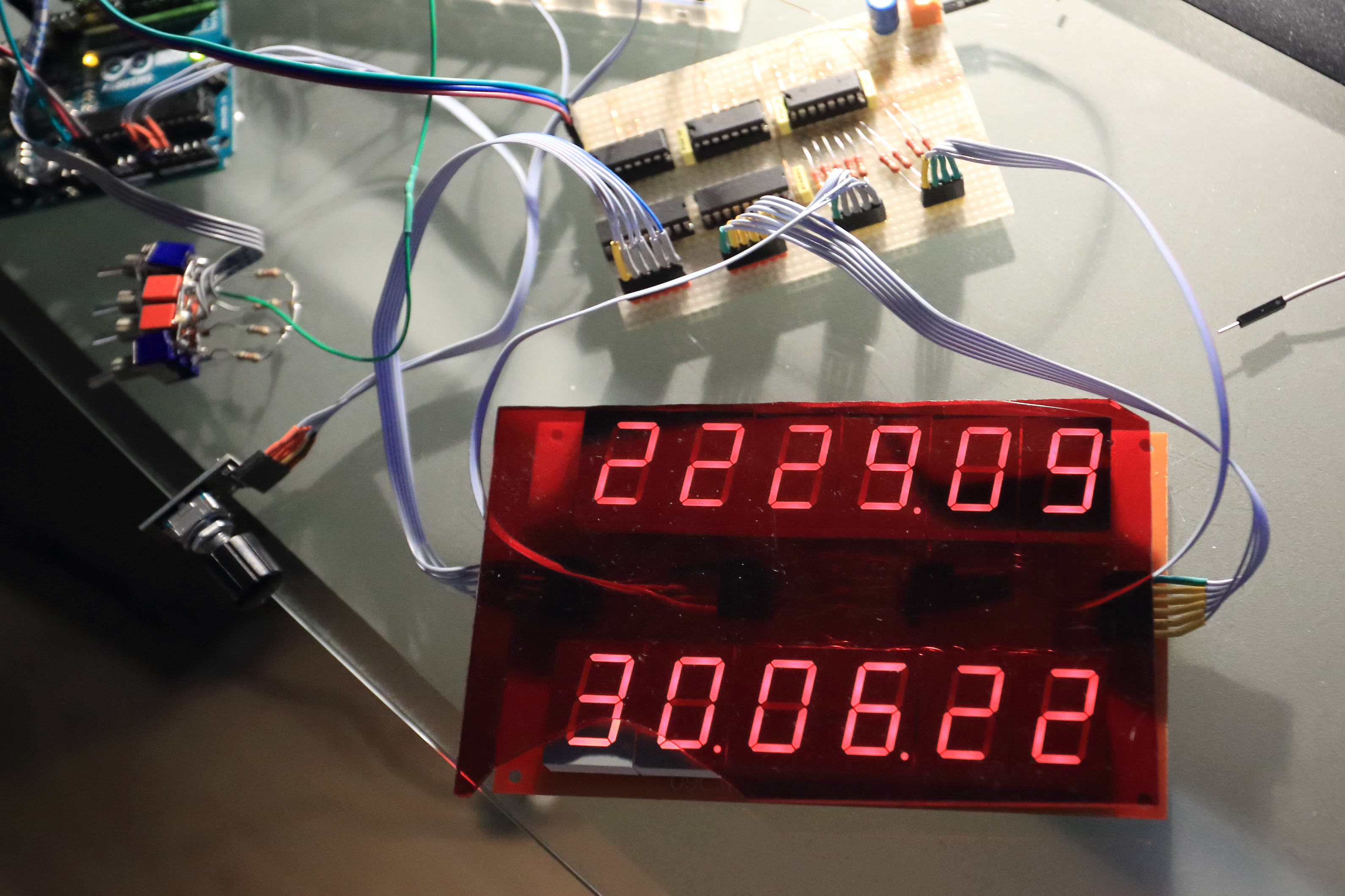
This clock can display time and date, moonage in days, sun rise and sun set, the maximum elevation of the sun, actual elevation of the sun, tilt of the earth, time between sun rise and sun set, air pressure in mBar, temperature in celsius, Adjust mode to set the time and date, and set the aging register of the RTC.
This clock is using the 1 Hz SQW from the RTC as an interrupt. I made my own routines for the RTC (DS3231) so there is no need to load a RTC library
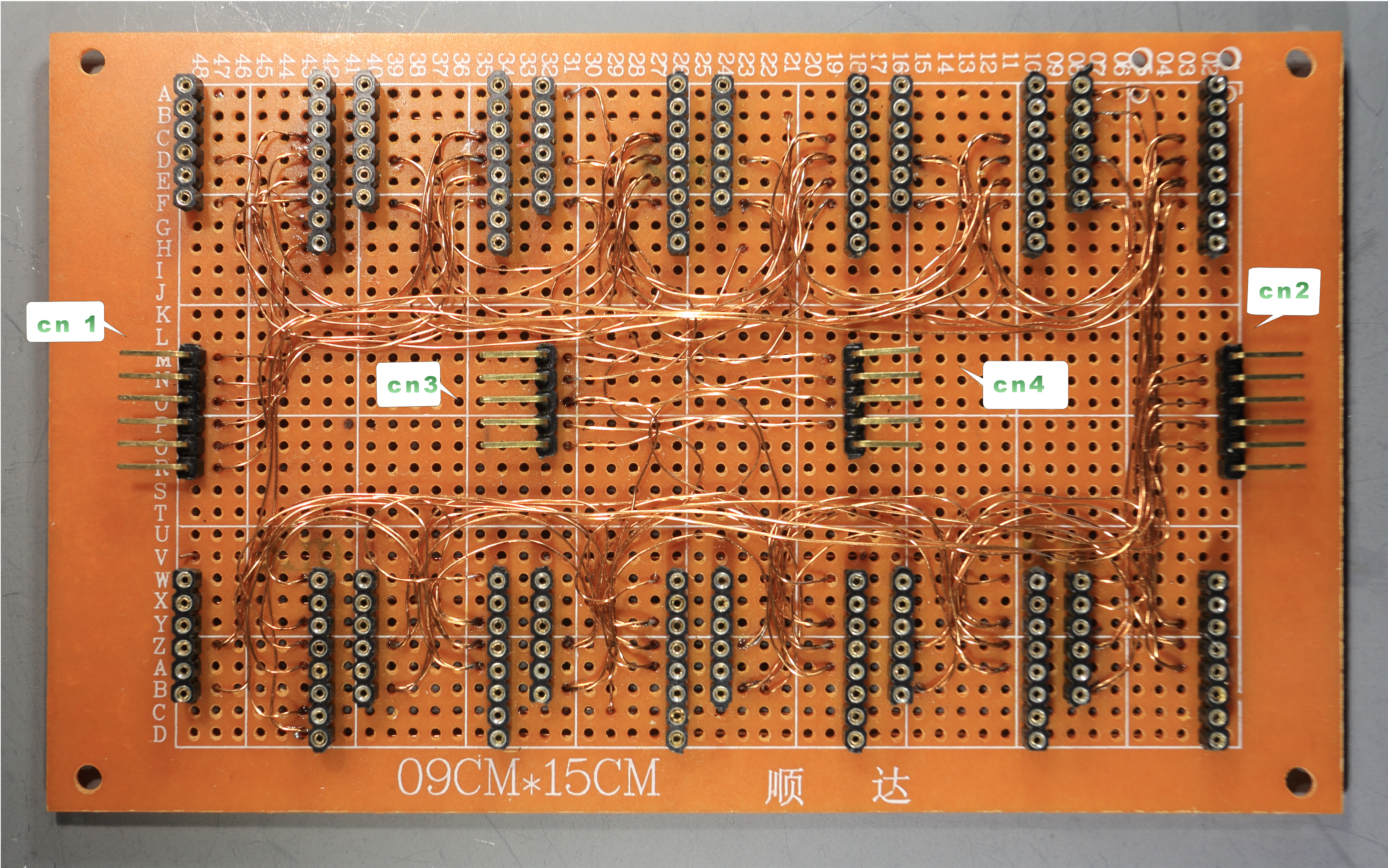
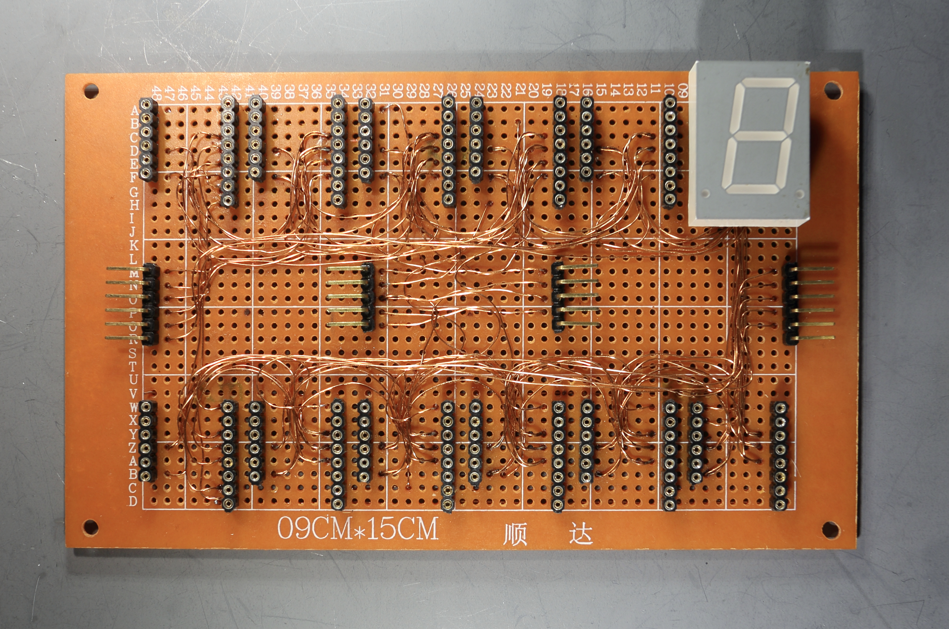
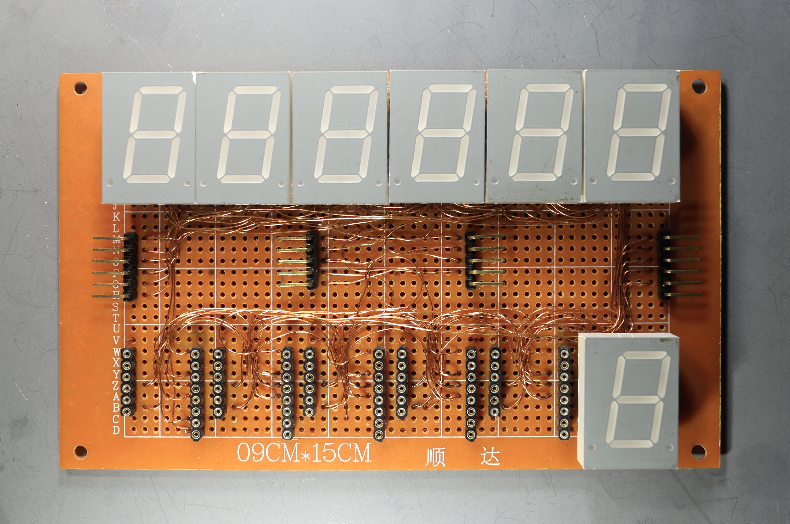
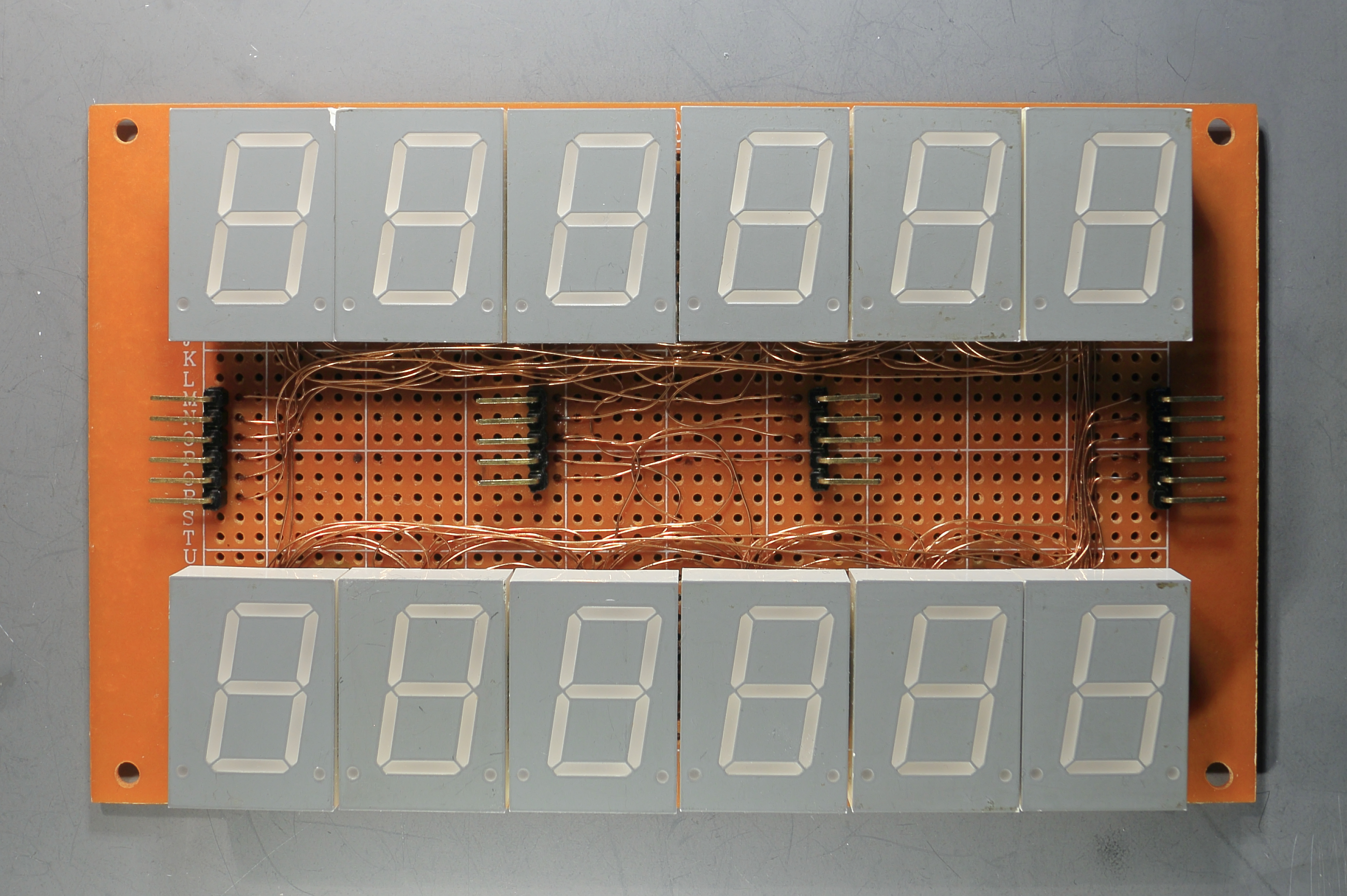
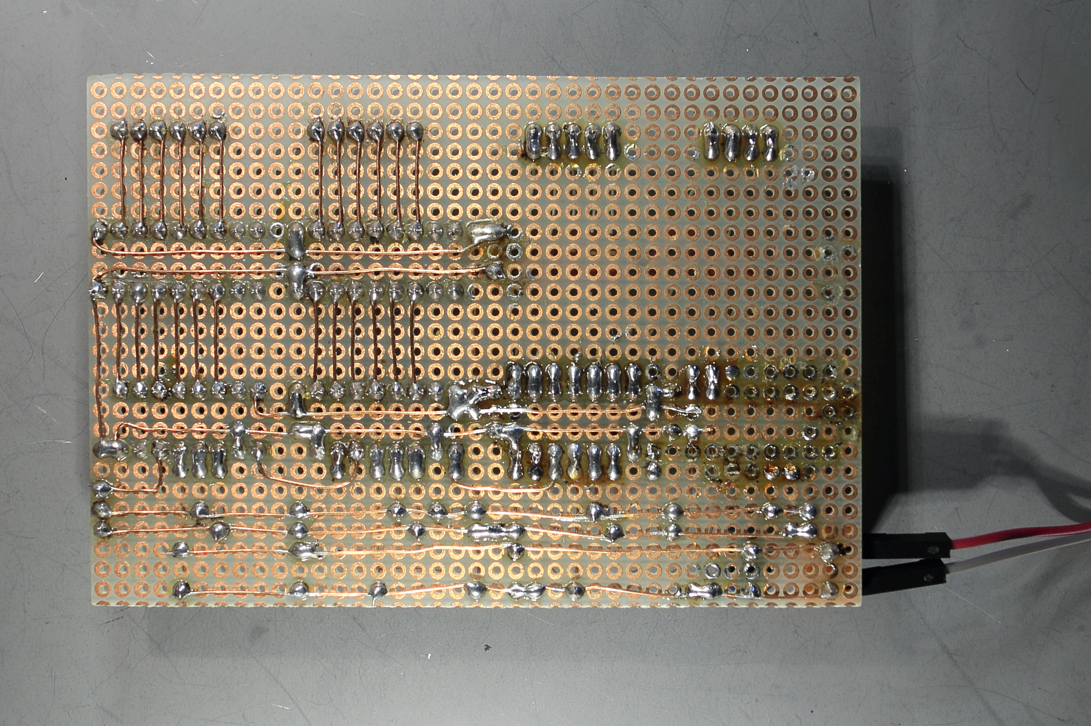
Because I am using multiplexing, the first thing I did was to connect al the a-segment of the 12 displays together. Also the b-segment, and c, d, e, f, g and dot segment. See photo of the displayboard

Then I made a little board for the three shift registers (SN74595)
I used resistors of 220 Ohm, because the segments current max is 20 mA
The current is (5-1.8)/220=14.5 mA. Because I was not sure how much the current was, I put two transistor drivers (UDN2981) to the CA (Common Anode) of each display. The maximum output current of the shiftregister is 35 mA. In theory when all the segments are lit the current should be 8*14.5 = 116 mA.
Way too much for the shiftregister, but in reality it will be less, because of the multiplexing.
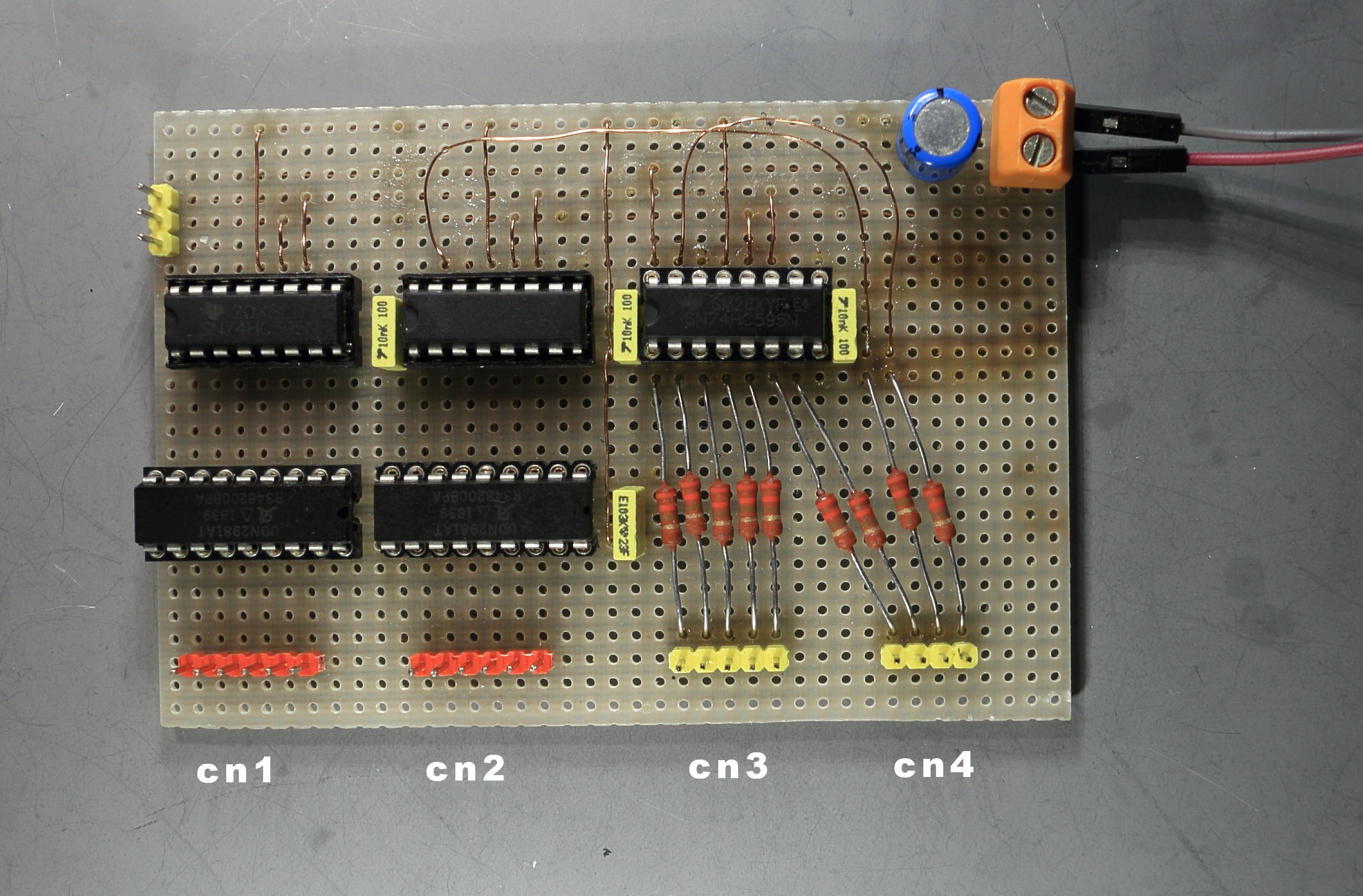
Board2- CN1 connects to CN1 of the display board. Left pin of the connector is the first upper display. Second pin is the second display etc..
Board2- CN2 connects to CN2 of the display board. Left pin of the connector is the first lower display. Second pin is the second display etc..
Board2- CN3 connects to CN3 of the display board. Left pin of the connector is the a-segment, second is the b-segment untill the e-segment
Board2- CN4 connects to CN4 of the display board. Left pin of the connector is the f-segment, second is the g-segment, the right pin is the dot-segment
The program checks the state of the four switches (in the void loop)
In the loop the time will be updated once a second, once per 3 seconds the air pressure sensor is read.
Next video will show you the start up of the clock, and then shows the time and date.
With four switches there are 16 functions.
The 16 functions are as follows:
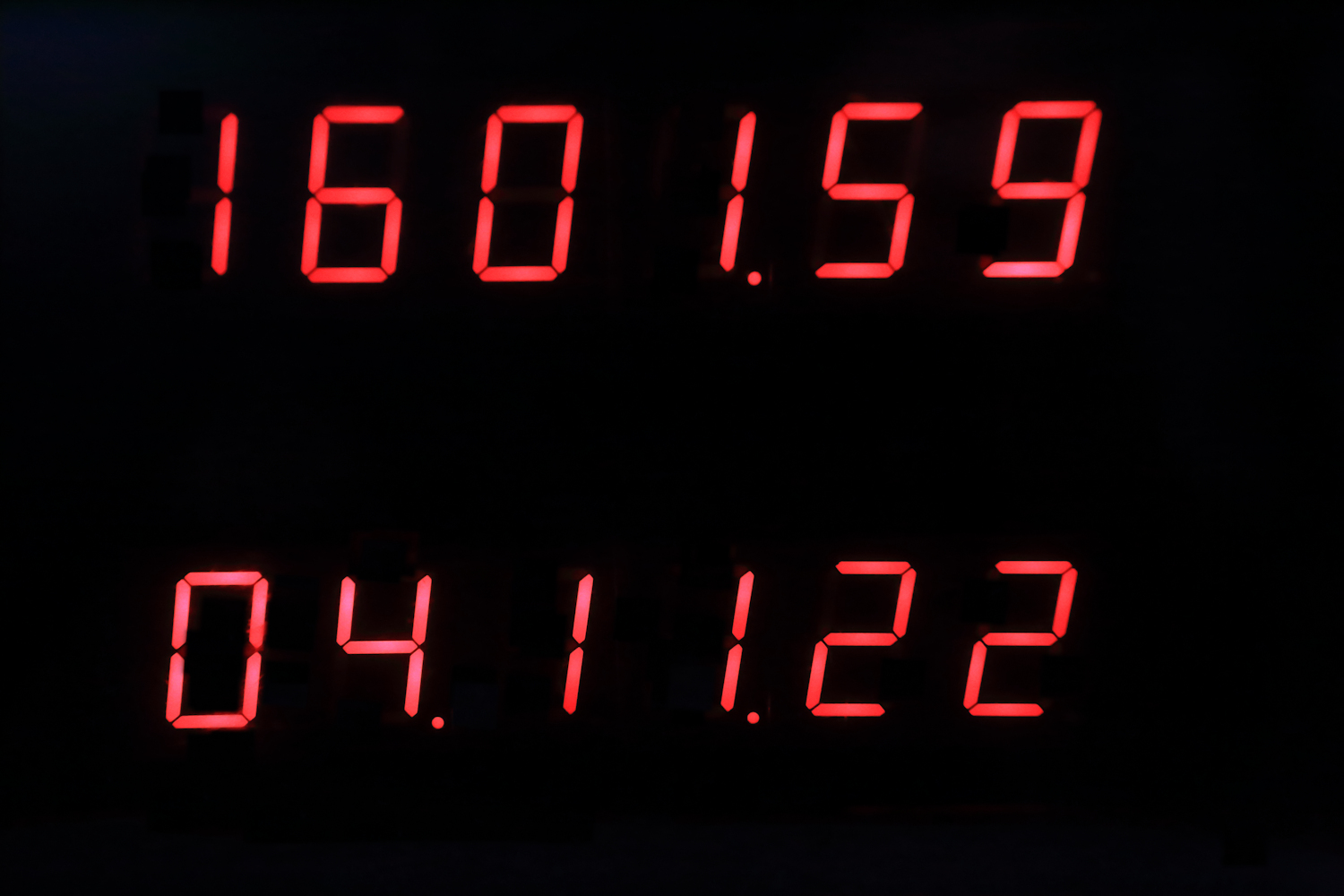
Switch position 0000
upper display: time
lower display: Date (day, month, year)
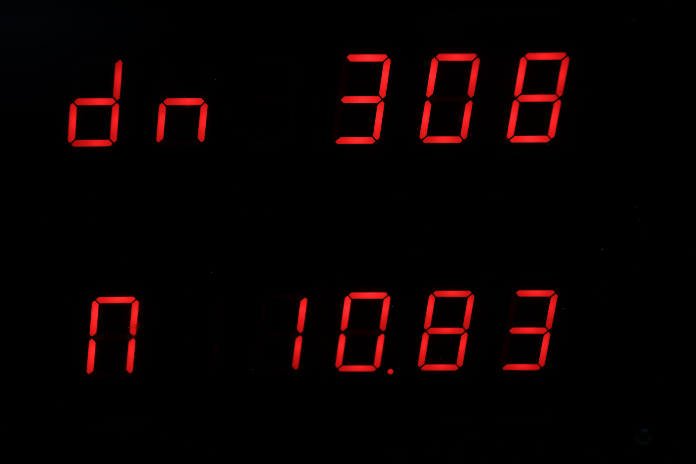
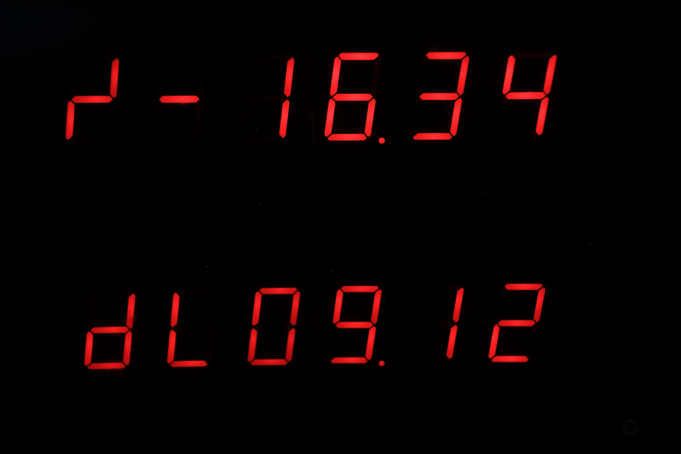
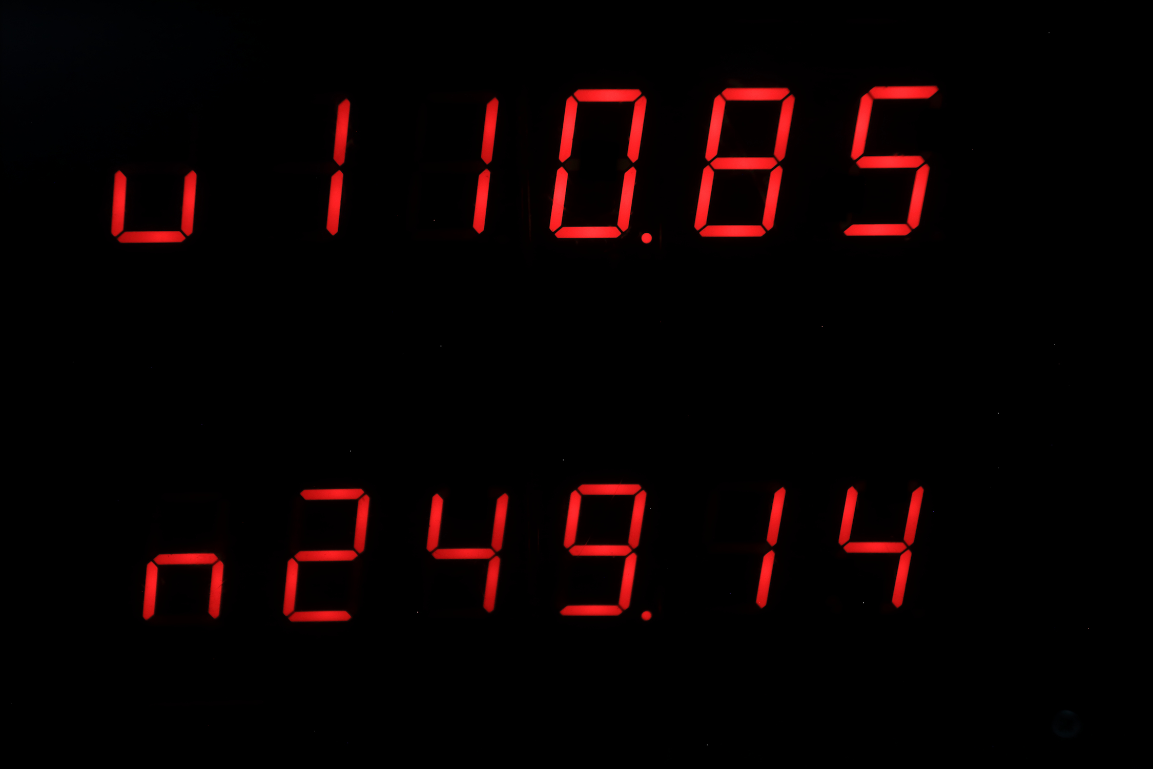
Switch position 0001
upper display: dn = (the amount of days since januari first)
lower display: n = moonage in days
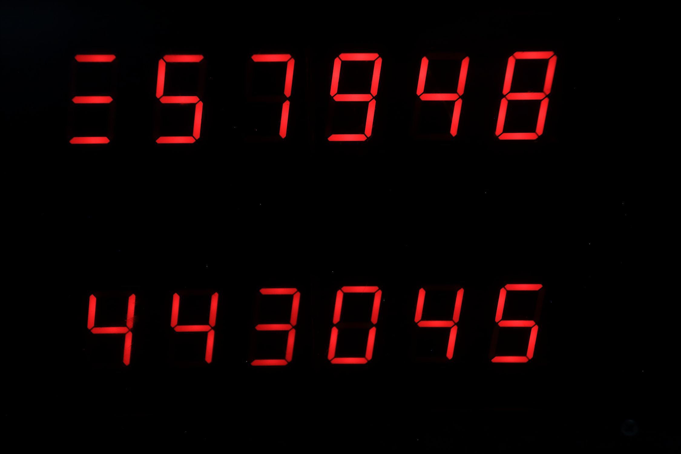
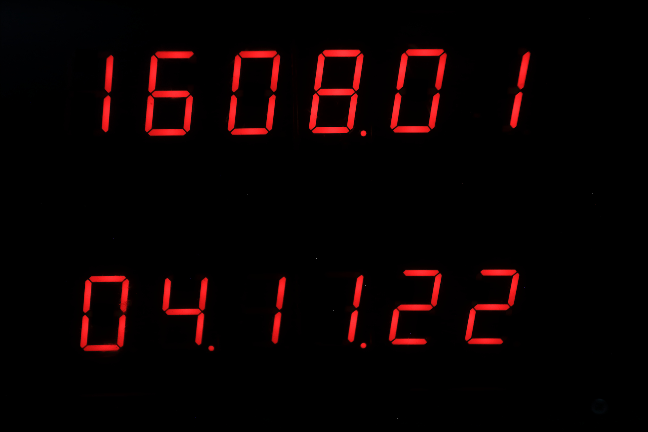
Switch position 0010
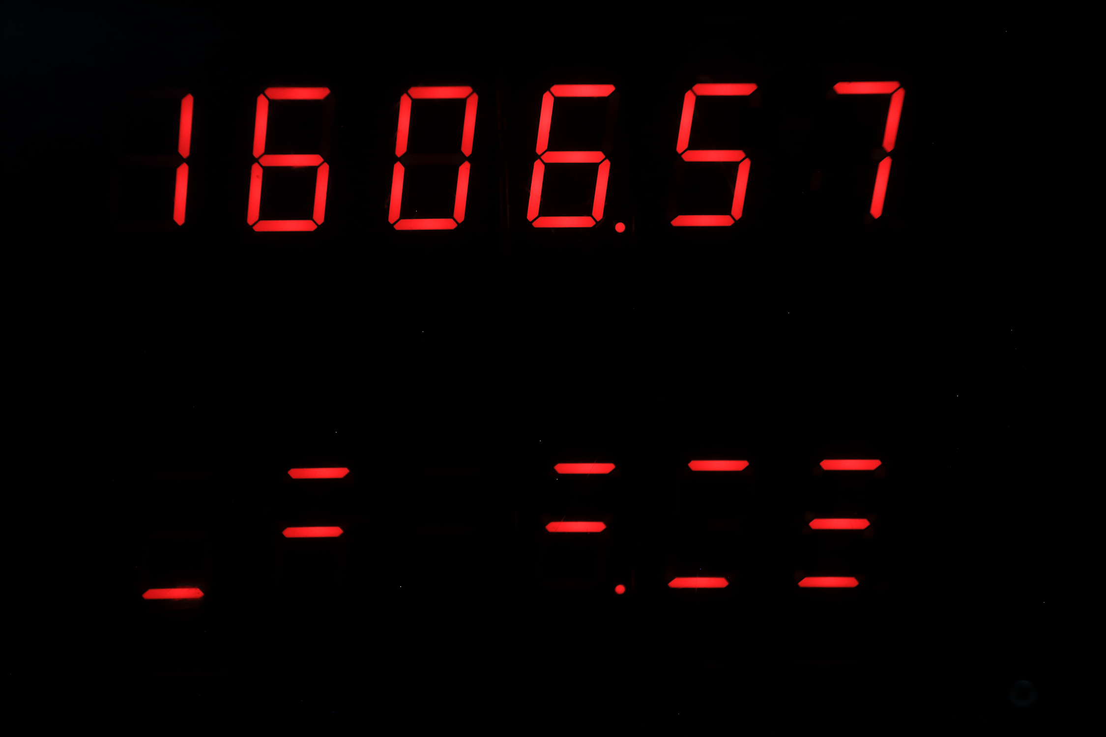
upper display: amount of seconds since midnight (max = 86400)
lower display: amount of minutes since januari first
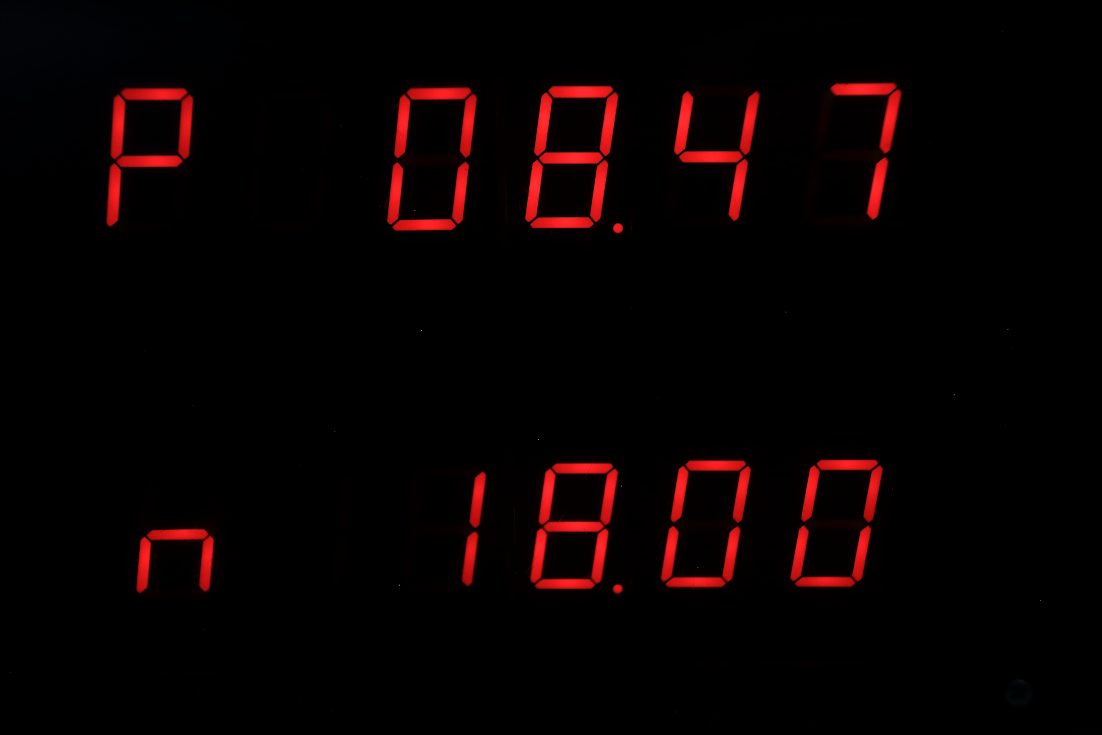
Switch position 0011
upper display: p = sun rise (depends on local latitude and longitude)
lower display: n = sun set
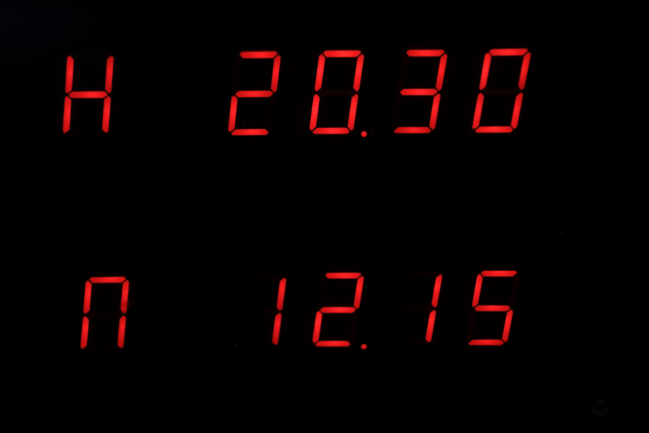
Switch position 0100
upper display: H = maximum elevation of the sun at noon in degrees.
lower display: n = actual elevation of the sun (will be zero at sunrise or sunset)
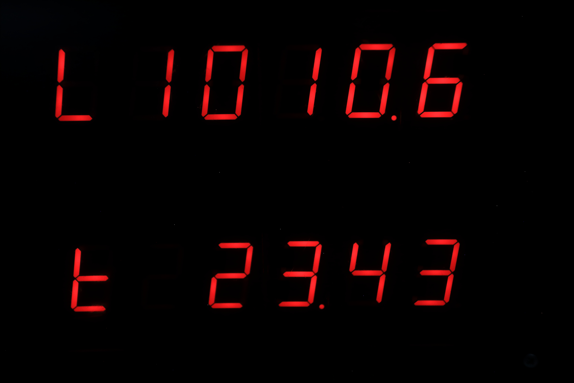
Switch position 0101
upper display: tilt of the earth in degrees(zero at start of spring and start of autumn, +23.5 at start of summer, -23.5 at start of winter)
lower display: dL = time between sun rise and sun set = daylight
Switch position 0110
upper display: L = air pressure in mBar
lower display: t = temperature in celsius
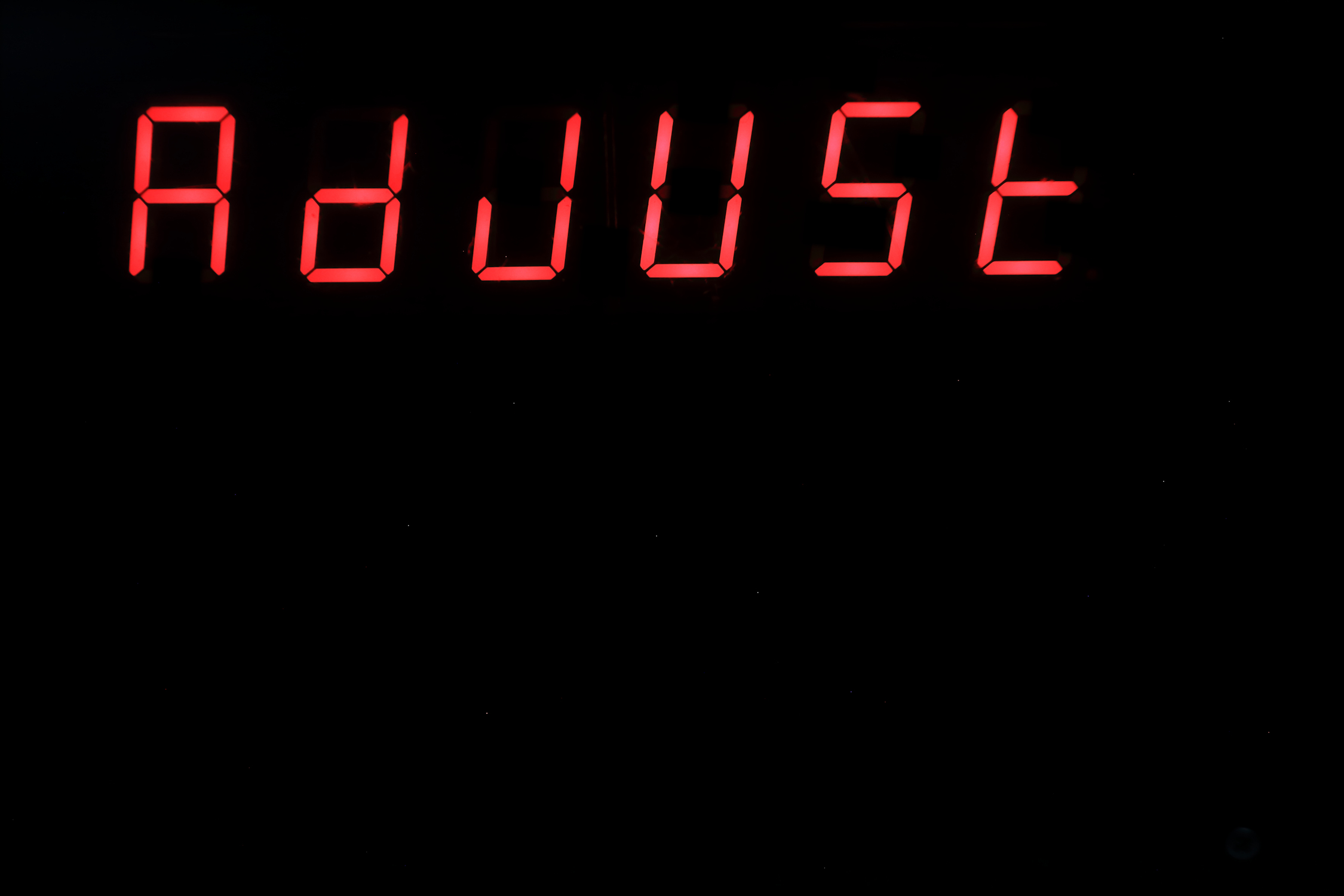
Switch position 0111
upper display: AdjUst
lower display: blank
You can set time, date and aging register of the RTC, and you can set latitude and longitude.
Switch position 1000
upper display: time
lower display: time in a binary format (except number 8 and 9)
Switch position 1001
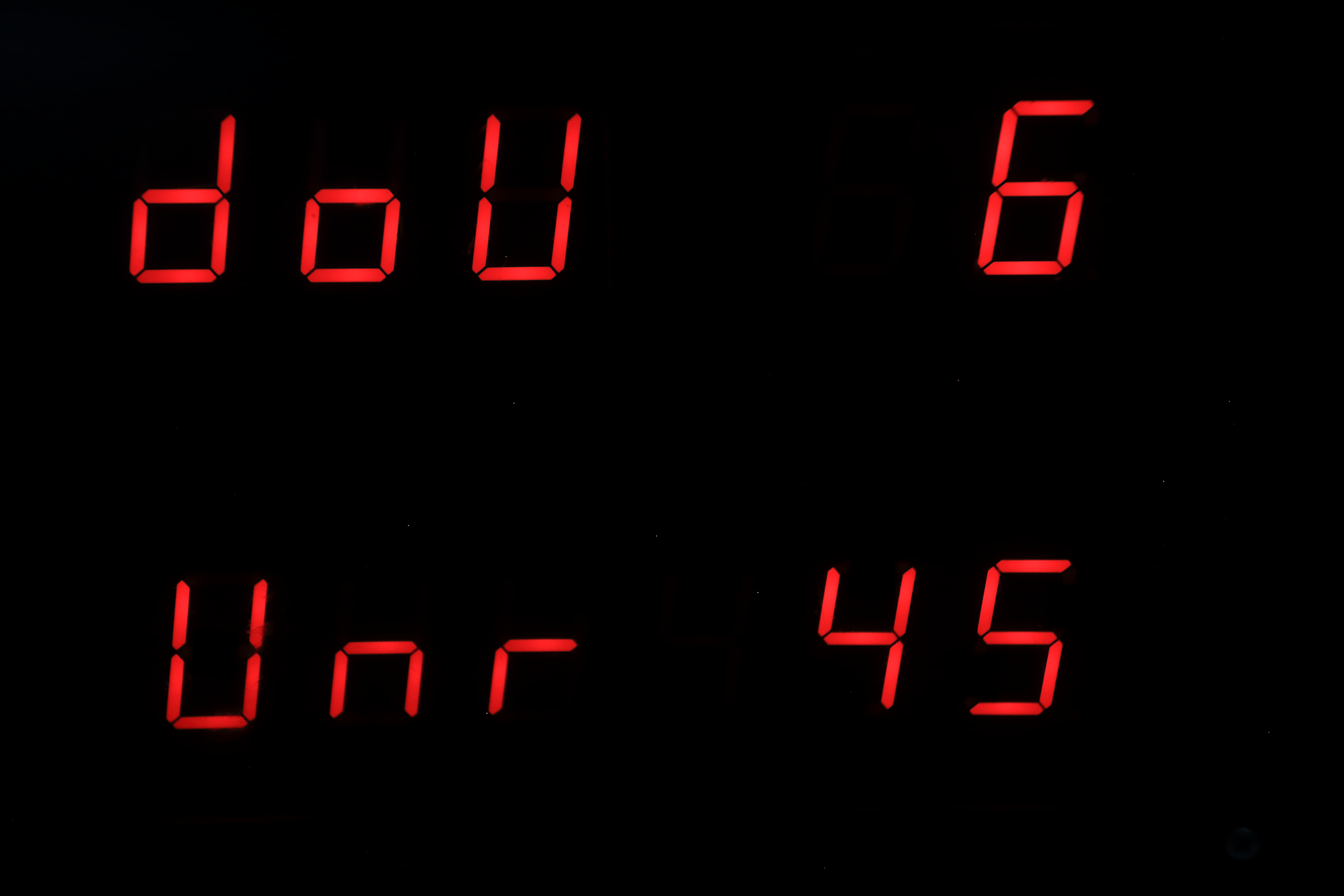
upper display: dow 6, The number of the day of week, 1 = sunday, 2 = monday etc...
lower display: unr 45, The week number
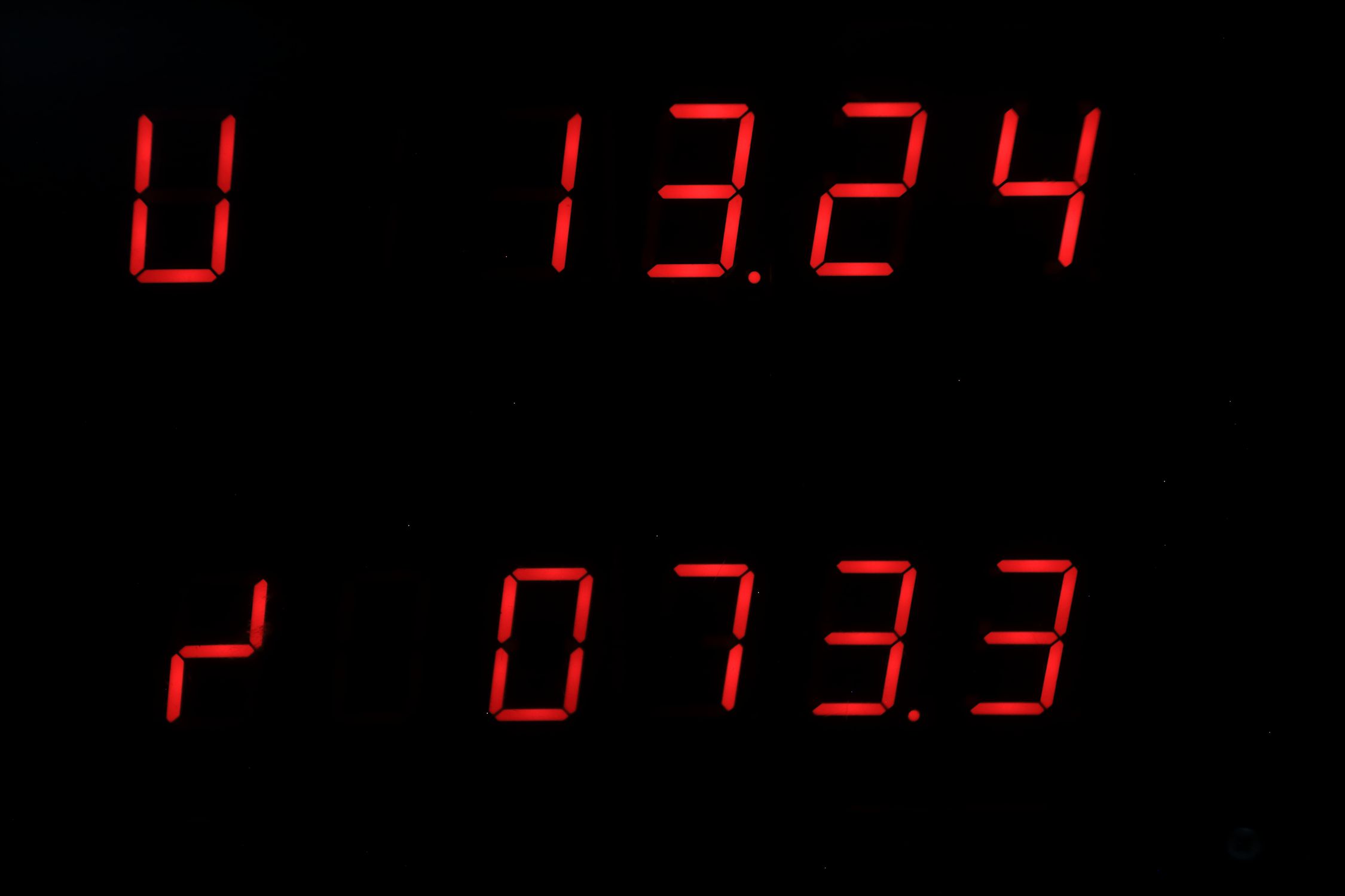
Switch position 1010
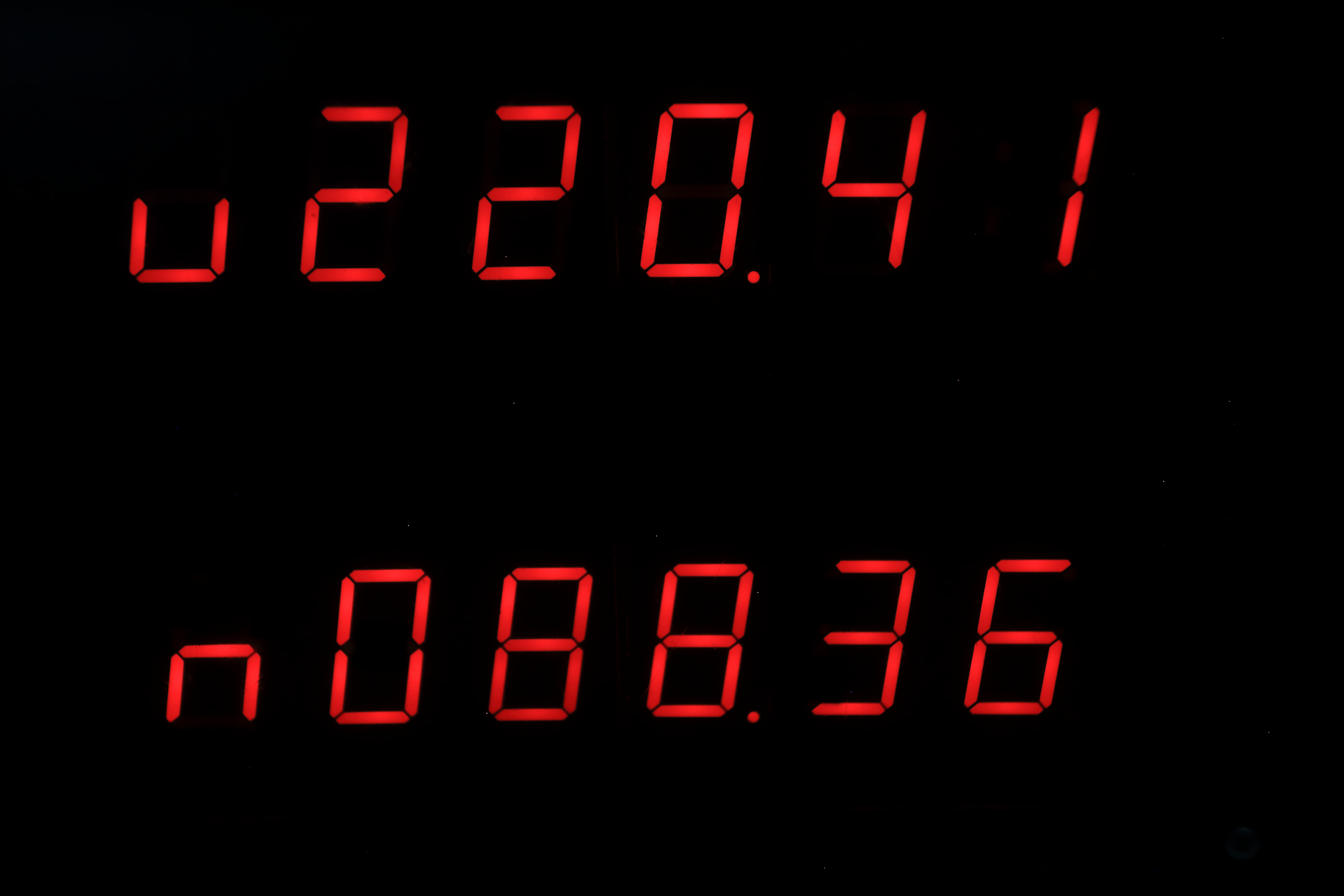
upper display : u = Azimuth earth in degrees.
lower display : n = Azimuth moon in degrees.
position on the horizon: 0 = north, 90 = east, 180 = south, 270 = west)
Switch position 1011
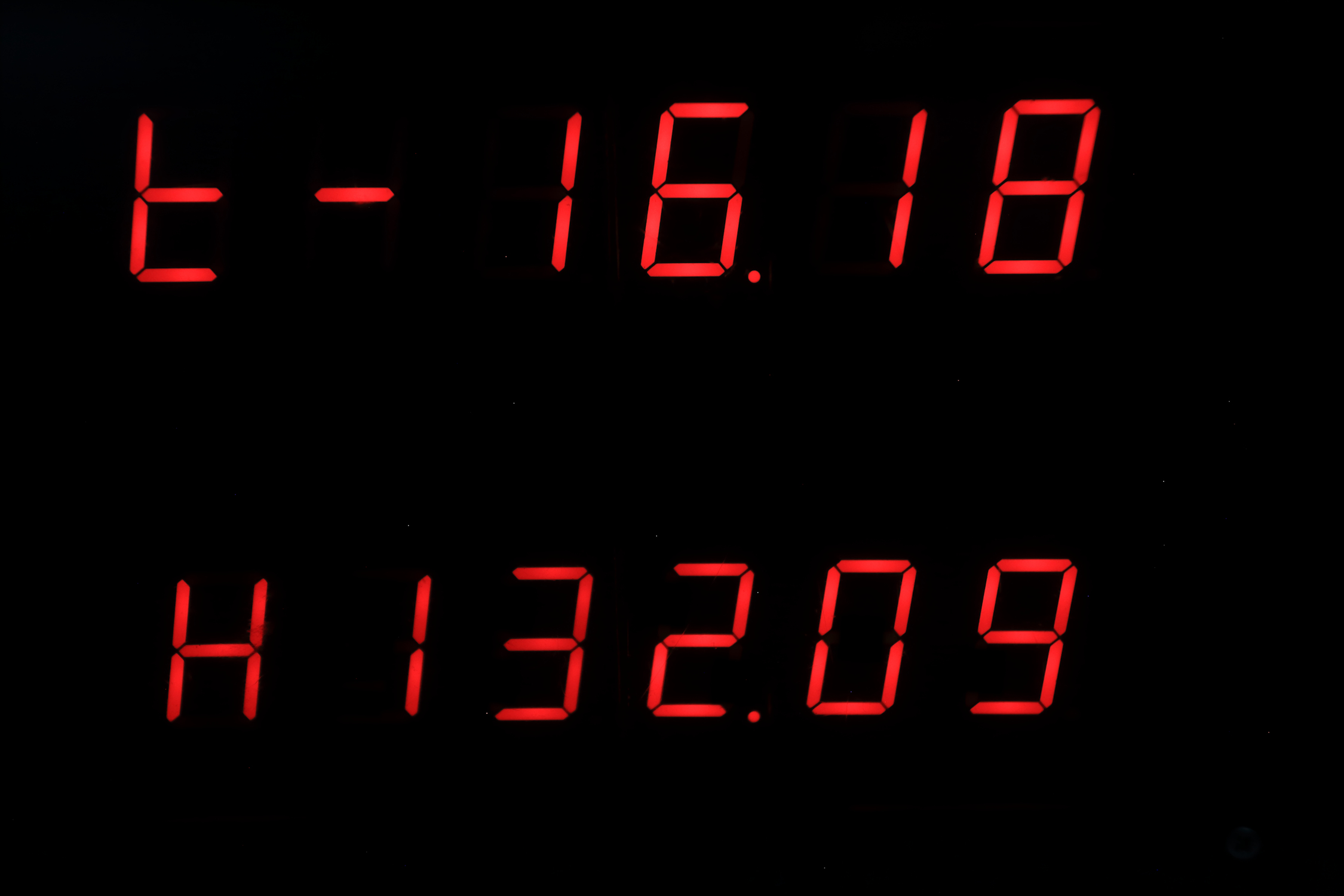
upper display : t = Equation of time
lower display : H = Angle between earth and moon
angle : 0 = new moon, 90 = first quarter, 180 = full moon, 270 = last quarter
Switch position 1100
upper display : u = sun rise position on the horizon ( 90 = east, begin of spring or autumn)
lower display : n = sun set position on the horizon ( 270 = west, begin of spring or autumn)
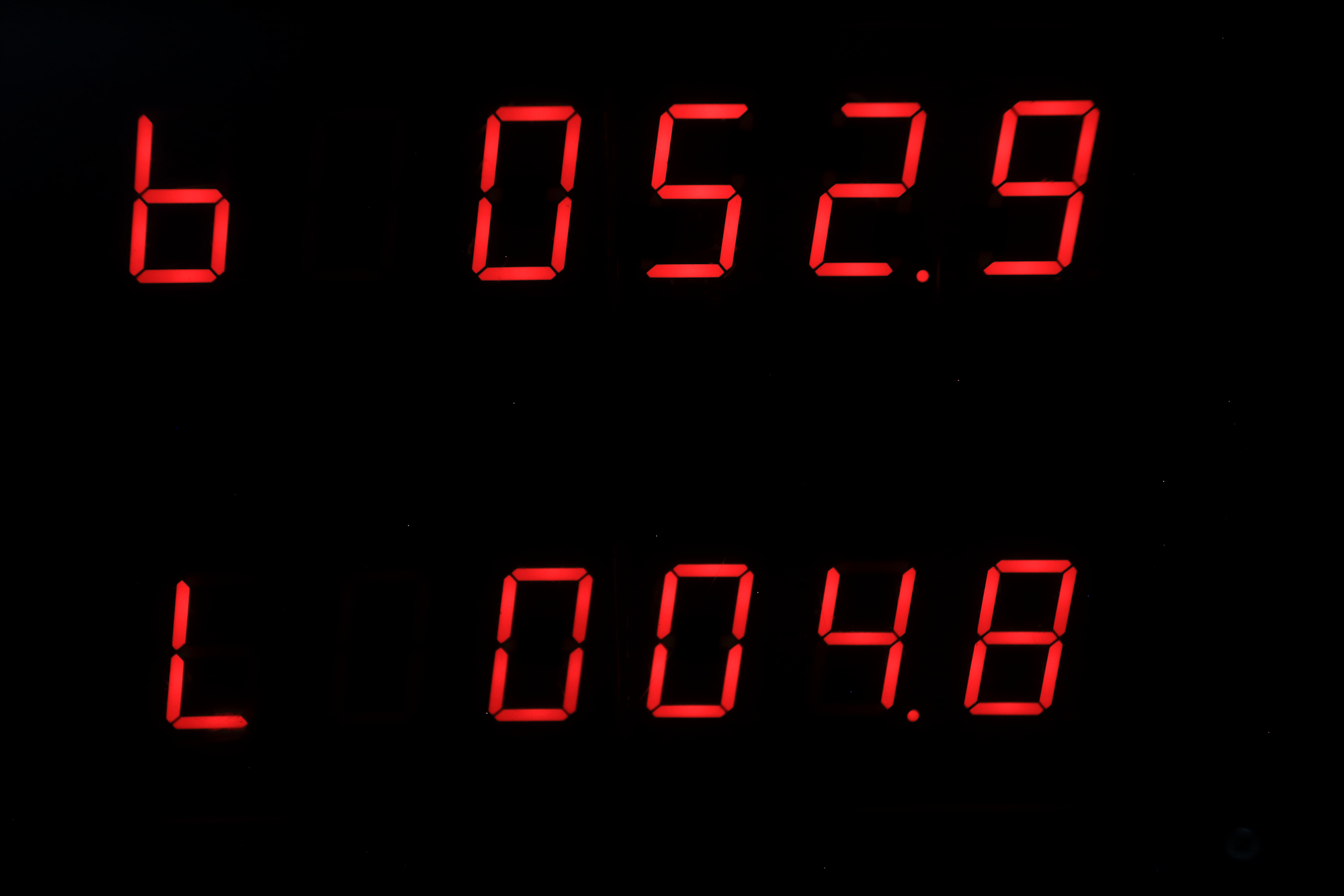
Switch position 1101
upper display : b = Latitude
lower display : L = Longitude
Switch position 1110
upper display : u = Time when the sun is at south position
lower display : The percentage of illumination of the moon
Switch position 1111
Night mode: when the hour is between 0 and 8 am, the displays are blank,
otherwise: it shows:
upper display: time
lower display: Date (day, month, year)
High-Precision Solar Alignment
This project goes beyond simple timekeeping, calculating the position of the sun and celestial bodies based on the current date and location.
- Ephemeris Calculation Core: The Arduino uses the precise time from a DS3231 RTC and pre-set Latitude/Longitude coordinates to calculate local "Sunrise" and "Sunset" times.
- Automatic Solar Tracking: (Advanced version) Outputs these calculations as PWM signals to a solar tracker mount, ensuring panels are always pointed at the optimal angle for energy generation.
Temporal Accuracy
- Temperature Compensation: The DS3231's internal TCXO (Temperature Compensated Crystal Oscillator) ensures the clock remains accurate within ±2 minutes per year, even in extreme outdoor environments.
Explanation of the code
Time
look at the code : void Tijd()
//---------------------------------------------------------------------------------
void Tijd() { // time on display1 and date on display2
int test;
test = a % 2;
if (test == 0) {
display1( Data1[f], Data1[e] - 1, Data1[d], Data1[c], Data1[b], Data1[a]);
} else {
display1( Data1[f], Data1[e], Data1[d], Data1[c] - 1, Data1[b], Data1[a]);
}
display2( Data1[h], Data1[g] - 1, Data1[j], Data1[i] - 1, Data1[m], Data1[k]);
// when you put '' - 1'' after "]", the display dot will be lit, so in the
display2(.....) line, display 2 and 4 have their dots lit.
}
//---------------------------------------------------------------------------------
The first variable Data[f] is the first upper left display
e and f are the hour variables. When the hour is 15,
then f=1, the program search in the array Data1[f], and finds at the second position (zero is the first, computers count from zero) the number 243, and that is the information that goes to the shiftregister. 243 is number one for the first display, this information lasts only very short, then the next Data1[e] is read by the program and then the program finds at position 6 the number 37 and that is the information that goes to the shiftregister. 37 is number 5 for the second display, etc......
So, in the line display1(x,x,x,x,x,x); there are 6 variables for the upper display, the first is the first left display, the second the second display etc...
In the line display2(x,x,x,x,x,x); there are 6 variables for the lower display, the first is the first left display, the second the second display etc...
When you see only a number, that is a selfmade figure, when you see the number 67, on the display you see d, 25 is P, 143 is L, 195 is j, 15 is t, 199 is u
95 is r, 18 is H, so you can make some text too