This project is about getting Lego Cannons to shoot automatically. I like playing with legos, and I like using Arduinos, so I decided to do this project in my free time. The Servo motors, with their horns attached, spin around hitting the lever and shooting the cannon. A great first, second, or third project for beginners!
This is a step by step guide on how to make it.
Step 1: The Hardware
Step 1 Part 1: Hardware Basics
Start with 5V going to the positively charged row and GRND going to the negatively charged row. It'll look like this -
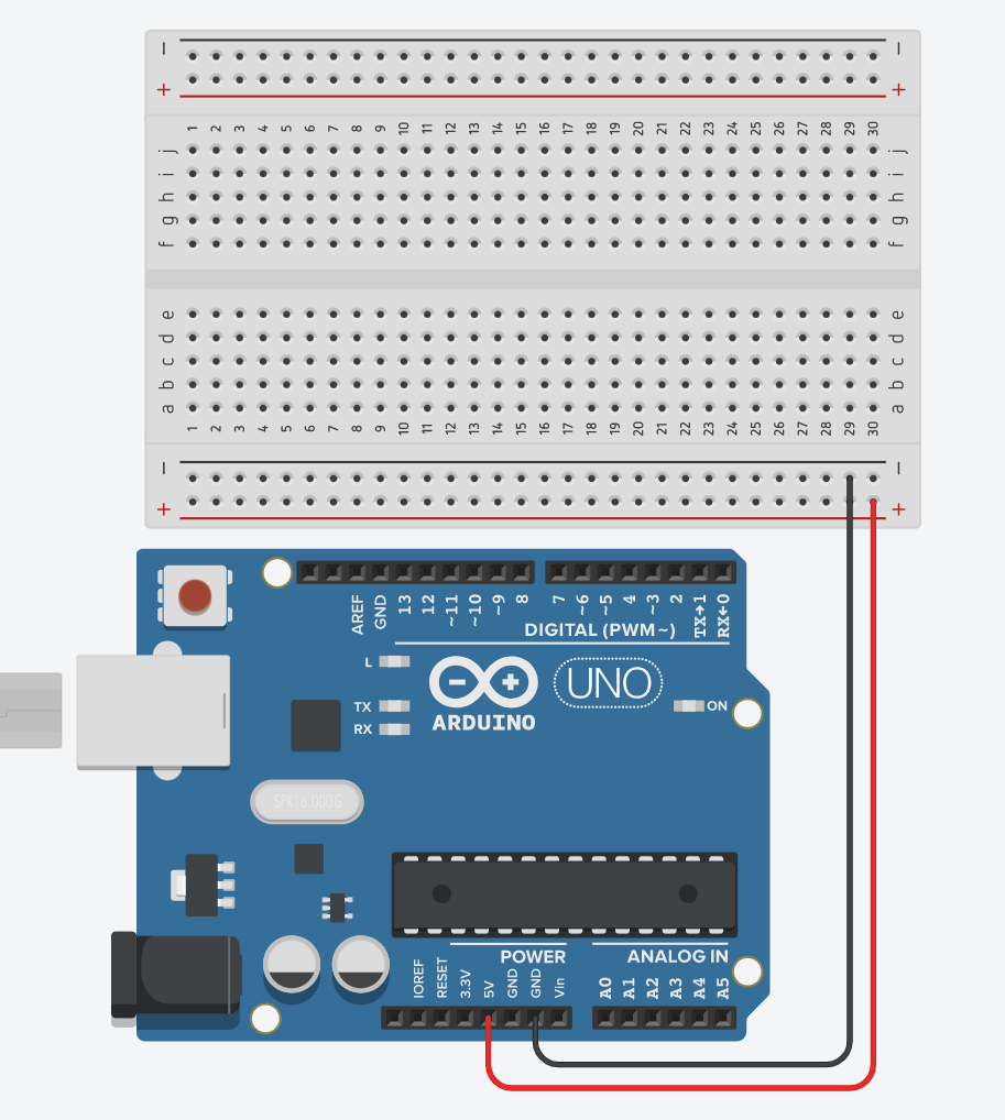
Technical Note: The circuit diagram might show VIN pin connected to the positive rail, but for actual use with multiple servo motors, using excessive voltage through VIN can damage the servos or cause overheating (Overload). Therefore, it is recommended to use a stable 5V from a regulated power port only.
Step 1 Part 2: Hooking up Servo #1
The Servo has three wires - the orange/yellow (signal) one will take up a slot in the DIGITAL (PWM~), the red one (Power) will go to VIN (which is any pin in the positive row), and the black/brown wire (GRND) will go to the negatively charged row connected to the GRND pin on the Uno. The Digital pin that I used for my first servo is 7. Here is how the schematic looks like when the first servo is hooked in -
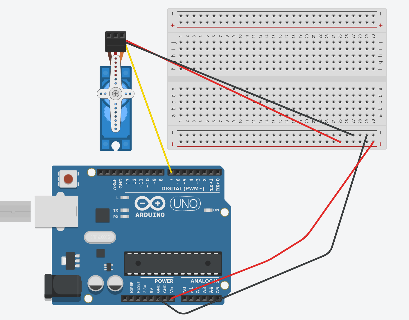
A Servo Motor typically has 3 wires, each with a different function as follows:
- Orange or Yellow Wire (Signal): This wire receives the PWM (Pulse Width Modulation) signal to determine the rotation angle. Here, we will connect it to a DIGITAL port (with the ~ symbol) on the Arduino Uno; I chose pin 7.
- Red Wire (Power/VCC): Connects to the 5V positive power on the breadboard.
- Black or Brown Wire (Ground): Connects to the negative rail on the breadboard, which is connected to the GND pin of the Arduino.
Step 1 Part 3: Wiring up the rest of the Servos
Once you get the hang of it with the servos, the rest should be a breeze. One thing to note, however - you have to keep consistent with the Digital Pins you attached with your servo in the code.
For example, the code (which can be found at the bottom of the page), states-
secondCannon.attach(8);
Therefore, the second Servo must be connected to the digital pin 8.
In the same way, the third Servo must be attached to the digital pin 6, and the fourth should be attached to the ninth digital pin.
However, these can be changed so that they are in any order you want them to be. Just make sure you are changing both hardware and software for consistency, otherwise, the code will not work.
To run with the code provided at the bottom, this is how the schematic should look like-
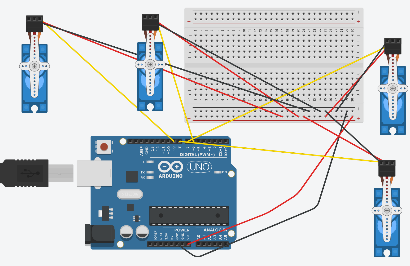
In this project, I assigned the connection positions in the following order:
- Second Cannon (secondCannon): Connects to Digital pin 8
- Third Cannon (thirdCannon): Connects to Digital pin 6
- Fourth Cannon (fourthCannon): Connects to Digital pin 9
You can change these ports as needed, but make sure to modify both the circuit and the program to match. Otherwise, the system will not be able to control the correct motors.
Note: Although the circuit diagram may look complex due to the large number of wires, if you consider each part separately, you will find that it is simply a repetition of the same steps, just changing the control pins.
Congratulations! You have officially completed the hardware portion of this project.
Step 2: The Software
Now, copy and paste the code at the bottom of the page onto an Arduino sketch, and upload it. Make sure you have the Servo library before uploading the code, otherwise it will not work! Below is a step-by-step guide explaining the code and what it means when running the program.
What's essential is installing the Servo.h library, which is a standard library that allows us to easily control the motor's angle without having to write PWM signal control commands ourselves.
#include <Servo.h>  //Including the library for the Servos
Servo firstCannon;  //Defining the First Cannon as a Servo
Servo secondCannon;  //Defining the Second Cannon as a Servo
Servo thirdCannon;  //Defining the Third Cannon as a Servo
Servo fourthCannon;  //Defining the Fourth Cannon as a Servo
This code sets up the Servo.h library, which will play a fundamental role in the code. This can be shown by the following lines, using the library to define four cannons as Servos, or motors that can be rotated 180 degrees. This initial code creates "software representations" for the servos, allowing us to send commands to each motor independently.
void setup() {  //Setup code, or code that is only run once
 Serial.begin(9600);  //Start the Serial communication
 Serial.println("Defend the Clones! Set up the defenses!")  //Prints something in the Serial Monitor
 firstCannon.attach(7);  //Attach Digital Pin 7 to First Cannon
 secondCannon.attach(8);  //Attach Digital Pin 8 to Second Cannon
 thirdCannon.attach(6);  //Attach Digital Pin 6 to Third Cannon
 fourthCannon.attach(9); //Attach Digital Pin 9 to Fourth Cannon
}
The void setup() code is used within almost any Arduino project, and it is code that is only run once. In this case, we are starting the newline Serial Communication at 9600 baud. Then, we are printing things in the Serial Monitor. In order to program the Servos, we have to connect their names the their respective digital pins. This is the purpose of the .attach() piece of code. The void setup() function serves to assign roles to each Arduino pin using the .attach() command to specify which servo is connected to which pin, as well as initiating Serial Communication so we can monitor the operating status via the computer screen.
void loop() {  //Loop code, or code that is run an infinite amount of times
 Serial.println("Beginning firing sequence")  //Print something in the Serial Monitor
 firstCannon.write(180);  //Swerve the first servo 180 degrees, setting off the first cannon
 delay(100);  //Wait for 1/10 of a second
 firstCannon.write(0);  //Swerve the Servo back to original position in preparation for reload
 delay(1000);  //Wait for 1 second
 secondCannon.write(180);  //Swerve the second servo 180 degrees, setting off the second cannon
 delay(100);  //Wait for 1/10 of a second
 secondCannon.write(0);  //Swerve the Servo back to original position in preparation for reload
 delay(1000);  //Wait for 1 second
 thirdCannon.write(180);  //Swerve the third servo 180 degrees, setting off the third cannon
 delay(100);  //Wait for 1/10 of a second
 thirdCannon.write(0);  //Swerve the Servo back to original position in preparation for reload
 delay(1000);  //Wait for 1 second
 fourthCannon.write(180);  //Swerve the first fourth 180 degrees, setting off the fourth cannon
 delay(100);  //Wait for 1/10 of a second
 fourthCannon.write(0);  //Swerve the Servo back to original position in preparation for reload
 delay(1000);  //Wait for 1 second
 Serial.println("All cannons fired");
 Serial.println("Prepare for reload");
 delay(10000);
 Serial.println("Reloading Complete. Preparing to fire again")
}
This is the final piece of code, using the void loop() function that allows the following code to be run an infinite amount of times. Then, we print in the Serial Monitor that the cannons are about to fire. The Servos for each cannon should spin 180 degrees, then spin back to the original position, one at a time. After that, there should be 10 seconds (reloading time) until the process repeats itself again.
The logic in void loop() is designed as Sequential Logic, where each cannon fires in sequence. The write(180) command sends an angle value to the servo horn, moving it to strike the Lego firing mechanism, and write(0) retracts the horn to facilitate easy reloading. After all 4 shots, the system will pause for 10 seconds to allow the player time to reload before the next firing cycle begins.
If you have any other issues when uploading the code, you can comment in the comments section and I will respond ASAP. If it works, then move on to the next step.
Step 3: Installation
The last step requires the lego cannons and some old-fashioned regular tape. The lego cannon looks like this -

Installation Technique:
- Run the code. See which way the servo turns.
- Observe the rotation direction of the servo horn when it moves to 180 degrees.
- Tape the servo onto the lego cannon so that its trajectory sets it on a collision course with the lever on top of the cannon in the picture above. Use adhesive tape to attach the servo to the side or top of the Lego cannon, estimating the distance so that the servo horn precisely hits the grey lever on top of the cannon.
Good job! You have officially finished this project. Like I said, comment in the section below if you have any questions.
If you liked this project, check out these links -