Making model train layouts is a great hobby, automating them will make it a lot better! Let us take a look at some of the advantages of its automation:
- Low-cost operation: The whole layout is controlled by an Arduino microcontroller, using an L298N motor driver, their cost is almost nothing as compared to traditional train control throttles and power packs.
- Ideal to put up at a display: Since no human interference is required to keep a control on the layout, you can use it at a display where you cannot be always present to control the train and the turnouts.
- Great for microcontroller hobbyists: If you are or want to start with Arduino and programming, this is a great project for you to practice your skills.
If you are interested, you can also check the previous version of this project which is even simpler.
So, without further ado, let's get started!
Step 1: Watch My Project Working
Step 2: Get All the Parts and Components
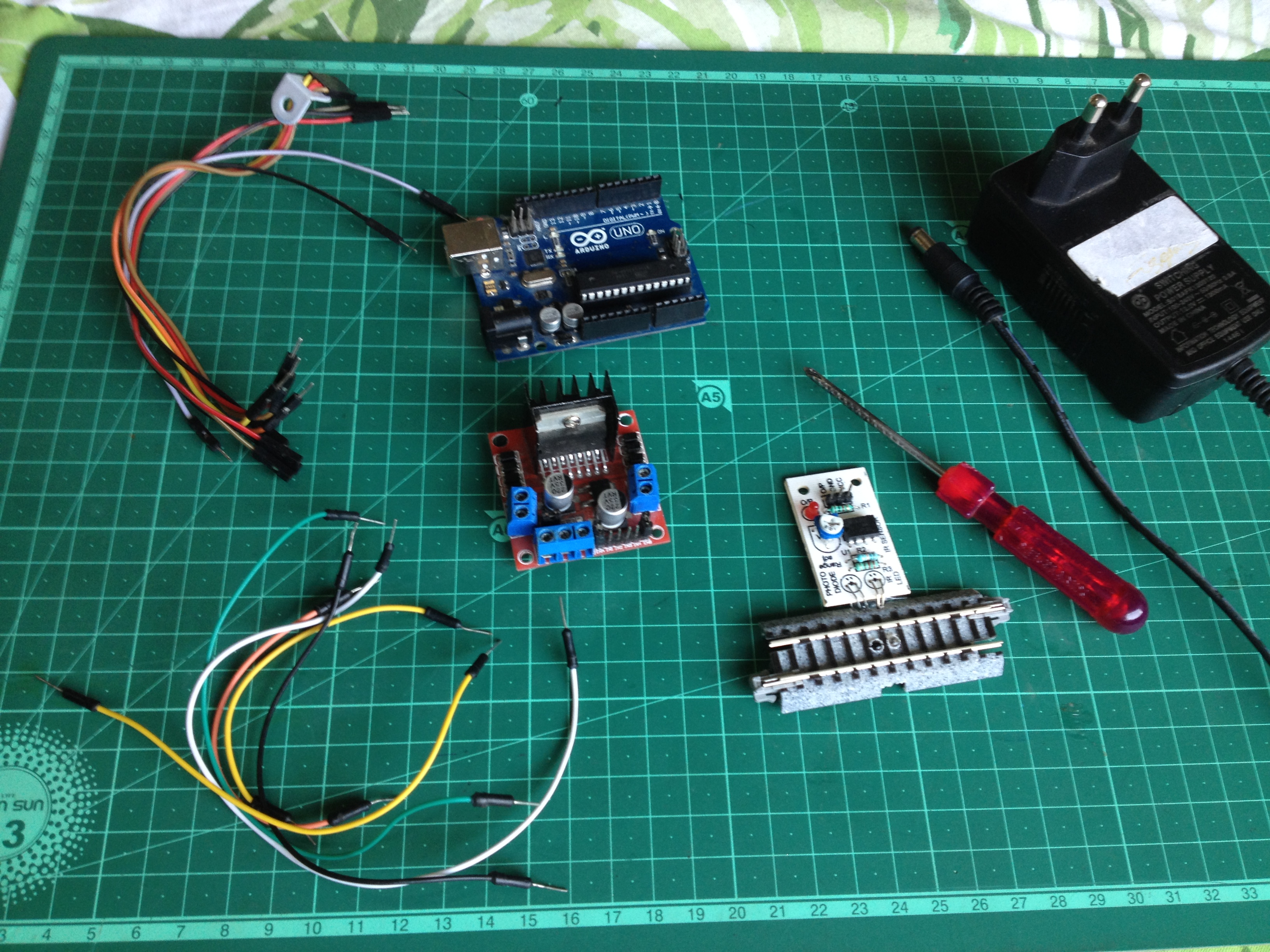
To start, make sure you have all of the following:
- An Arduino microcontroller board, UNO is preferred.
- An L298N dual H-bridge motor driver board.
- 6 male to male jumper wires.
- 7 male to female jumper wires.
- A screwdriver.
- A 12 volt-DC power supply adapter.
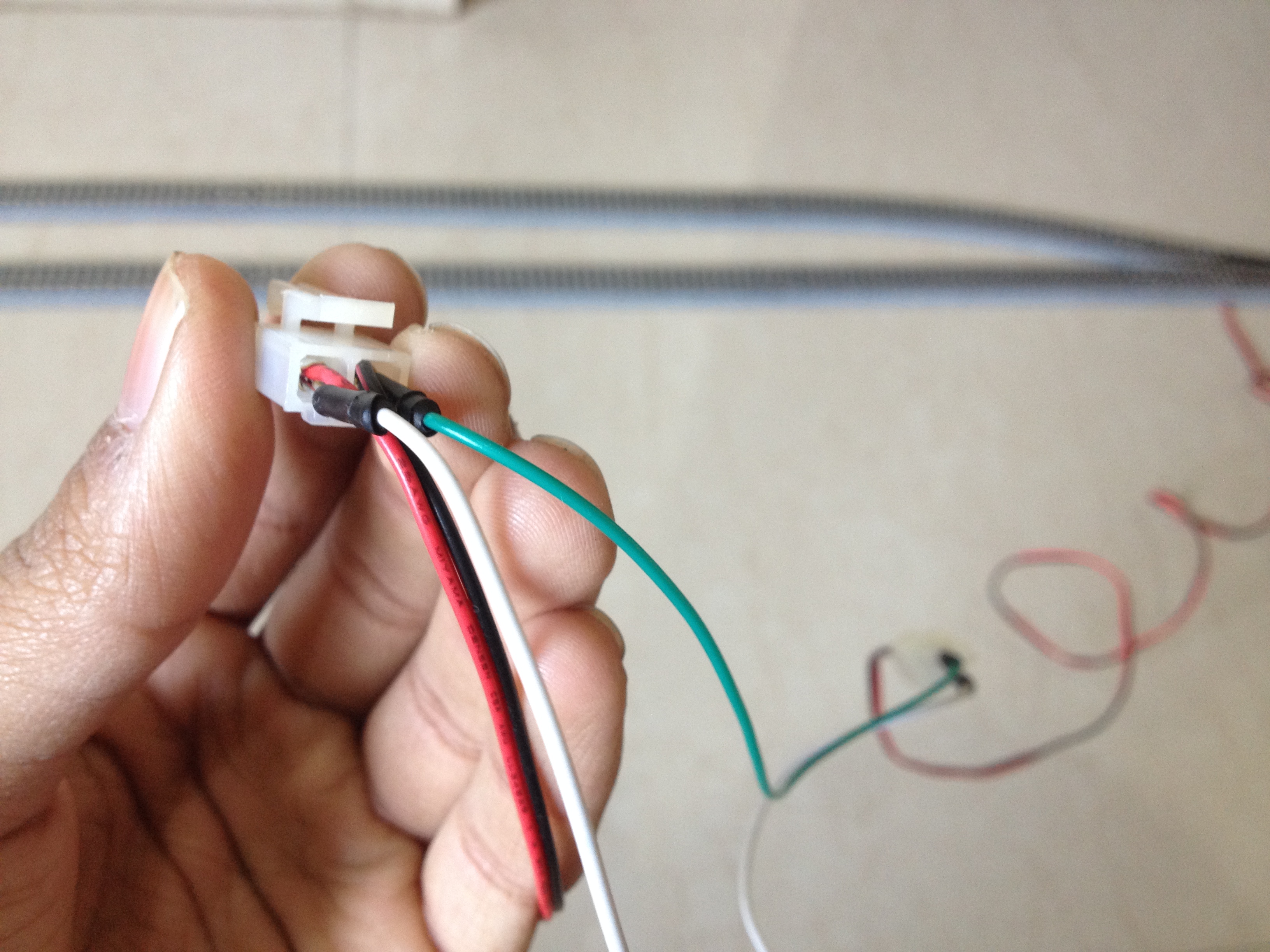
- A track segment with IR proximity sensor attached on the underside(I used a Kato S62 track)
Step 3: Upload the Program to the Arduino Board
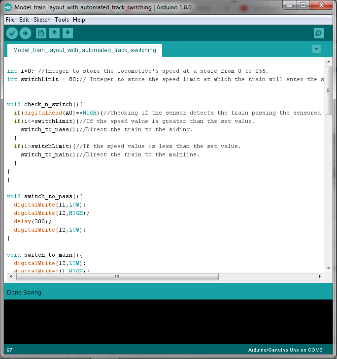
Download the Arduino IDE from here if you don't have it on your computer. Then download and open the given file.
Step 4: Lay the Tracks and Make the Layout
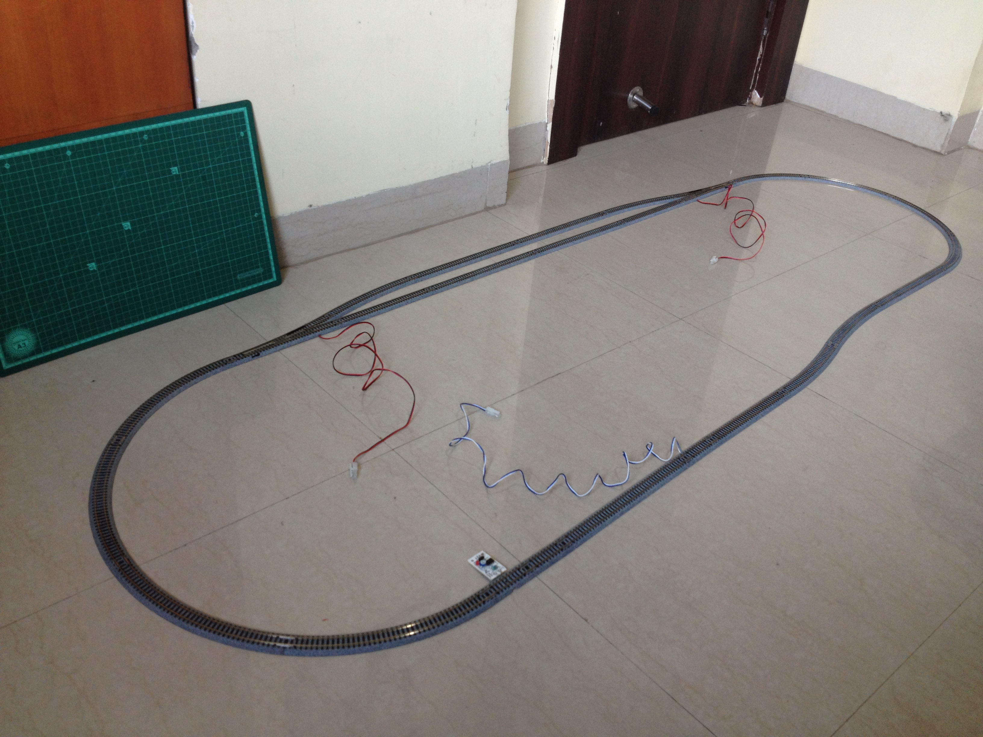
Make an oval loop with a passing siding somewhat as shown above. Make sure the distance between the sensor track and the first turnout the train will cross after crossing the sensor track is greater than the length of the train such that no part of the train is over the sensor track when it crosses the turnout.
Step 5: A Circuit Schematic Is Always Helpful
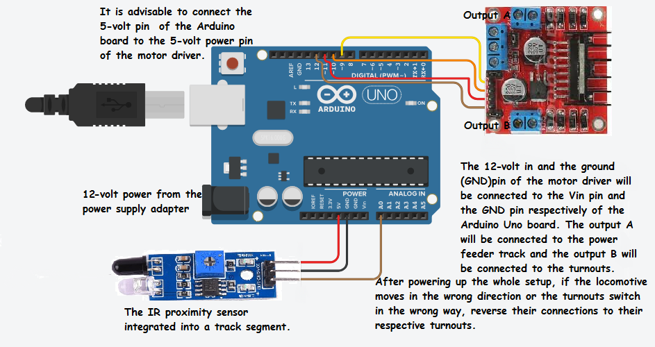
Make sure you go through the full circuit schematic and all of the details before proceeding.
Step 6: Connect the Turnouts to the Output of the L298N Driver Board
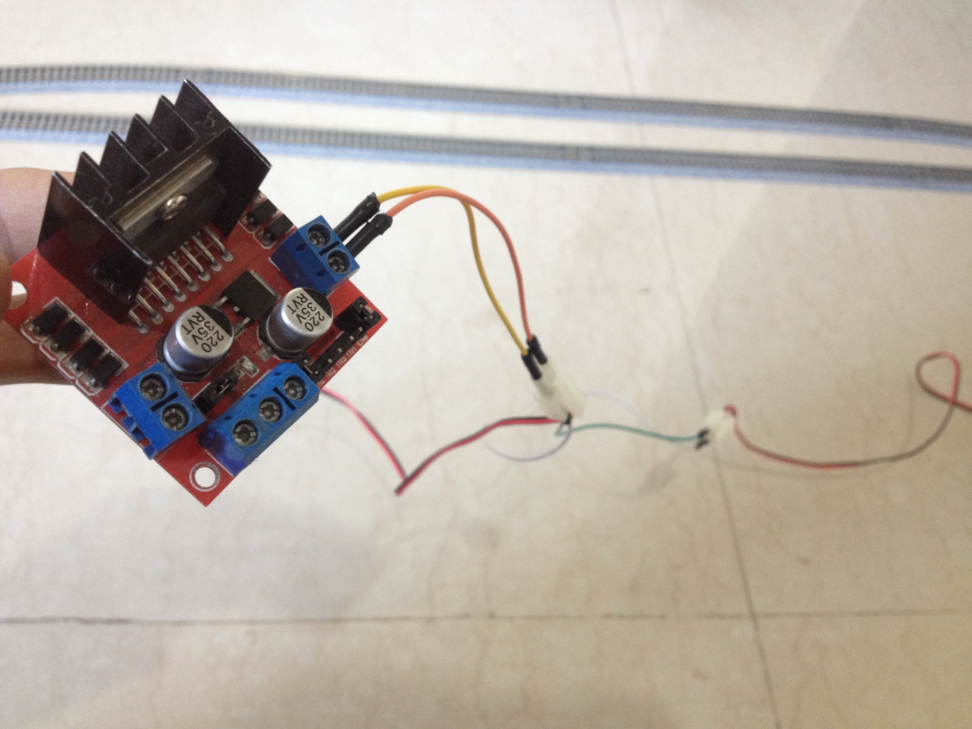
Connect the red and the black wires of both the turnouts respectively to each other, resulting in a parallel connection. Then, connect the red wires to the out4 and the black wires to the out3 terminal of the motor driver board.
Step 7: Connect the Power Feeder Track to the Remaining Output of the L298N Driver Board
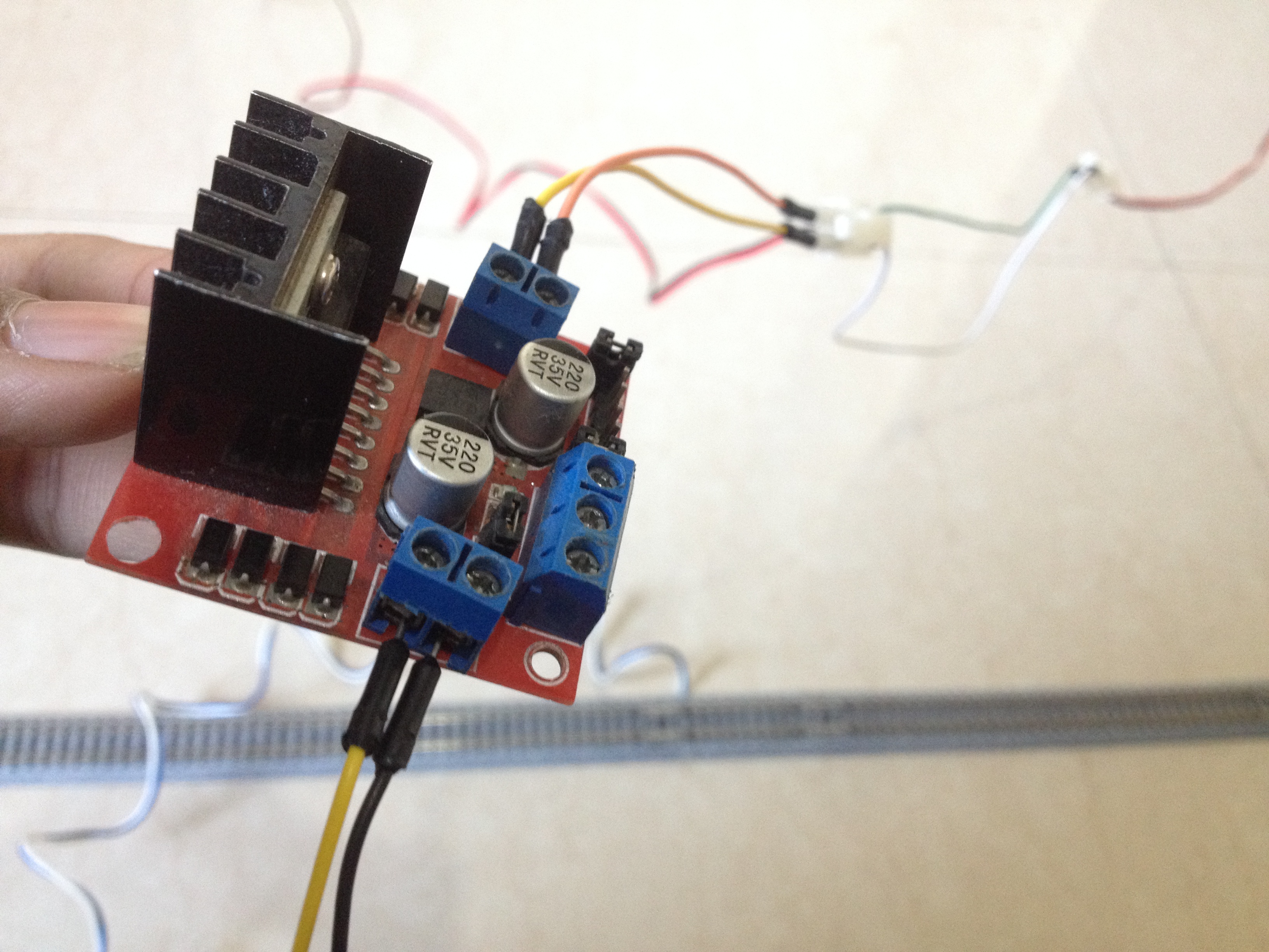
Connect the power feeder's white wire to the out1 and the blue wire to the out2 terminal of the motor driver board.
Step 8: Connect the L298N Driver Board to the Power Pins of the Arduino Board
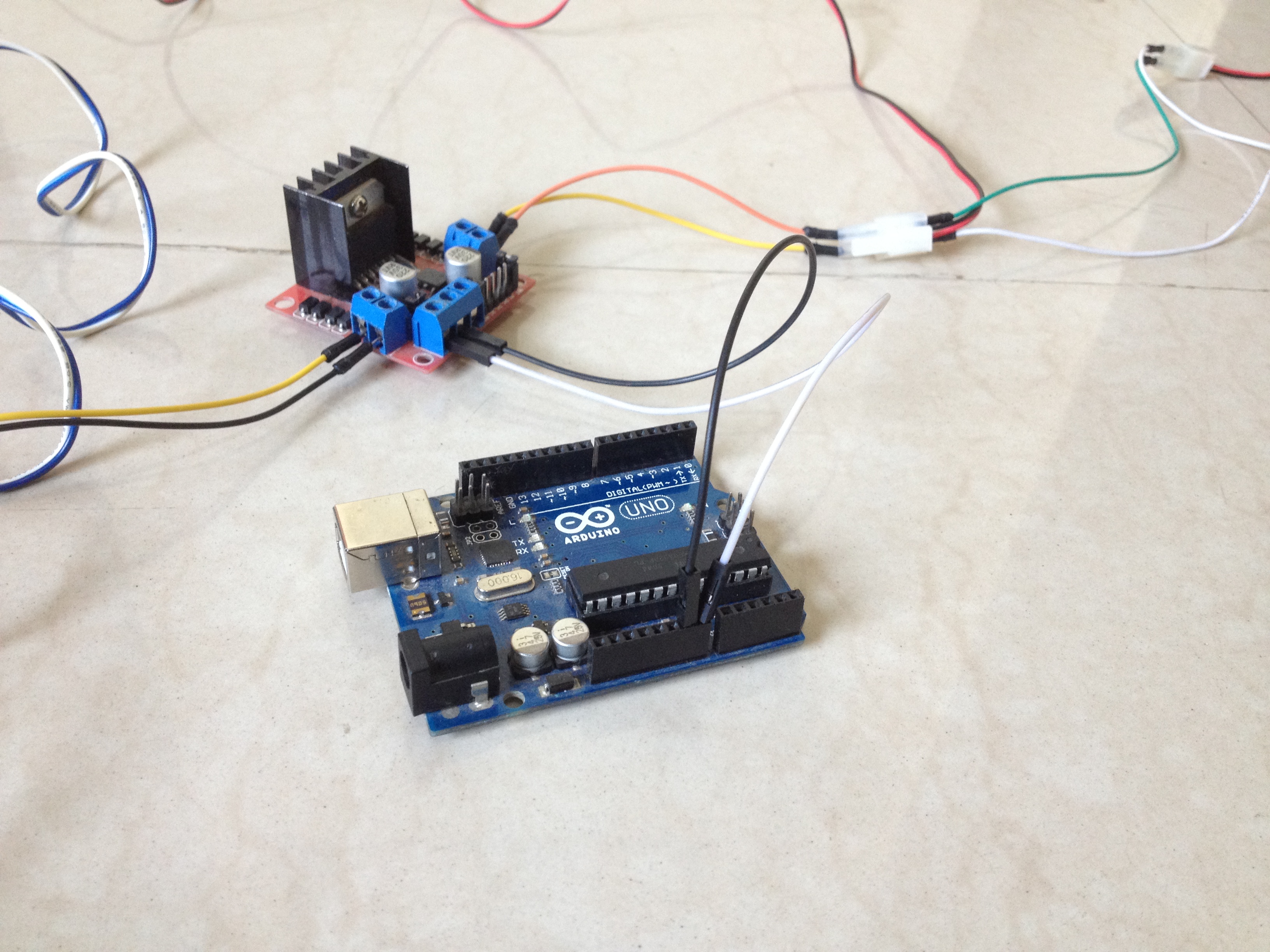
Connect the 12-volt pin to the VIN pin of the Arduino board, the GND pin to the GND pin of the Arduino board, and preferably, the 5-volt pin of the motor driver to the 5-volt pin of the Arduino board.
Step 9: Connect the Sensor to the Arduino Board

Connect the VCC pin of the sensor to the 5-volt pin of the Arduino board, GND pin to GND pin of the Arduino board, and the OUT pin to the A0 pin of the Arduino board.
Step 10: Connect the Input Pins of the Motor Driver to the Arduino Board
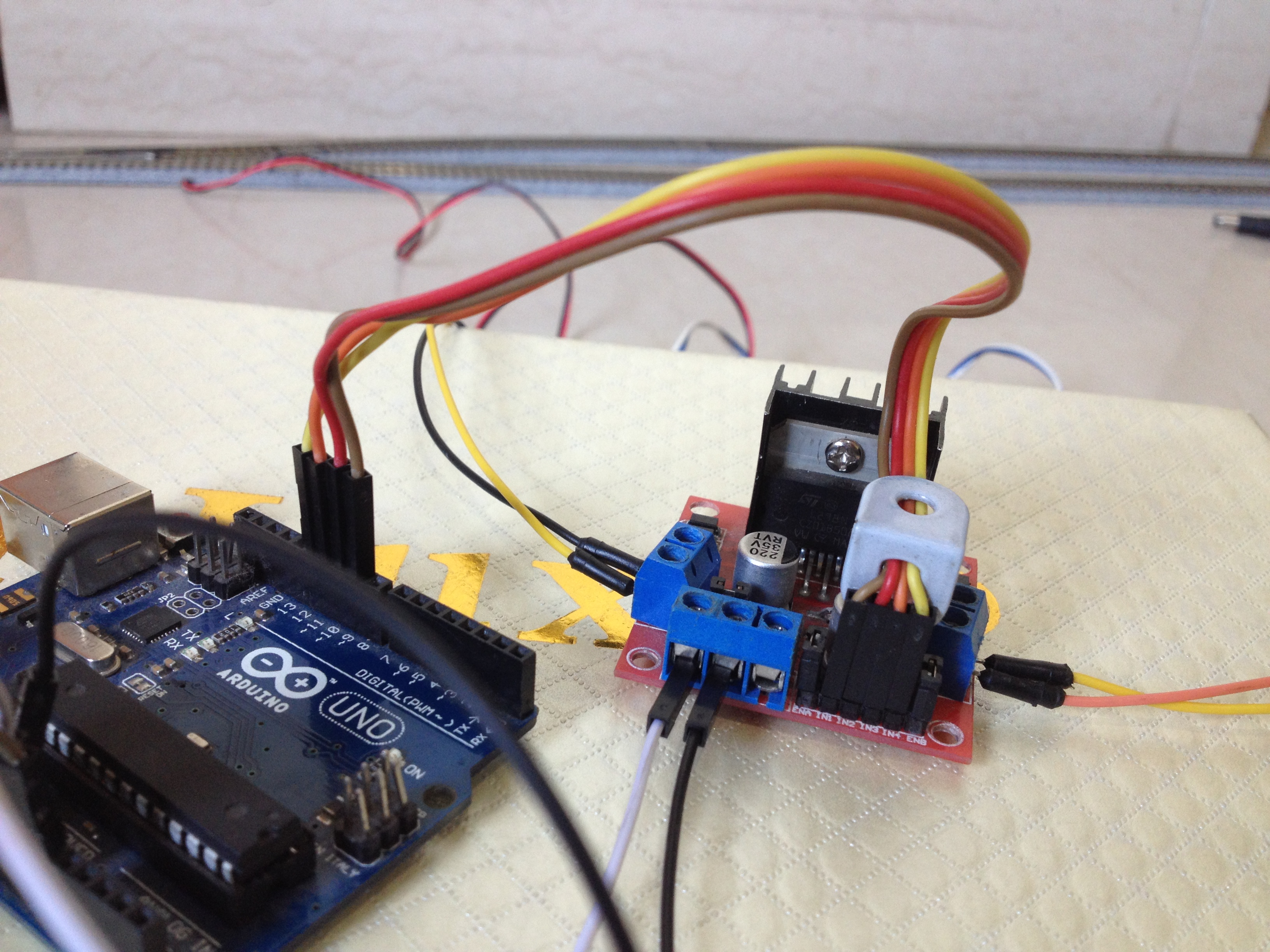
Connect the digital pins of the Arduino board to the input pins of the motor driver board as follows:
- D9 to IN1
- D10 to IN2
- D11 to IN3
- D12 to IN4
Step 11: Place the Train on the Tracks
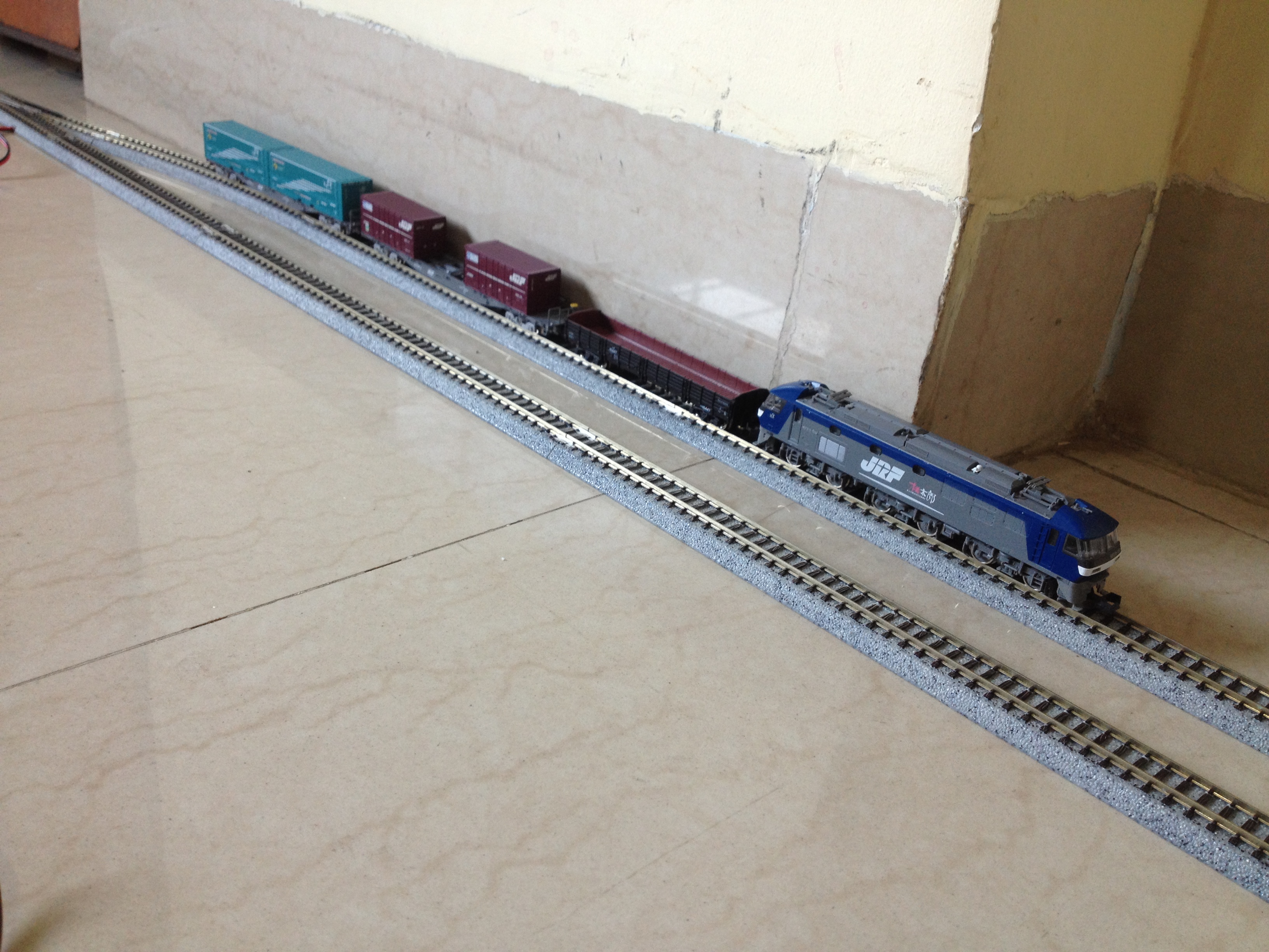
After checking all of the wiring connections, place the train on the siding.
Step 12: Power Up the Setup
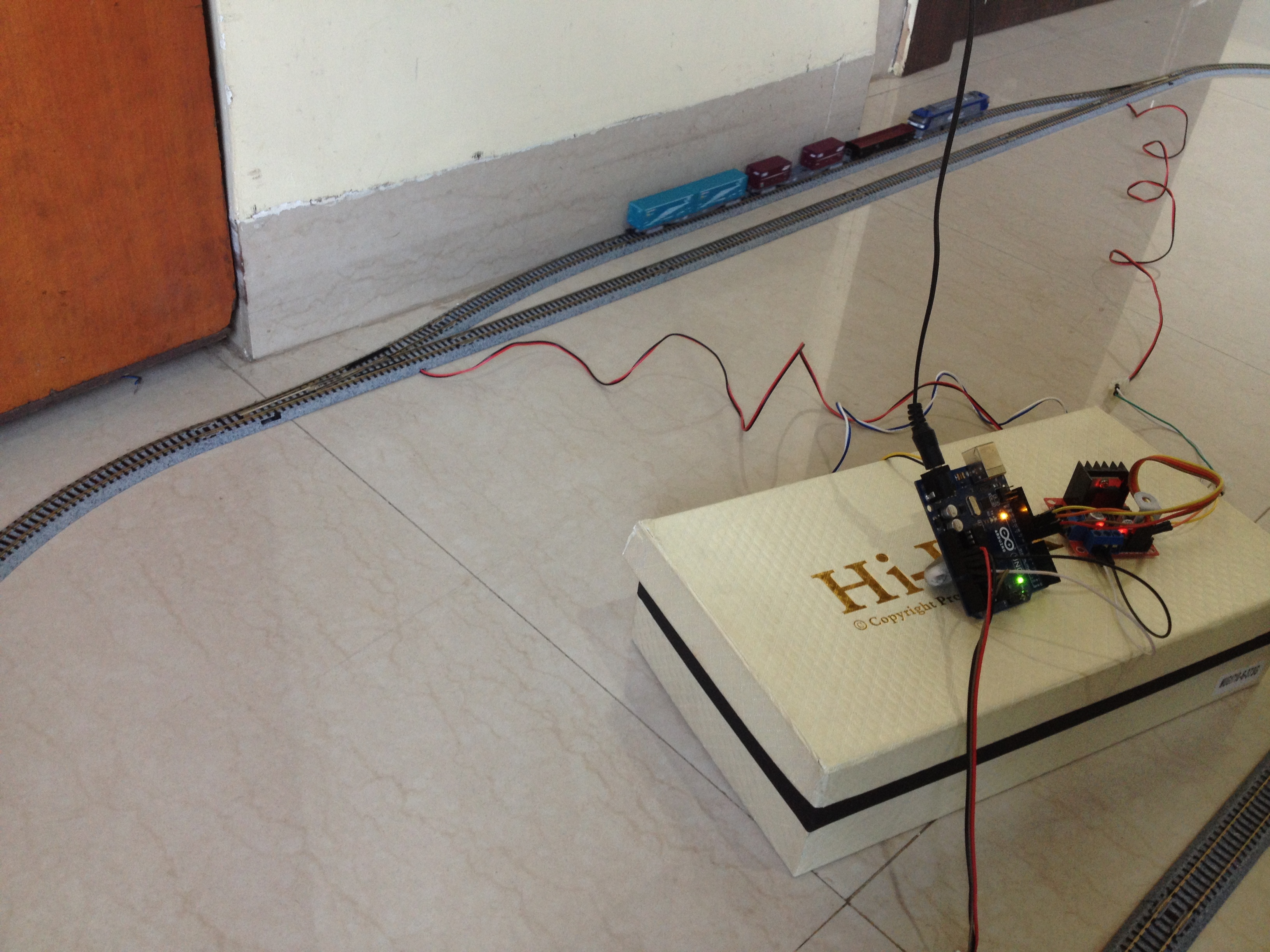
Power up the setup and make sure the turnouts get switched to the siding, if not then just reverse the connections of the turnouts made with the motor driver. Also, make sure the train starts to move to forward direction. Reverse the feeder track's connection with the motor driver if the train moves in the wrong direction.
Step 13: It's DONE!
The project is complete, for now. You can tinker with the Arduino code to change the functionality of the layout, add more sidings, etc. It's all customizable! I would love to know about any modifications you make to this project. Let me know in the comments below. All the best!
EXPANDED TECHNICAL DETAILS
Moving beyond standard block spacing, the Automated Passing Siding addresses a specific geometry problem in model railroading: a single-track loop containing two trains running in opposite directions. The system must automatically detect an impending head-on collision, switch one train onto a side track, hold it, and release it once the express train passes.
Multi-Stage Boolean Logic
The Arduino acts as the central dispatch tower, maintaining incredibly complex state awareness using boolean variables.
- The Approach Sensors: A Reed Switch or Hall Effect sensor is placed 3 feet before the switch.
bool Train1_Approaching = true;(Magnet on bottom of train triggers sensor).- The logic checks the status of the main track:
if (Main_Track_Occupied == true) { Route_To_Siding(); } - The Switch Throw: A Micro Servo physically throws the mechanical turnout switch left. The Arduino cuts 12V DCC power specifically to the Siding track using a relay, physically trapping Train 1!
Unlocking the Mainline
Train 2 (on the main track) speeds past the siding.
- An exit sensor detects Train 2 has cleared the chokepoint.
Main_Track_Occupied = false; - The Arduino commands the 12V relay to restore power to the Siding track.
- Train 1 roars back to life!
- The Arduino waits 5 seconds, then commands the Micro Servo to return the physical track switch to the "Straight/Mainline" position.
Requisite Architecture for Advanced Expansion
- Arduino Mega: Crucial for tracking massive amounts of boolean variables and handling dozens of I/O interrupts simultaneously in larger layouts.
- Hall Effect or Reed Switch Sensors (x6 or more).
- Micro Servos (SG90) mounted beneath the model track.
- Multi-Channel 5V Relay Boards (To selectively cut 12V power to specific track blocks).
- A reliable 12V, 2-to-3 Amp power supply for the locomotives.