As a teacher, taking attendance traditionally (roll call) is a time-consuming task, if automated the instructor can focus on other teaching activities. In this project RFID reader module and RFID cards will be used to implement an automatic attendance system.
The classes are conducted inside a confined space and is difficult to attend a lecture if the environment is too hot or too cold. To achieve effective learning, the right physical environment inside the classroom should be maintained. The Relative Humidity and Temperature sensor(DHT11) will be used in this project to monitor the temperature and humidity and inform if the values are out of range.
Libraries and Definitions
Before the start of the code, the libraries need to be included in the program. The pin numbers that are physically connected to the Arduino board are defined. The instances of the RFID receiver (mfrc522) and the DHT sensor (dht) that will be used for the data acquisition are created. A variable called student is created, which is a two-dimensional array of strings that stores the student name and the associated RFID tag ID.
#include <SPI.h>
#include <MFRC522.h>
#include "thingProperties.h"
#include "DHT.h"
#define DHTpin 2
#define DHTTYPE DHT11
#define SS_PIN 11
#define RST_PIN 12
MFRC522 mfrc522(SS_PIN, RST_PIN);
String student[6][2] = {
 {"90 17 34 37", "Ana" },
 {"D3 AA D0 45", "Paula" },
 {"52 98 81 39", "Renato" },
 {"71 E4 AE 20", "Luis" },
 {"E3 72 52 1A", "Angela" },
 {"91 39 45 20", "Maria" }
};
DHT dht(DHTpin, DHTTYPE);
Setup
The setup() function is executed only once when the board is powered up or when the reset button is pressed. The serial connection is initialized with a baud rate of 9600. The DHT sensor acquisition calls the function begin() to start the acquisition.
Some Arduino IoT Cloud functions are called to initialize properties, begin the connection, set the debug message levels and to print any debug information.
void setup() {
 // Initialize serial and wait for port to open:
 Serial.begin(9600);
 delay(1500);
 // Defined in thingProperties.h
 initProperties();
 // Connect to Arduino IoT Cloud
 ArduinoCloud.begin(ArduinoIoTPreferredConnection);
 setDebugMessageLevel(2);
 ArduinoCloud.printDebugInfo();
 delay(4);
 dht.begin();
}
Main function - Loop
The loop() function in Arduino includes the begin of the SPI communication and the mfrc522 initialization. At first, these two initializations were done at the setup phase, but were moved to the loop due to a bug when the Arduino Cloud is updated. It changes pin 10 to input, breaking the SPI communication. The solution was to initialize the SPI communication on every loop to reset pin 10 to output mode.
 void loop() {
 SPI.begin();
 mfrc522.PCD_Init();
 if ( mfrc522.PICC_IsNewCardPresent()) {
   if (mfrc522.PICC_ReadCardSerial()) {
     String content = "";
     byte letter;
     for (byte i = 0; i < mfrc522.uid.size; i++)
     {
       content.concat(String(mfrc522.uid.uidByte[i] < 0x10 ? " 0" : " "));
       content.concat(String(mfrc522.uid.uidByte[i], HEX));
     }
     //Serial.println(content.substring(1));
     content.toUpperCase();
     for (int i = 0; i < 6; i++) {
       if (content.substring(1) == student[i][0])
       {
         msg_Attendance = "Attendance Recorded for Student: " + student[i][1] ;
       }
     }
     Serial.println(msg_Attendance);
   }
 }
 dht_sensor_getdata();
 delay(500);
 ArduinoCloud.update();
}
After the initialization of the mfrc522, the function **PICC_IsNewCardPresent()**is called. In case a new card is detected, the function **PICC_ReadCardSerial()**reads the ID information from the RFID card. The ID is a variable of type string called content. It is converted to upper case to be compared with the array of student IDs stored in the definition part of the program. When the ID read from the card matches a student from the record, the attendance is recorded and stored in the variable msg_Attendance.
The dht_sensor_getdata() function is called, more detailed information in the next section. A short delay of 500 ms is introduced before calling the ArduinoCloud.update() function. This function sends all four variables to the cloud: temperature,humidity,msg_Attendance and msgTempHum.
DHT sensor function
The function dht_sensor_getdata() was created to read the humidity and temperature data from the DHT11 sensor. The dht.h library imports the functions readHumidity() and readTemperature().
The if-else conditional checks for the thresholds of low temperature (20ºC) and high temperature (27ºC) and then sends a message to the dashboard. This could be implemented with an actuator (to turn on or off the air conditioner) or an alarm in the real classroom.
void dht_sensor_getdata()
{
 float hm = dht.readHumidity();
 Serial.print(F("Humidity "));
 Serial.println(hm);
 float temp = dht.readTemperature();
 Serial.print(F("Temperature "));
 Serial.println(temp);
 humidity = hm;
 temperature = temp;
 if (temp > 27) {
   msgTempHum = "Temperature = " + String (temperature) + "  Humidity = " + String(humidity) + " -> High ";
 }
 else if (temp < 20) {
   msgTempHum = "Temperature = " + String (temperature) + "  Humidity = " + String(humidity) + " -> Low ";
 }
 else {
   msgTempHum = "Temperature = " + String (temperature) + "  Humidity = " + String(humidity) + " -> All ok ";
 }
}
EXPANDED TECHNICAL DETAILS
This project is a comprehensive integration that mimics commercial systems used in modern universities, handling data security alongside real-time environmental datalogging.
The Digital Roll Call (RFID)
The core of the attendance system is the MFRC522 RFID Reader, typically mounted at the classroom door. When a student taps their ID card (a passive NFC tag) against the reader, it uses radio waves to read the card's Unique Identifier (UID), which is a unique byte array (e.g., 90 17 34 37). In this implementation, the Arduino compares this UID against a pre-defined local array of student IDs and names. For a more scalable, enterprise-level system, this logic can be extended so the NodeMCU sends an HTTP POST request to a cloud database or Google Sheets script, marking that specific UID as "Present" with a precise timestamp.
Room Condition Monitoring
Simultaneously, the system monitors the classroom environment. The code uses a non-blocking structure (relying on the delay(500) in the main loop) to constantly poll the DHT11 sensor without disrupting the RFID scanner's operation. The DHT11 tracks temperature and humidity, with conditional logic providing immediate feedback if values fall outside a comfortable range (20°C to 27°C). This concept can be expanded to include additional sensors, such as an MQ-135 for air quality (CO2 levels), to warn if the room is getting stuffy. All this sensor data is bundled and sent to the Arduino Cloud dashboard for remote monitoring.
System Architecture & Scalability
The provided code uses an Arduino MKR GSM 1400, but the architecture is versatile. An ESP8266 or ESP32 NodeMCU is often preferred for more advanced projects due to its built-in Wi-Fi capability, making it essential for direct database API calls. The SPI bus communication with the MFRC522 is a critical hardware interaction. For user feedback, adding a 0.96" OLED display to show a "Welcome, [Student Name]!" message upon a successful card swipe significantly enhances the user experience. This project builds foundational skills in combining hardware SPI communication, sensor polling, and cloud-based data management, forming the basis for an enterprise-level smart classroom hub.
Step 0 - Setting up the Cloud
To connect to the Arduino IoT Cloud, first we need to create an account or sign in.
To use the Web-based editor, that has all cores and libraries already installed, we need to install the Create Agent Plugin. This agent will recognize the boards connected to the computer via USB.
Once in the Web Editor page we can see the board connected/disconnected, edit our code and upload when done.
However, there are other two options available:
- Classic offline Arduino IDE 1.8.13 (Integrated Development Environment) as – This was used for local sensor troubleshooting.
- New Arduino IDE 2.0 – has new features like debugging, code highlighting and autocomplete, which is currently in beta stage (when this project was prepared).
To select the IoT Cloud menu or Web Editor we can click at the top right button near the profile picture.
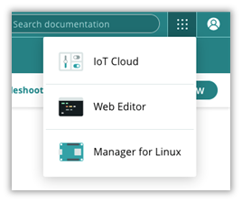
Once we select the IoT cloud Menu, there are a few options available, but in this project, we will focus on creating a Thing, associating a device and preparing a dashboard.
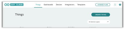
After clicking on "Create Thing" shown in the picture above. We followed the steps in this project:
- Step 1 - Device - associate a device to our Thing
- Step 2 - Add variables
- Step 3 - Change the network settings
- Step 4 - Edit the sketch, connect to the serial monitor
- Step 5 - Preparing a dashboard
- Step 6 - Acquire data from board sent to the cloud and export
Step 1 - Device
A new Thing won’t have a device configured, so the first step is to click and select device.
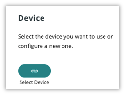
Any device previously used in the IoT cloud can be associated or a new device can be set up.
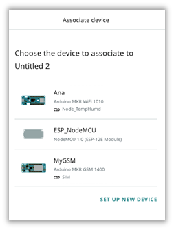
For this project we associated the device Arduino MKR GSM 1400 to the Thing, but any other board can be used like Arduino MKR WiFI 1010 or NodeMCU.
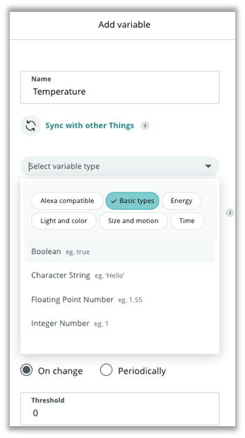
Step 2 - Variables
The second step is to add the Variables:
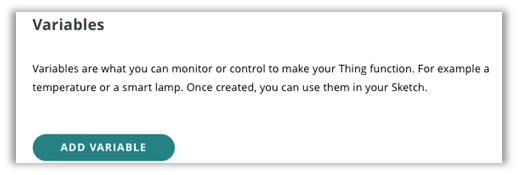
Once you click to add a variable, you need to select the variable name, type, permission, update policy and threshold. In this project 5 variables were created:
- Humidity – to store and display the relative humidity value on the dashboard
- Temperature – to store and display the room temperature on the dashboard
- msg_Attendance – to display the student attendance, name and time
- msgTempHum – to display the temperature and humidity and any warnings
- led – this LED was used for quick troubleshooting to check board/cloud connection
The variable permission can be:
- Read & Write –variable can work both as input and output, the data can be sent from the device to the cloud and vice versa
- Read only –variable can work only as output, the data can be sent only from the device to the cloud
The variable update policy can be:
- On Change: the variable will be updated to the cloud whenever the change in value is greater than or equal to the set threshold
- Periodically: the variable will be updated to the cloud each time the number of seconds set is elapsed
The basic variable types used in this project were:
- Boolean – true or false (LED)
- Floating point number – Numbers with decimals (temperature and humidity)
- Character String - words and sentences (msg_Attendance and msgTempHum)
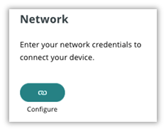
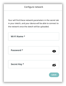
Step 3 - Network
After setting up all variables, the third step is to add network credentials in the configure Network
In this project we used the Arduino SIM card that has credentials as shown:
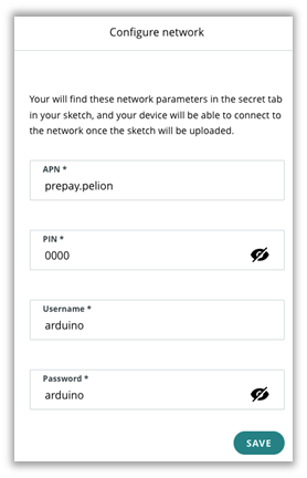
In case you are using a Wi-Fi device, the network configuration will be different. The local Wi-Fi name must not include spaces.
Step 4 - Sketch
A small part of the code is automatically updated by Arduino IoT Cloud based on the information added in the first three steps. You can can edit the sketch, the full code is shown at the bottom of this page.
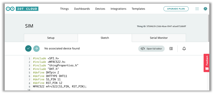
Check the Serial Monitor tab for troubleshooting your connection. If not connecting to the cloud, I recommend to use the local Arduino IDE in your computer and check the messages on the Serial Monitor.
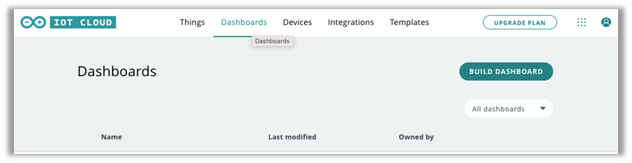
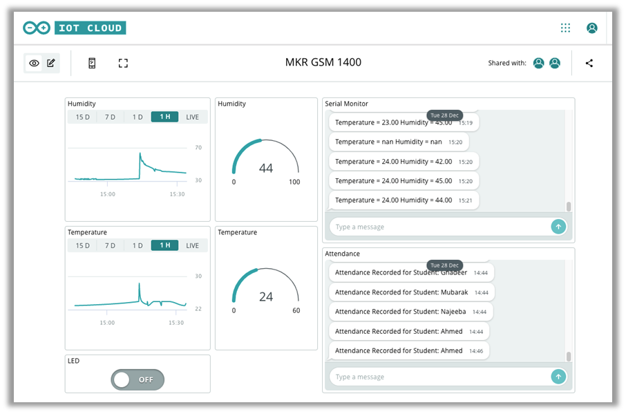
Step 5 - Dashboard
The dashboard is the last part of the IoT Cloud setup and we can click to build a dashboard in the Dashboards Tab:
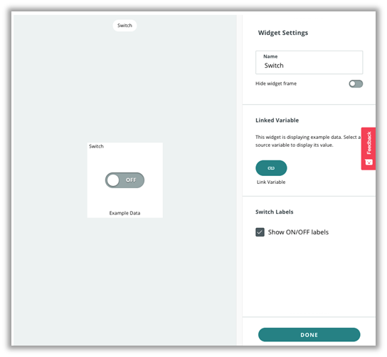
To populate our dashboard, we need to add widgets.
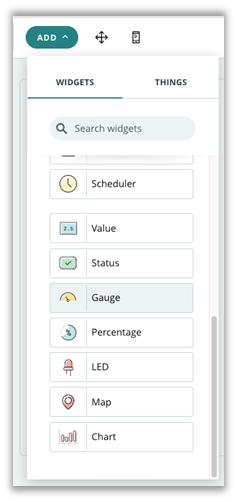
Then we link a variable to the widget in settings. In this project we added seven widgets, LED button, Humidity and Temperature gauges, Humidity and Temperature charts, temperature and humidity message and attendance message.
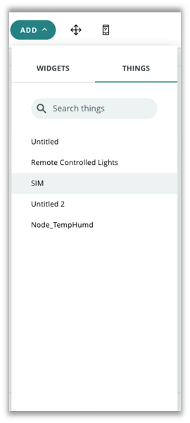
An other way of doing the steps above is to add a thing (this project Thing is called SIM):
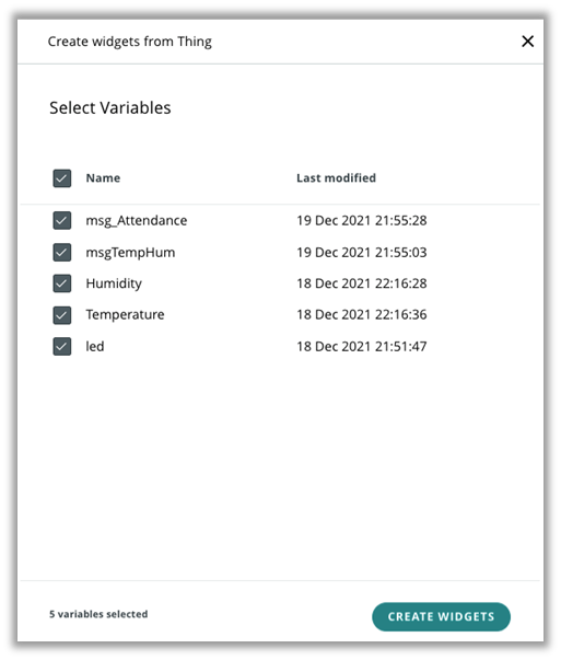
And then select the variables from Thing:
There are two type of dashboard views: the mobile view
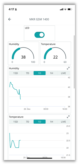
And Desktop view:
Step 6 - Download Historic Data
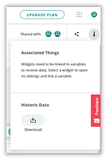
The data can be exported from the cloud using the Download Historic Data option at the dashboard (i).
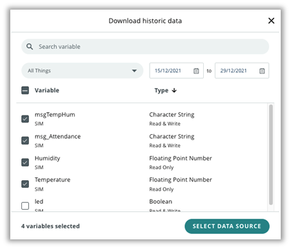
The download historic data has the option of selecting which variables we want to download, and the period.
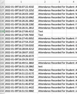
You can see an example of the attendance data that was received by email and downloaded as CSV file.
The readme.txt file contains the variable names, period requested and a message wishing us to “Have fun!”:
![Read