One of the motivations behind this project is to show that you can use your Arduino board and components from your electronics kit to make a smart lamp. This will also help you with being energy efficient and reducing your carbon footprint. Let's get started.
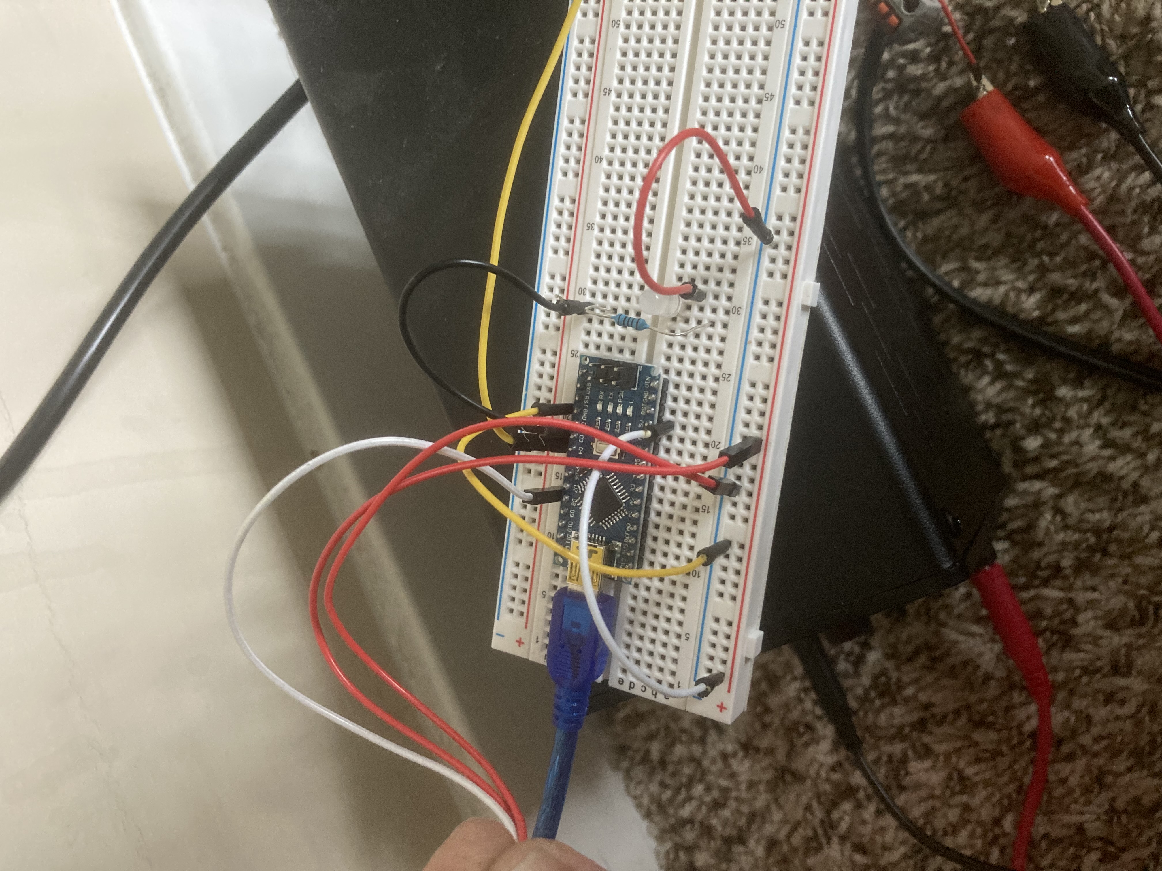
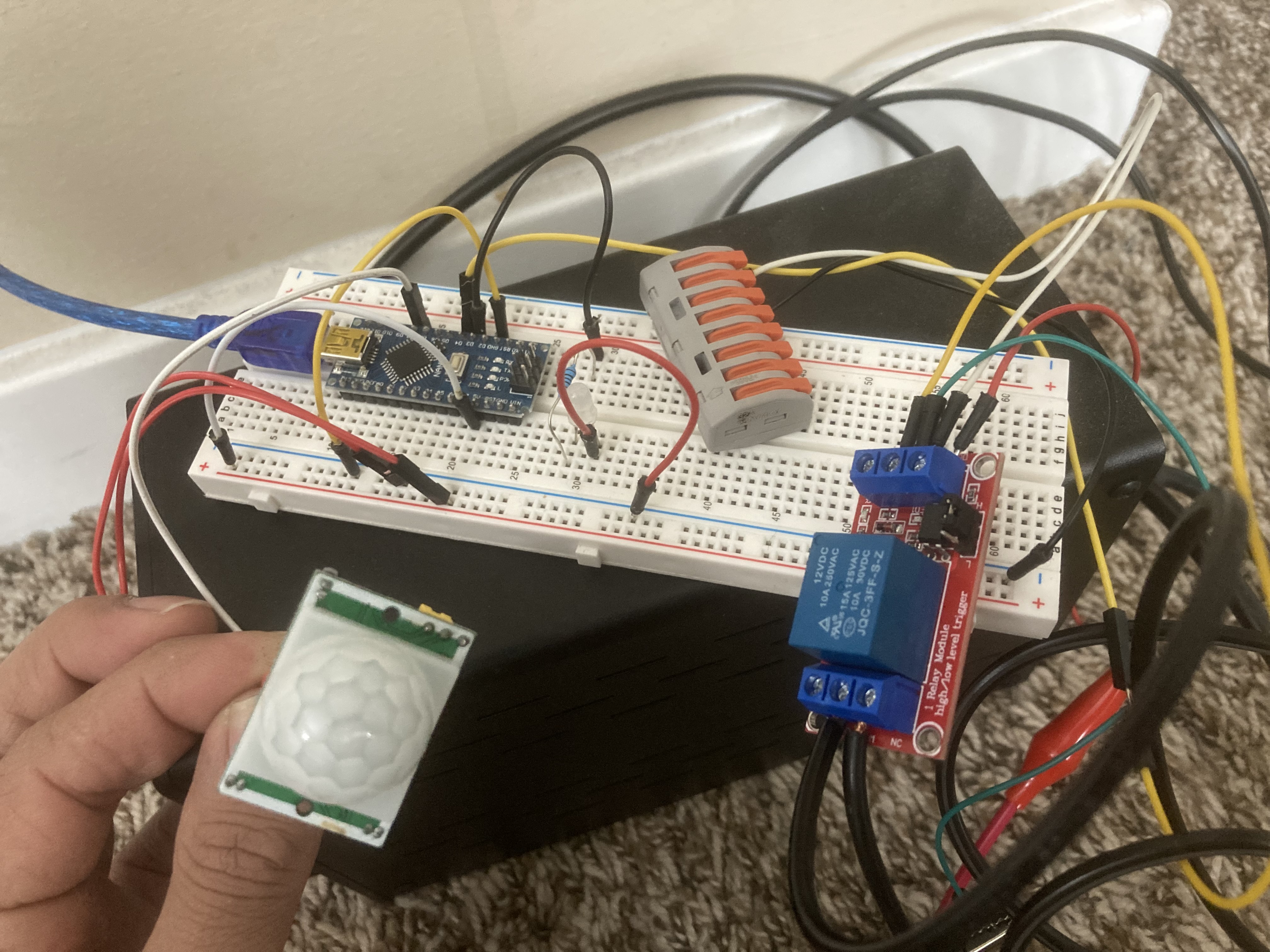
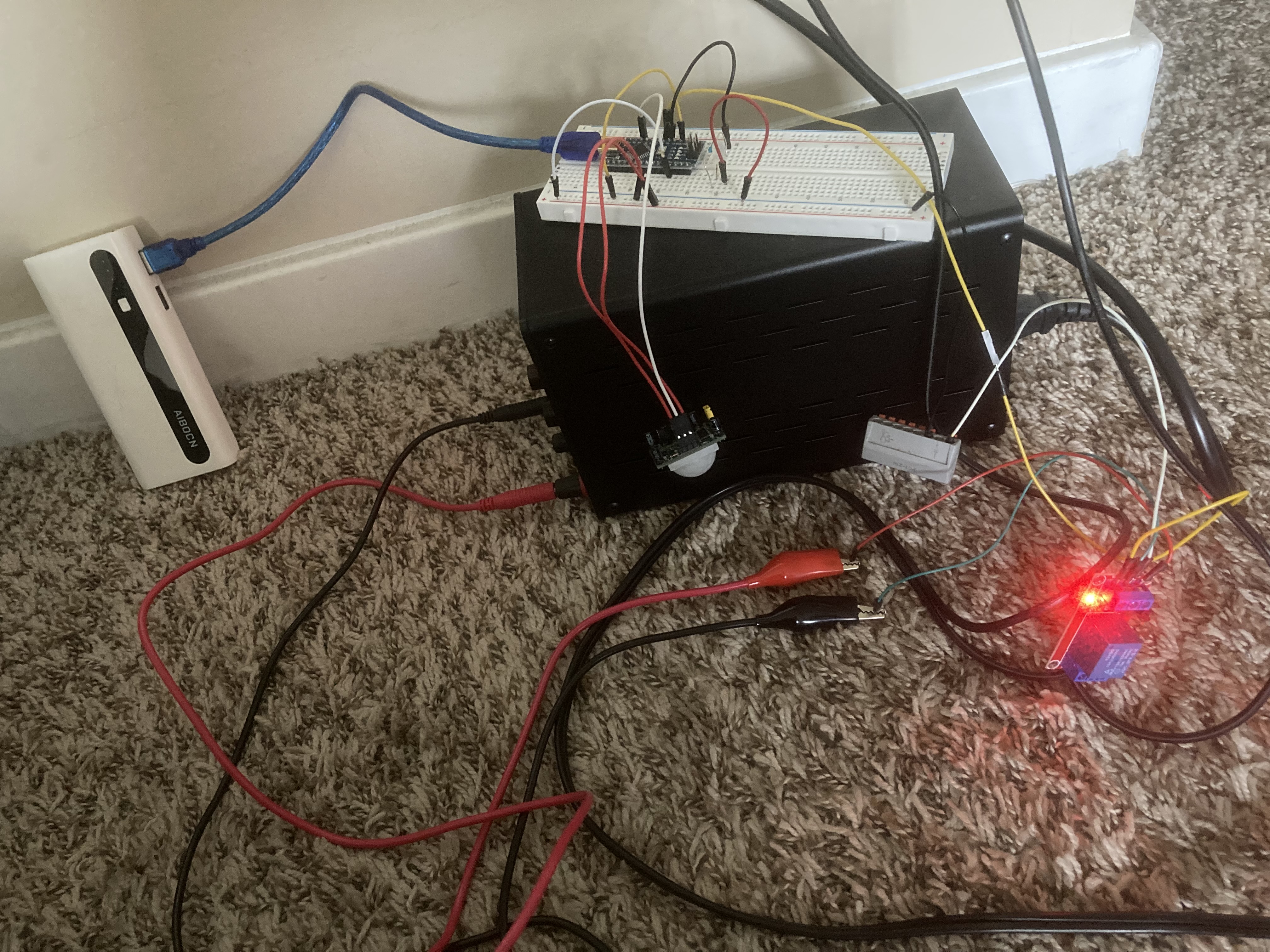
Following pictures should give you the basic idea about most of the connections:
Project Perspective
This project is the fundamental and innovative "Hello World" of smart home renovation. By focusing on the essential building blocks—a single-channel relay and an Arduino—you'll learn how to automate traditional household items using specialized software logic and a robust high-voltage setup.
Technical Implementation: Relays and Wireless Commands
The project reveals the hidden layers of simple app-to-power interaction:
- Identification layer: The relay module acts as an electronic switch, allowing your low-power microcontroller to safely control 110V/220V AC household appliances.
- Conversion layer: The Arduino uses digital output pins to send a high-low pulse to the relay, opening or closing the AC circuit.
- Wireless Interface layer: If using an ESP8266 or ESP32, the lamp can connect to the internet and be commanded via a smartphone app (like Blynk).
- Processing Logic layer: The Arduino code follows a specialized "sequential decoding" strategy: it performs "ON" or "OFF" commands for the floor lamp based on sensor input or app commands.
- Communication layer: Data is sent rhythmically between the app and the Arduino to coordinate the lamp's status in real-time.
Hardware Infrastructure
- Arduino Nano/Uno (or ESP): The "brain" of the project, managing the sensor input, serial communication, and coordinating the relay tasks.
- 5V/12V Relay Module: Effectively handles the high current and power needed for the floor lamp while protecting the microcontroller.
- PIR Motion Sensor: Detects movement to trigger the lamp automatically.
- Floor Lamp: The appliance being controlled, providing visual feedback.
- AC Power Cord: Provides the primary electrical power for the lamp.
- Micro-USB Cable: Used to program the Arduino/ESP and provide primary 5V power for the controller.
- Breadboard: A convenient way to prototype the smart circuit and connect all components securely.
Connections (step by step):
- Connect Arduino Nano on the breadboard and establish common rails for +5V and ground.
- Next connect PIR motion sensor. 1st pin is Ground. Middle pin is signal pin (connect to any digital pin). Last pin is +5V.
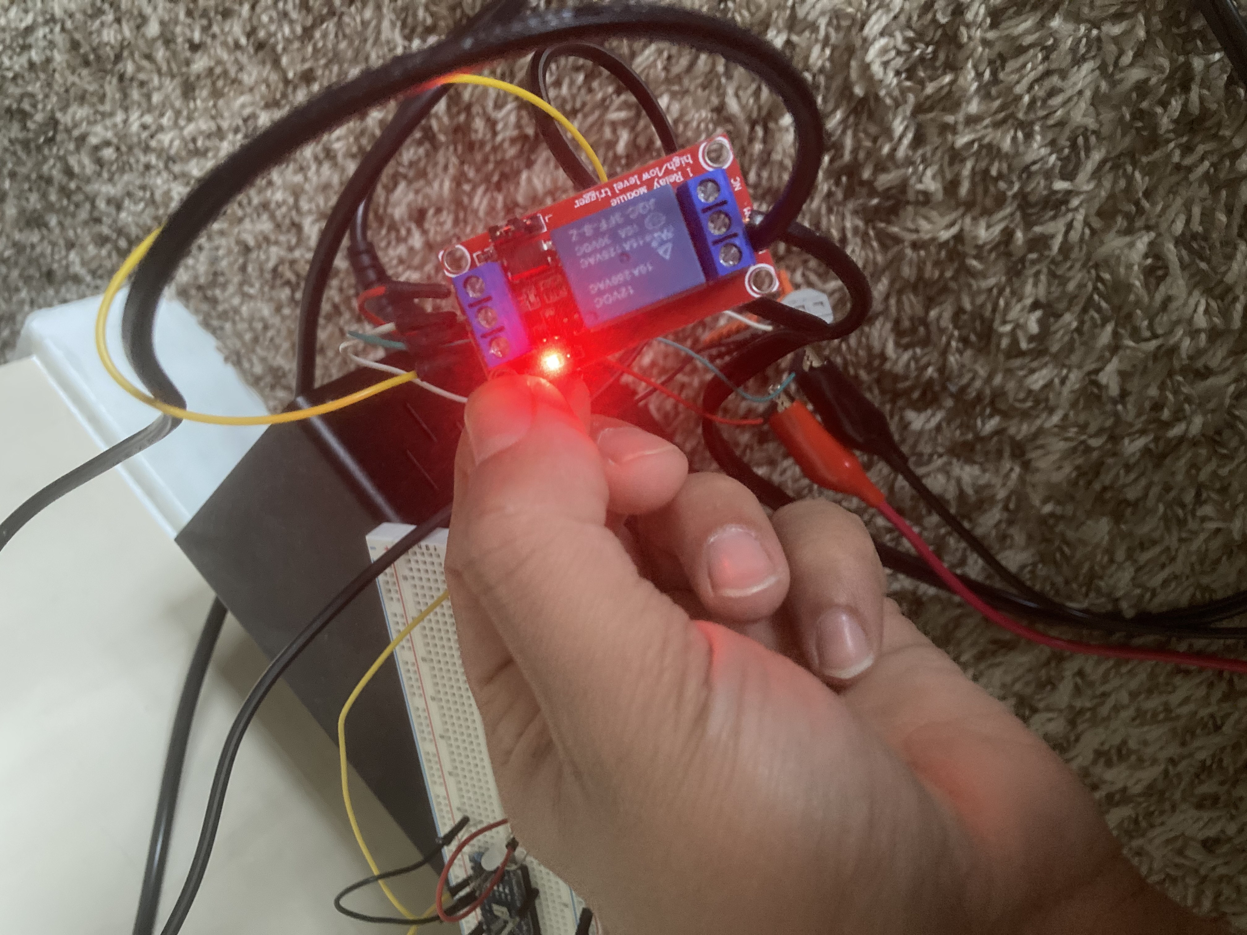
- I used a 12VDC relay module for this project this means you need 12Volts supply to make the relay work. Although a 5VDC relay could also be used.
Relay module connections: Connect external 12volts to +DC and -DC to ground. (Make sure negative DC is also connected to arduino's ground otherwise you will have problems.) .IN pin on the relay module will connect to digital Pin. Since lamp consists of 2 wires, cut 1 wire in half and connect 1 end to NO (normally open) and connect other end to COM (common).
Automation and Interaction
The smart lamp conversion process is designed to be very efficient. The core logic, as shown in the code below, initializes the hardware and then enters a loop where it waits for motion sensor input, updating the relay and lamp status in real-time.
I came up with the following code.
int motionPin=8; // PIR signal pin
int val=0;
int pirState=LOW;
int ledPin=3;
int relayPin=4; // IN pin on relay Module

void setup() {
// put your setup code here, to run once:
pinMode(motionPin,INPUT);
pinMode(ledPin,OUTPUT);
pinMode(relayPin,OUTPUT);
Serial.begin(9600);
}

void loop() {
// put your main code here, to run repeatedly:
val=digitalRead(motionPin);
if (val==HIGH)
{
if (pirState==LOW){
Serial.println(" MOTION DETECTED");
digitalWrite(ledPin,HIGH);
digitalWrite(relayPin,HIGH);
pirState=HIGH;

}
}
else
if (pirState==HIGH)
{
Serial.println(" MOTION ENDED");
digitalWrite(ledPin,LOW);
digitalWrite(relayPin,LOW);
pirState=LOW;

}
}
Future Expansion
- OLED Identity Dashboard Integration: Add a small OLED display on the lamp enclosure to show "Connection Status" and "Power Usage" (kWh).
- Multi-sensor Climate Sync: Connect an LDR (light sensor) to have your floor lamp "Turn ON" automatically at sunset.
- Cloud Interface Registration Support: Add a WiFi module (ESP8266/ESP32) and link to a cloud dashboard to precisely track and log the lamp history from a smartphone wirelessly over WiFi.
- Advanced Velocity Profile Customization: Add specialized "Voice Control" (Alexa/Google Home) to have the lamp follow your spoken commands.
Basic floor lamp to SMART floor lamp!!!!! is a perfect project for any electronics enthusiast looking for a more interactive and engaging smart home tool!