Connections
1). Relay to Arduino Connection
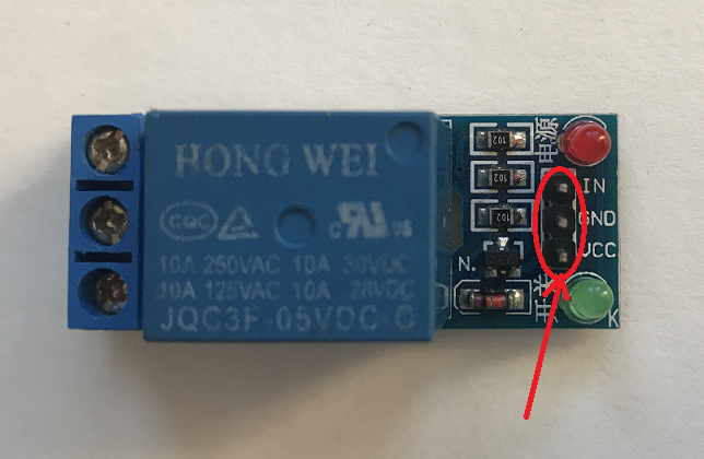
- Connect the Vcc pin of Relay to Arduino 5V
- Connect the GND pin of Relay to Arduino GND
- Connect the IN pin(Input pin) of Relay to Arduino digital pin D3
2). Relay to LED connection
The relay module has 3pin screw terminal.
a). NO - Normally open
b). COM - Common
c). NC - Normally closed
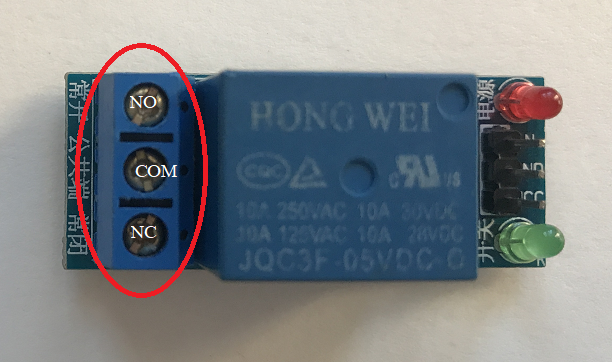
High voltage connections can be made to this screw terminal. For example: Bulb, ceiling fan etc., But in this project we are just using an LED.
When you make the connection between a) and b), the connected LED is always ON until it receives a signal from the Arduino to turn it OFF.
When you make the connection between b) and c), the connected LED is OFF until it receives a signal from the Arduino to turn it ON.
I have used breadboard to make connections easier. See the circuit diagram to understand better!
End Result
EXPANDED TECHNICAL DETAILS
Electrical Isolation Fundamentals
This foundational project teaches how to safely bridge the gap between low-voltage 5V electronics and high-voltage AC mains appliances.
- Opto-Isolation Hub: The relay module features an onboard optocoupler (PC817) that electrically separates the Arduino from the 220V/110V load. This prevents back-EMF or high-voltage failures from damaging the microcontroller.
- Switching Logic: The Arduino provides a digital HIGH or LOW to the relay "Signal" pin, which activates an internal electromagnet to physically flip a mechanical switch.
Safety Precautions
- Terminal Block Management: Explains the difference between NO (Normally Open) and NC (Normally Closed) connections, allowing for fail-safe configurations where the appliance default is OFF during a power loss.