First, I would like to thank all the Frontliners who are risking their lives everyday and I hope you guys are all doing OK [Yes, you too] despite the pandemic.
Welcome to Part 2 of the Bike Turn Signal Project Series.
This video would mostly consist small code changes and power draw tests.
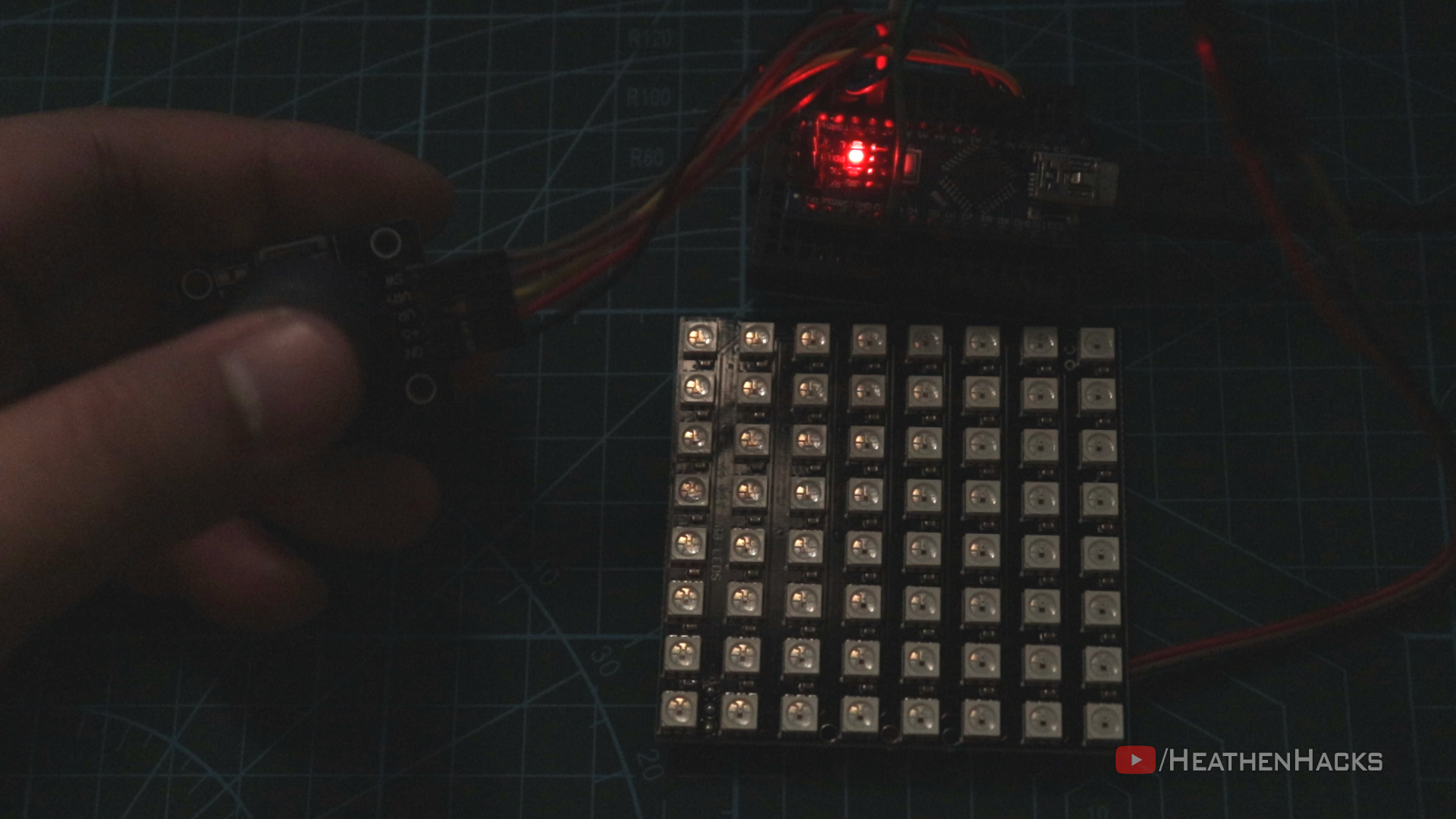
I received the new pair of WS2812B matrices as replacement for the broken ones a few days before making the video.
I initially tried to use delays for the "blink" effect and opted to use FastLED's EVERY_N_MILLISECONDS instead.
On this project, I would still use the same ArduinoNANO, 8x8 RGB LED Matrix and PS2 Joystick Module.
I would also use my DIY Powerbank for the power source.
Project Perspective
The Bike Turn Signal - Part 2 is a practical and fun layout for any cyclist to improve their safety. By utilizing two LED arrays and two push buttons, you can signal your turns clearly and intuitively.
Technical Implementation
The Arduino Nano's built-in digital inputs and outputs are used to read signals from the PS2 joystick module and control the WS2812B LED matrices. The code uses digitalRead() to check the state of the joystick's directional switches. When a left or right input is detected, the code triggers a blinking sequence on the corresponding LED matrix using the FastLED library's EVERY_N_MILLISECONDS function for non-blocking timing, a significant improvement over using delay().
Hardware Infrastructure
- Arduino Nano: The primary controller for the turn signal system.
- PS2 Joystick Module: Used to activate either the left or right turn signal.
- WS2812B 8x8 LED Matrices: Provides the visual signals for turning.
- DIY Powerbank: Powers the entire system portably.
Signal Transmission and Logic
The Arduino code monitors the joystick's X-axis. When the joystick is pushed left or right, it triggers a specific, customizable blinking pattern on the corresponding LED matrix. The use of non-blocking timers ensures the system remains responsive and allows for smooth animation effects.
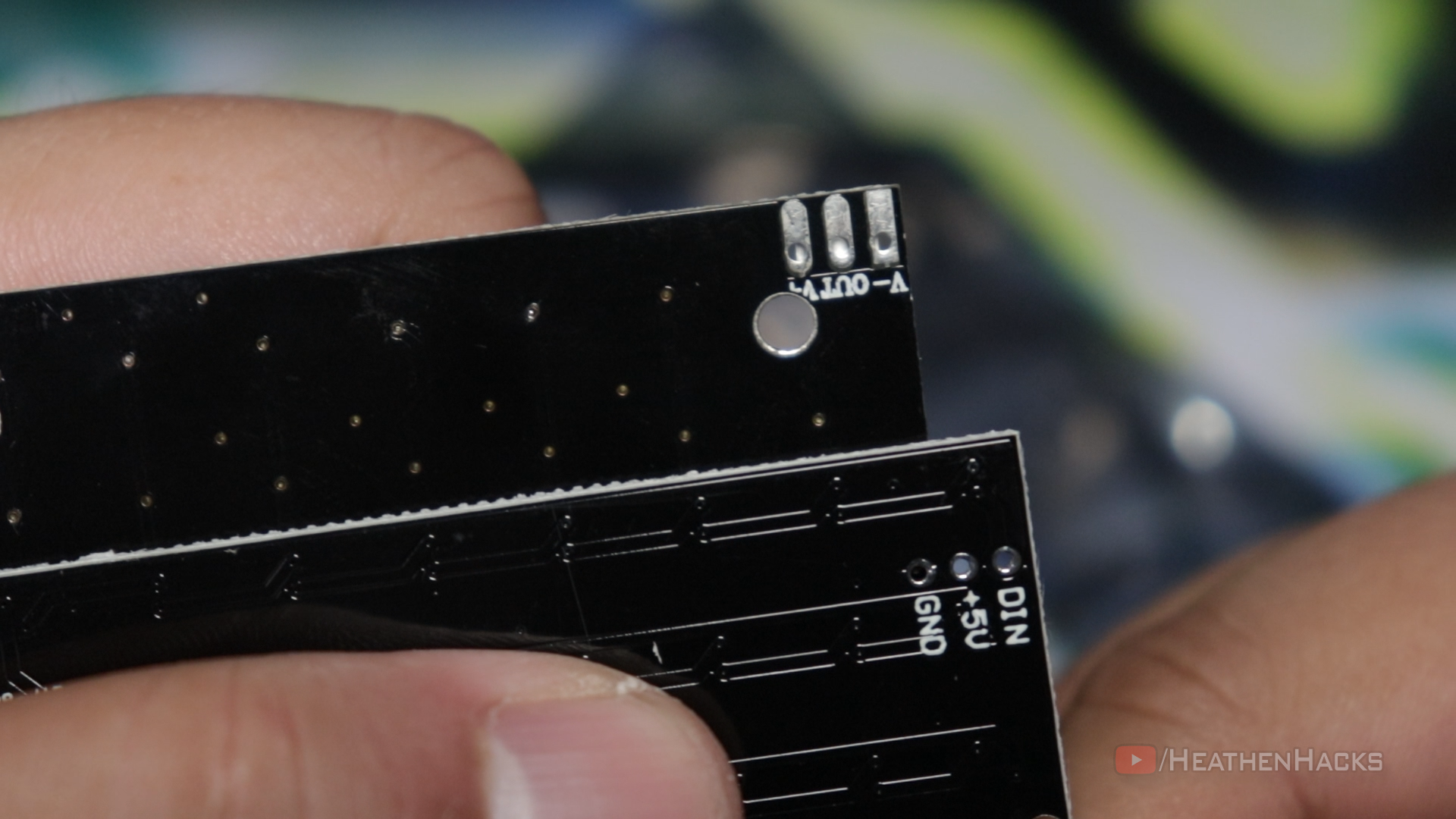 Difference between the old matrix and the "new" one
Display and Control
The LED matrices are mounted to provide a clear left/right configuration, creating a highly visible signal for other road users. The joystick offers an intuitive, thumb-operated control interface that can be easily integrated onto handlebars.
Future Expansion
- Wireless Signal: Use a Bluetooth or RF module to trigger the turn signal from a smartphone or a handle-mounted remote.
- Automatic Braking Integration: Integrate with a brake light system for increased visibility.
- Daylight Running Lights: Add a setting for constant, dimmed illumination of the LED matrices for improved visibility during the day.
- Audio Feedback Integration: Add a piezo buzzer or speaker for audible turn signal confirmation.