Beside programming arduino in CC+, I also have some skills to program in Visual Basic 6.
Some years ago I made a program to show the time in ledbars, See photo:
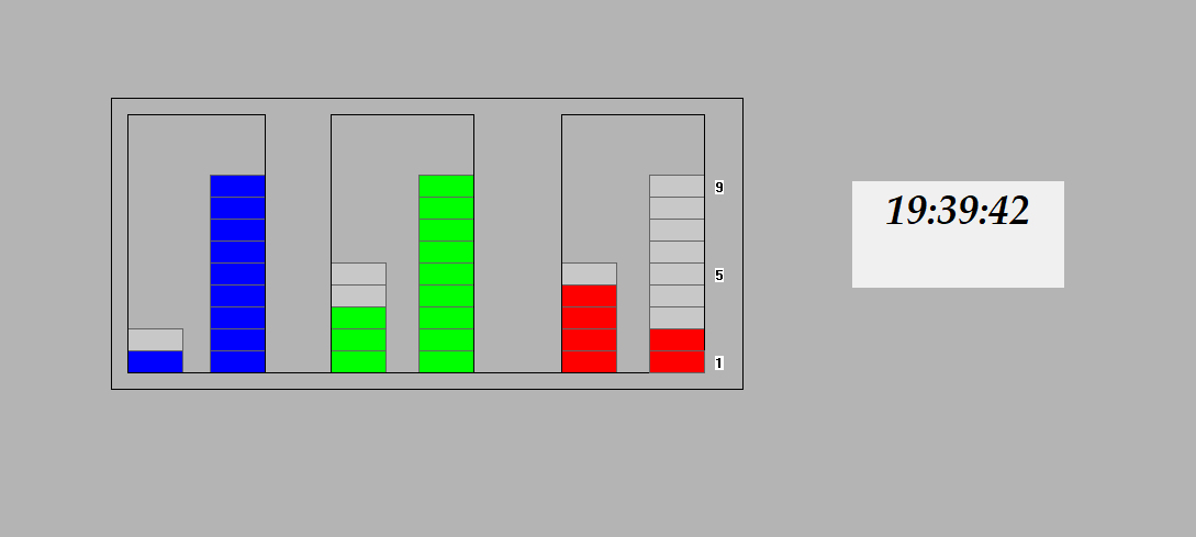
As you can see, the hour is 19, the blue leds represents this in 1 led and 9 leds,
also the minutes 39 : 3 and 9 green leds, and the seconds 42: 4 and 2 red leds.
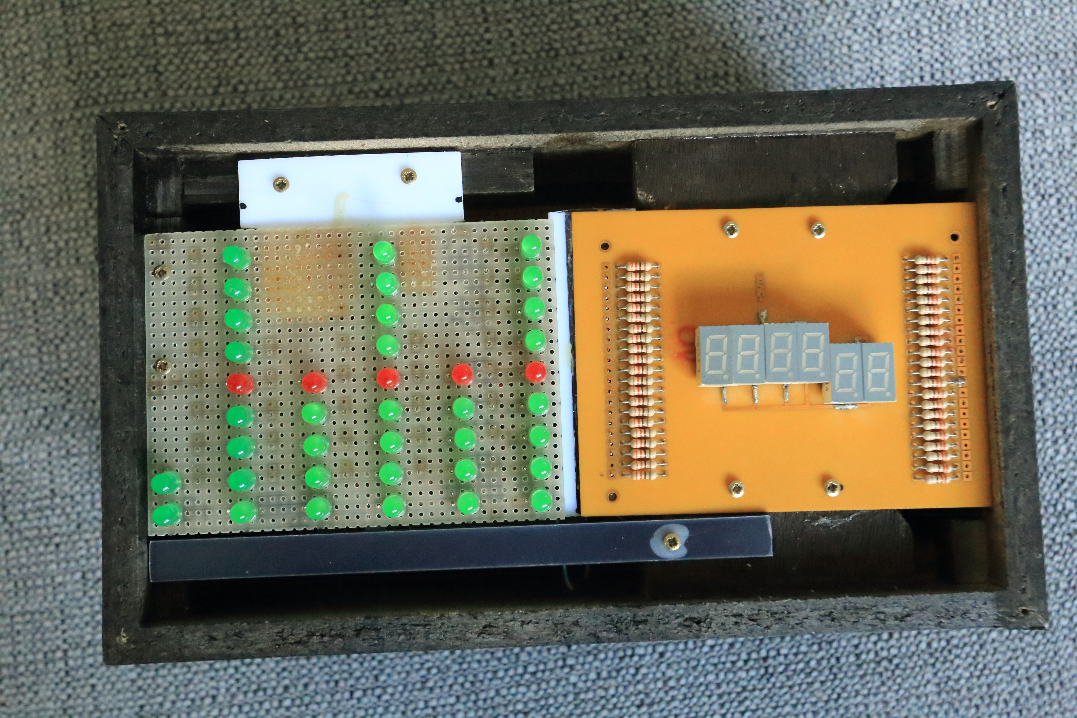
So I made this clock with a few more functions.
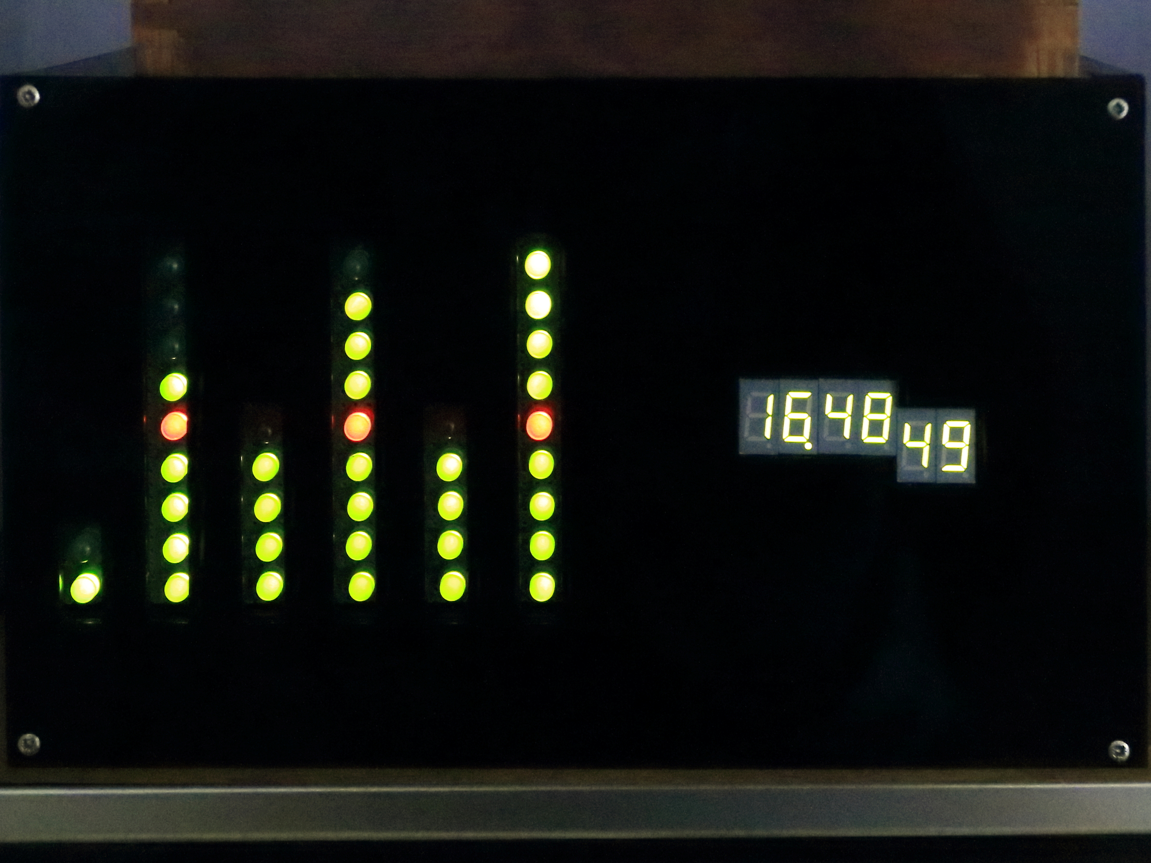
As you can see it is the same look: the hours are the two left bars (1 and 6 leds are lit), the minutes are the bar 3 and 4 (4 and 8 leds are lit), and the seconds are the two right bars (4 and 9 leds are lit).
The 5th led in every column (except the first) are red,
See photo:

Project Perspective
This binary/decimal clock is an innovative "Logic Trainer" that bridges fundamental electronics concepts with modern development. By focusing on essential building blocks like bit-manipulation arithmetic and hardware interfacing, you'll learn to automate time-keeping using specialized software logic and a robust hardware setup.
Technical Implementation: Bit-arithmetic and Matrix Driving
The project reveals the hidden layers of simple binary-to-light interaction, built on several key layers:
- Identification layer: The DS3231 RTC Module acts as a high-resolution temporal reference, providing the exact time via its internal crystal.
- Processing Logic layer: The Arduino code follows a "bit-weighting" (decimal-to-binary) strategy. It interprets the RTC values and matches the LED states to provide safe and rhythmic clock patterns. The core logic involves extracting binary digits from time values to control the LED columns.
- Visual Interface layer: The LED bars and 7-segment displays provide clear visual feedback for the "Time Status" (e.g., Columns = Hours/Minutes/Seconds in Decimal or Binary).
- Communication & Control layer: The system uses shift registers (SN74595) to manage a large number of LEDs and display segments efficiently. The LEDs are controlled via multiplexing, while the displays are not, as shown in the schematics and gallery photos above.
[!TIP] In your Arduino code, use the
bitRead()function to easily extract the binary status for each LED column without complex division math!
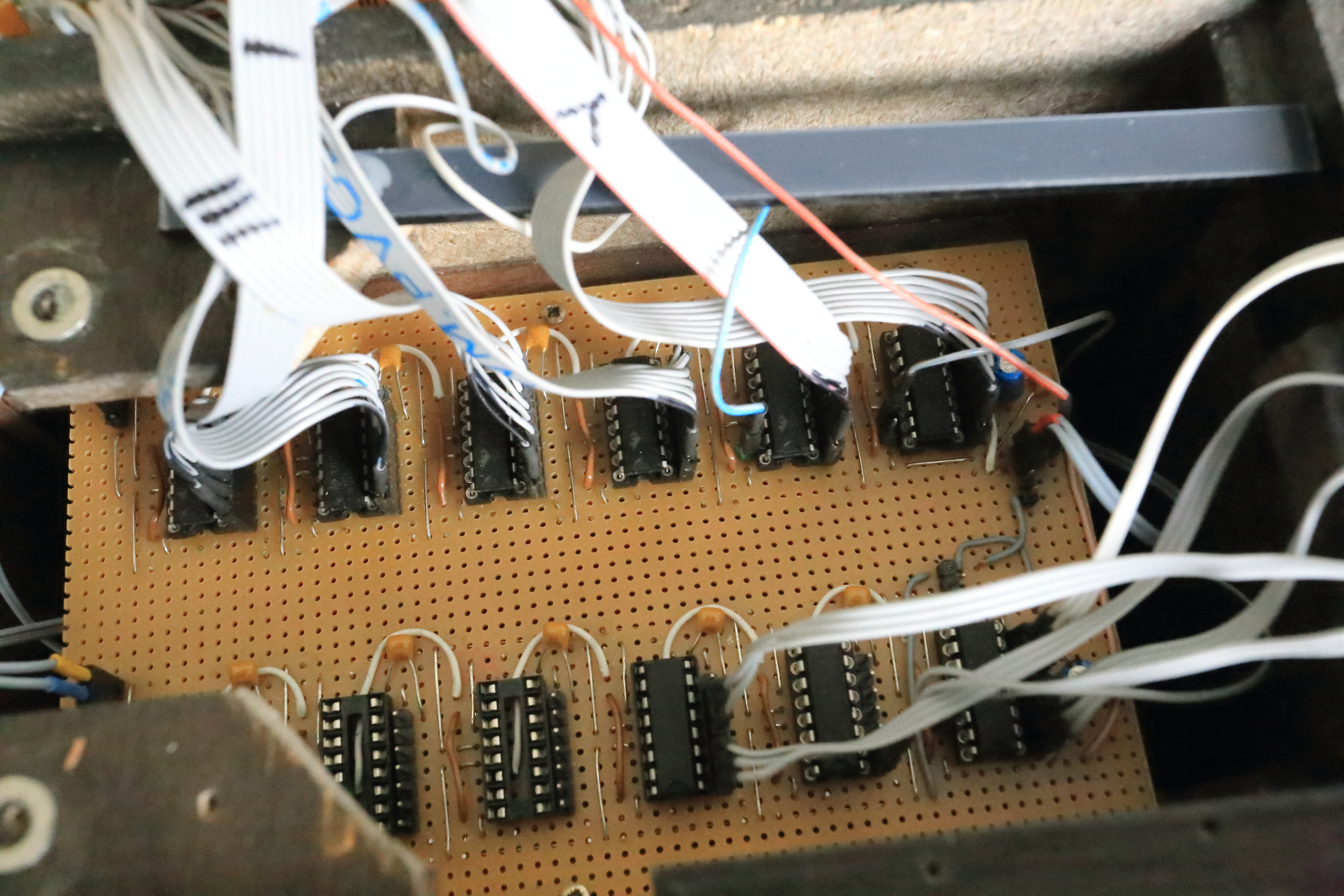
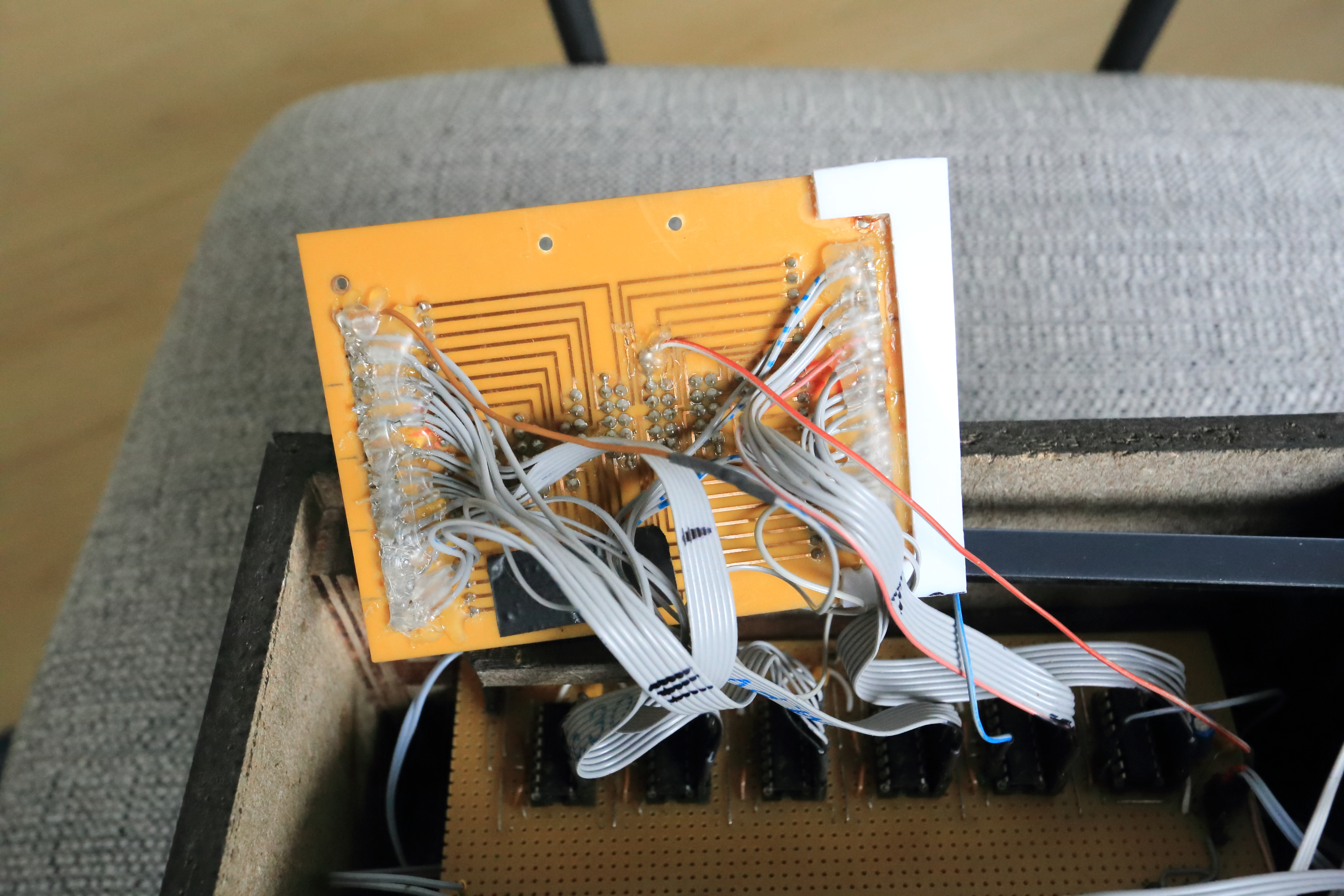
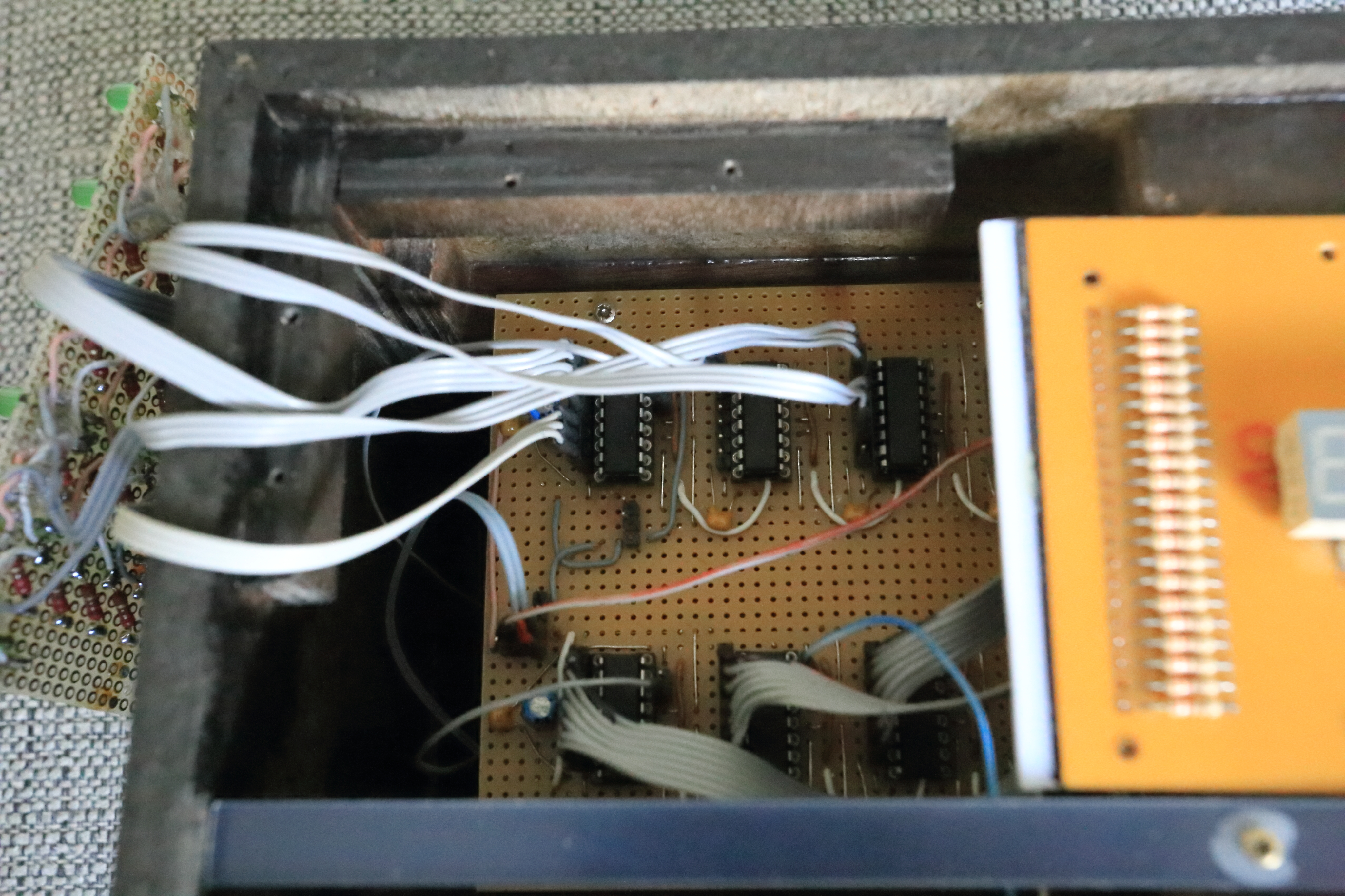
Hardware-Timepiece Infrastructure
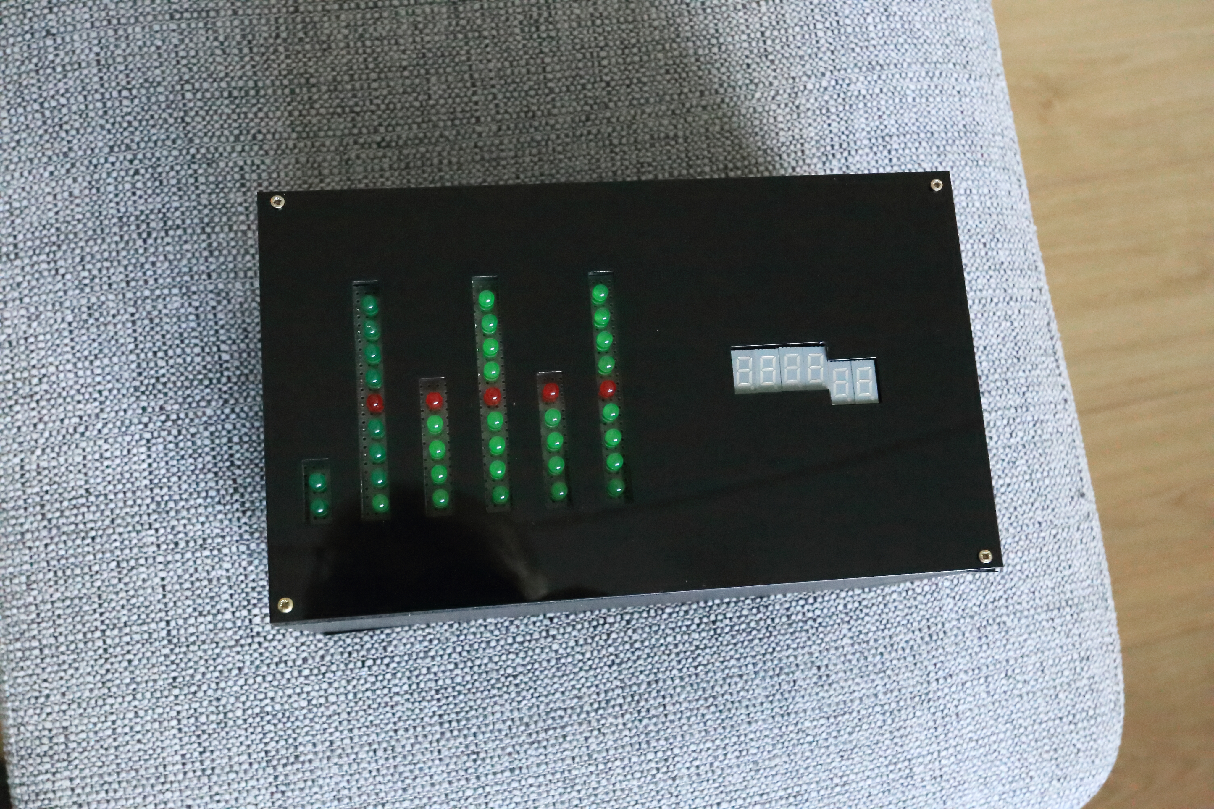
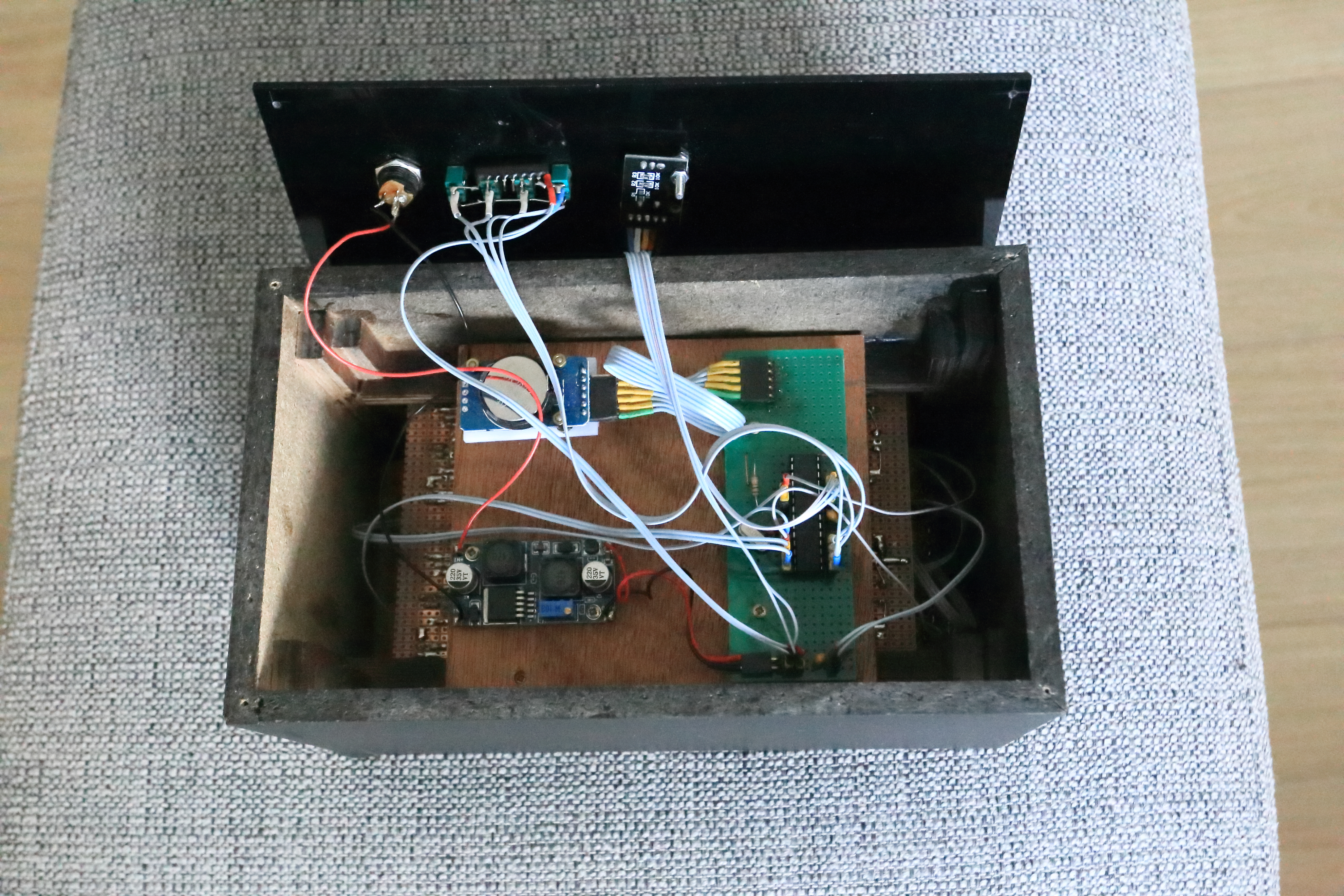
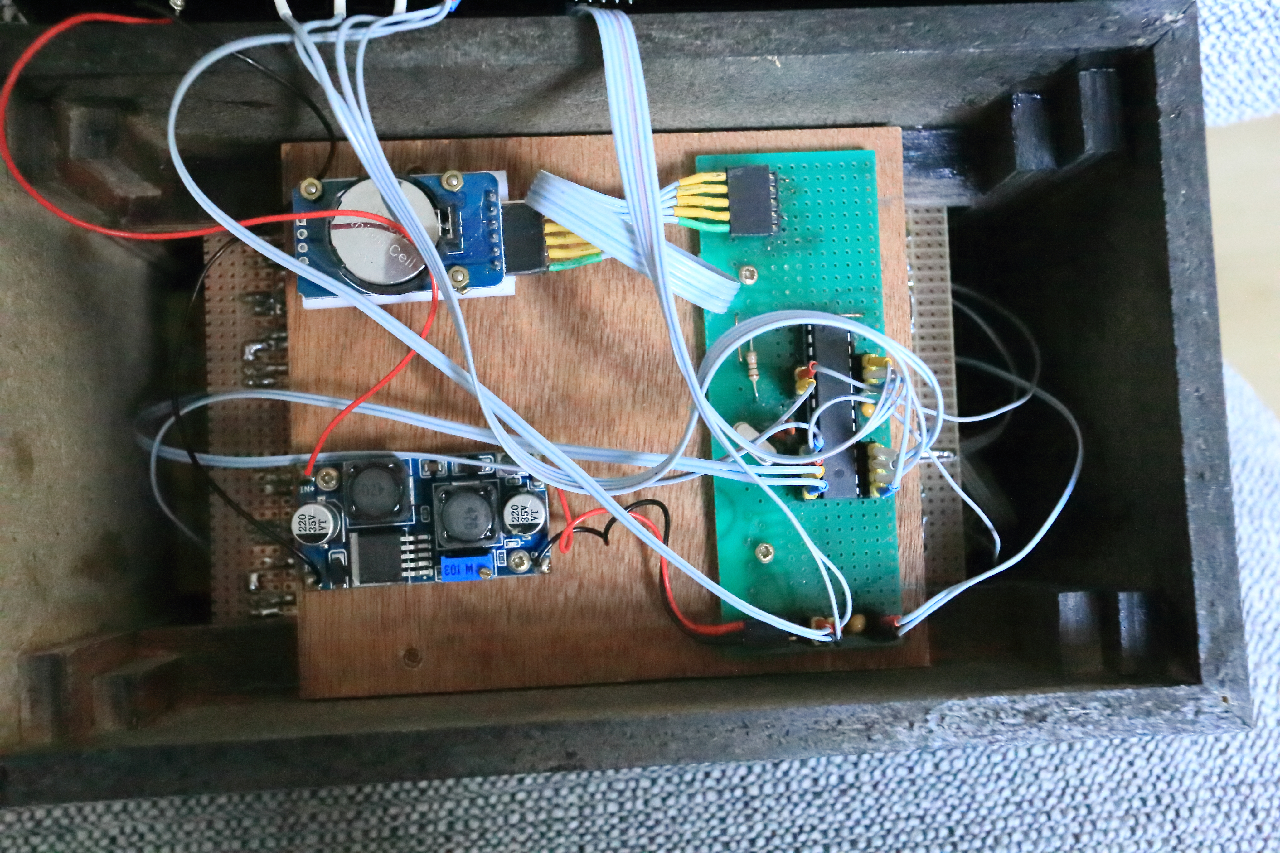
The physical build consists of several key components, visible in the project gallery:
- ATmega328 (Arduino-compatible): The "brain" of the project, managing time calculation, mode switching, and coordinating the shift registers.
- SN74595 Shift Registers: Nine in total (six for the 7-segment displays, three for the LED bars) are used to expand the number of outputs and control all indicators.
- DS3231 RTC: Provides high-capacity and reliable time-keeping.
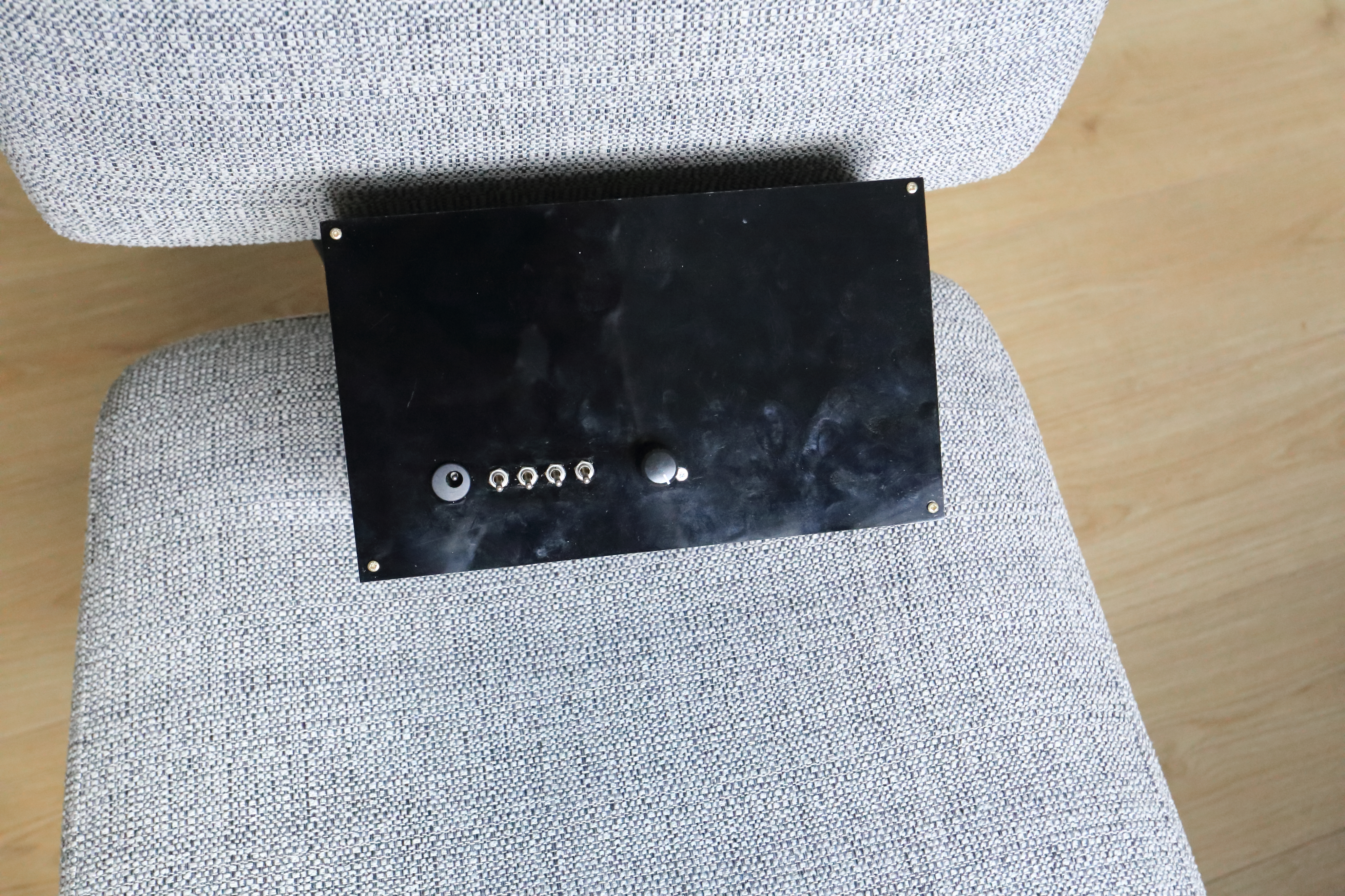
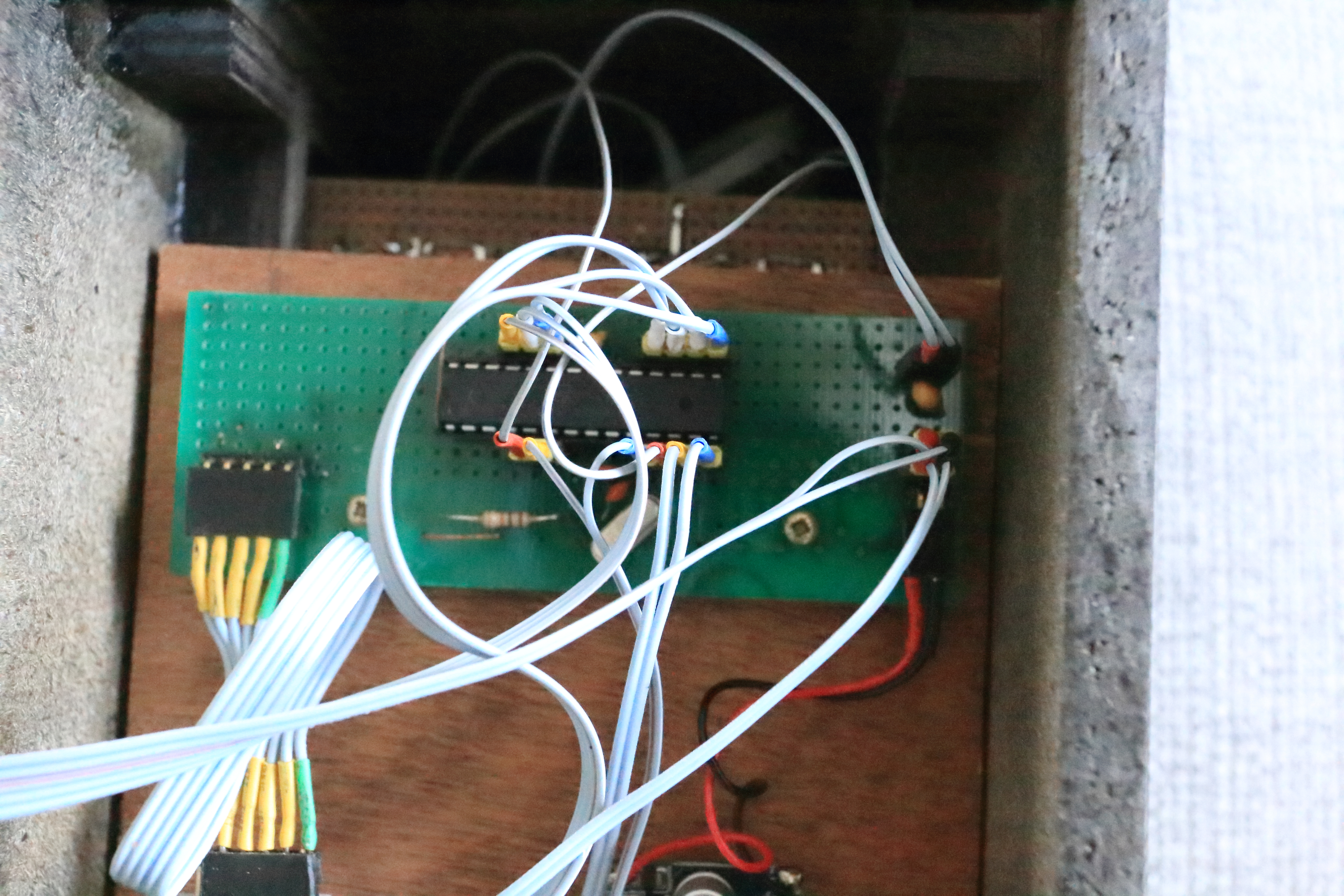
- Custom PCB/Breadboard: A structured way to connect all components, as seen in the rear-view images.
Clock Automation and Interaction
The clock's operation is centered around four switches, providing 16 different functions. The main loop constantly checks the state of these switches to determine the active mode.
Primary Functions:
- Function 0000: LEDs show time in decimal format; Display shows time.
- Function 0001: LEDs show time in decimal format (barmode); Display shows date.
- Function 0010: LEDs show time—each column in binary format; Display shows time.
- Function 0100: LEDs blank; Display shows time (with night mode blanking between 0-8 AM).
- Function 1001: LEDs blank; Display shows adjustment menu for time, date, and RTC.
- Function 1100/1101/1110/1111: LEDs show time; Display shows sun position data (rise, set, max elevation, current elevation) for a set latitude.
Code Explanation
The main loop uses a switch statement based on the switch positions (Test).
switch (Test) {
  case 0:// 0000
    if (ddd[0] == 1) {
      Tijd();        // Update LED bars for time
      dddInstellen(0);
    }
    TijdDig1();      // Update 7-segment display for time
    break;
When the switch position = 0, this part of the routine is valid. The if statement prevents the LEDs from flickering; the Tijd() routine runs only once per update cycle, while the display routine TijdDig1() runs as often as needed. dddInstellen(0) resets the flag variable ddd[0] to 0. This flag is set back to 1 once per second by an interrupt to allow the display to update.
The 1-Second Interrupt:
if (secondsInterrupt == 1) { // Triggered by 1 Hz SQW from the RTC on interrupt pin 2
  readtime();                // Read the time from the RTC
  secondsInterrupt = 0;      // Reset ISR flag
  dddInstellen(16);          // Reset the ddd[x] variables to 1 to enable updates
}
Efficient Display Update:
The Tijd() function demonstrates efficient data handling. It uses a DDP() function to send time data to the displays in a single line.
void Tijd() { // time
  DDP(LED1[a], LED1[b], LED1[c], LED1[d], LED2[e], LED1[f]);
}
Variables a and b represent the seconds, c and d the minutes, and e and f the hours. The program looks up the corresponding segment pattern from pre-defined arrays (LED1[], LED2[]) and sends all six codes to the shift registers at once.
Historical Context & Build Notes
In the past, I built a similar clock using discrete digital ICs (BCD counters, decoders) and 48 resistors—one for each display segment. There was no RTC. The current version is greatly simplified and enhanced. I reused the original displays but now drive them with 6 shift registers. The LEDs are driven by 3 more shift registers using multiplexing. I also wrote the low-level routines to communicate with the DS3231 RTC directly, eliminating the need for an external library.
Future Expansion Ideas
- OLED Dashboard: Add a small OLED display on the back to show "Current Mode" or other status information.
- Wireless Control: Integrate a pushbutton or rotary encoder for easier mode switching and menu navigation.
- Cloud Interface: Add WiFi or Bluetooth to sync time via NTP or log time history to a web dashboard.
- Ambient Light Sensor: Implement auto-brightness adjustment for the LEDs and displays based on room lighting.
This binary/decimal clock is a perfect project for any electronics enthusiast looking for an interactive and engaging logic tool that blends hardware design with sophisticated software control.