Introduction
After I bought a new house, my first intention was to fully convert it into a Smart Home, and the most crucial starting point was automated blinds control. However, what seemed like a simple project turned into an engineering nightmare at first. The high-power motor (150W) I chose generated reverse inductive voltage that damaged both Relays and Triacs. Additionally, there were issues with line noise causing the blinds to operate on their own in the middle of the night, which was quite frightening.
Eventually, I successfully solved these problems with inexpensive electronic components. In this article, I will share the detailed solution so you don't have to waste time and endure headaches like I did. For those who aren't keen on programming but love soldering, I also have a Discrete circuit (without a Microcontroller) at the end that works similarly.
In-depth Problem Analysis and Engineering Design
1. Handling Inductive Electrical Loads
The major problem with motor control is "Inductance." When we try to open the circuit while the motor is running, the current attempts to continue flowing due to the residual magnetic field, causing a sudden high voltage (Back EMF).
From oscilloscope measurements, I found peak voltages exceeding 1600V. Such a voltage:
- If using small Relays: Contacts will spark severely and stick together.
- If using Triacs (Solid State Relay): The overvoltage will instantly destroy the semiconductor material inside.
2. Circuit Protection Solution
Instead of using expensive, large Relays, I opted for "engineering" solutions by adding just a few components to the circuit:
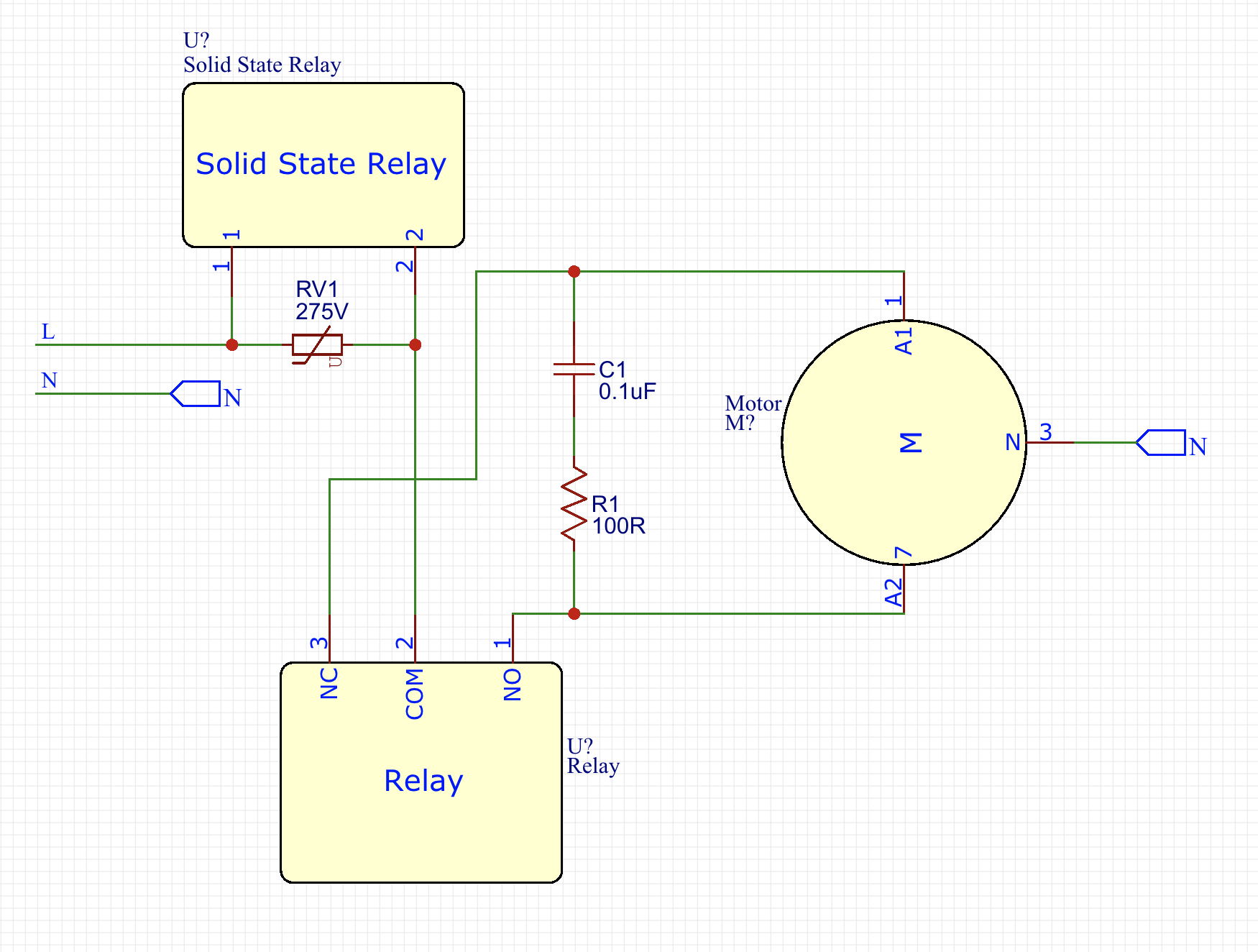
- Varistor (MOV): Acts as a clamping device to protect the Triac from Over-voltage.
- RC Snubber Circuit (Resistor + Capacitor): Absorbs energy generated during circuit switching (Commutation), helping to reduce the rate of voltage rise ($dv/dt$).
Technical Recommendation: From actual experimentation, I found that installing the RC Snubber assembly between the brown and gray wires of the motor (as per the diagram) yielded the best results. This is because the Snubber assembly is not constantly connected to the main line, which increases safety and lifespan.
Software Code Logic
To maximize system robustness, I designed a systematic operating sequence for the Arduino using a Hybrid Switching technique:
- Reducing Pin Count: I used a common wire for up/down commands, allowing control of 4 motors using only 5 Input pins (instead of 8), along with a software Debounce system to prevent noise.
- Power-on Sequence:
- Arduino first opens the Relay to select the direction (no current flowing yet).
- A short delay allows the relay contacts to close firmly.
- The Triac is then turned on to supply 230 VAC to the motor.
- Power-off Sequence:
- The Triac is turned off first to cut the main current.
- A delay allows the current to completely stop flowing.
- The Relay is then turned off.
- Result: The Relay experiences no sparking at all (Zero-current switching), significantly extending its lifespan.
Wireless Control System and Smart Home Integration
This system is highly scalable. If using MySensors, you can connect up to 256 Nodes, with each Node controlling 4 sets of blinds, which is sufficient even for a large mansion.
1. Connecting via Raspberry Pi
I use a Raspberry Pi as the main controller (Master), with an nRF24L01+ module and Domoticz software installed.
Precautions for Radio Modules:
- Always install a 10 µF capacitor at the VCC/GND pins of the nRF24L01+ to filter current.
- If installing in a thick wall box, choose a module with an External Antenna, as PCB antennas have very limited transmission range.
2. MySensors MQTT Gateway Setup
If you choose to use MySensors, you can set it up on a Raspberry Pi with the command:
sudo ./configure --my-gateway=mqtt --my-controller-ip-address=127.0.0.1 --my-mqtt-publish-topic-prefix=domoticz/in/MyMQTT --my-mqtt-subscribe-topic-prefix=domoticz/out/MyMQTT --my-mqtt-client-id=mygateway1 --my-transport=rf24 --my-port=1883 --my-rf24-irq-pin=15
3. Source Code for Raspberry Pi (C++)
This code is responsible for sending commands to the Arduino and waiting for an acknowledgment (ACK) to confirm that the blinds have operated correctly:
#include <unistd.h>
#include <string>
#include <getopt.h>
#include <cstdlib>
#include <sstream>
#include <iostream>
#include <RF24/RF24.h>
using namespace std;

RF24 radio(RPI_V2_GPIO_P1_22, RPI_V2_GPIO_P1_24, BCM2835_SPI_SPEED_8MHZ);
const uint64_t pipes[2] = { 0xF0F0F0F0E1LL, 0xF0F0F0F0D2LL };
unsigned long  got_message;

void setup(void){
	printf("Preparing interface\n");
	radio.begin();
	radio.setRetries(15, 15);
	radio.setChannel(0x70);
	radio.setDataRate(RF24_250KBPS);
	radio.setPALevel(RF24_PA_MAX);
	radio.openWritingPipe(pipes[0]);
	radio.openReadingPipe(1,pipes[1]);
}

bool sendMessage(int action){
	radio.stopListening();
	unsigned long message = action;
	printf("Now sending %lu...", message);
	bool ok = radio.write( &message, sizeof(unsigned long) );
	if (!ok) printf("failed...\n");
	else printf("ok!\n");

	radio.startListening();
	unsigned long started_waiting_at = millis();
	bool timeout = false;
	while ( ! radio.available() && ! timeout ) {
		if (millis() - started_waiting_at > 1000 ) timeout = true;
	}
	if( timeout ){
		printf("No response received...\n");
		return false;
	}else{
		radio.read( &got_message, sizeof(unsigned long) );
		printf("Response received > %lu.\n", got_message);
		return true;
	}
}
// Remaining part of the main function...
You can download the library and pre-compiled files for Raspberry Pi 3 here: https://goo.gl/ocCwk3
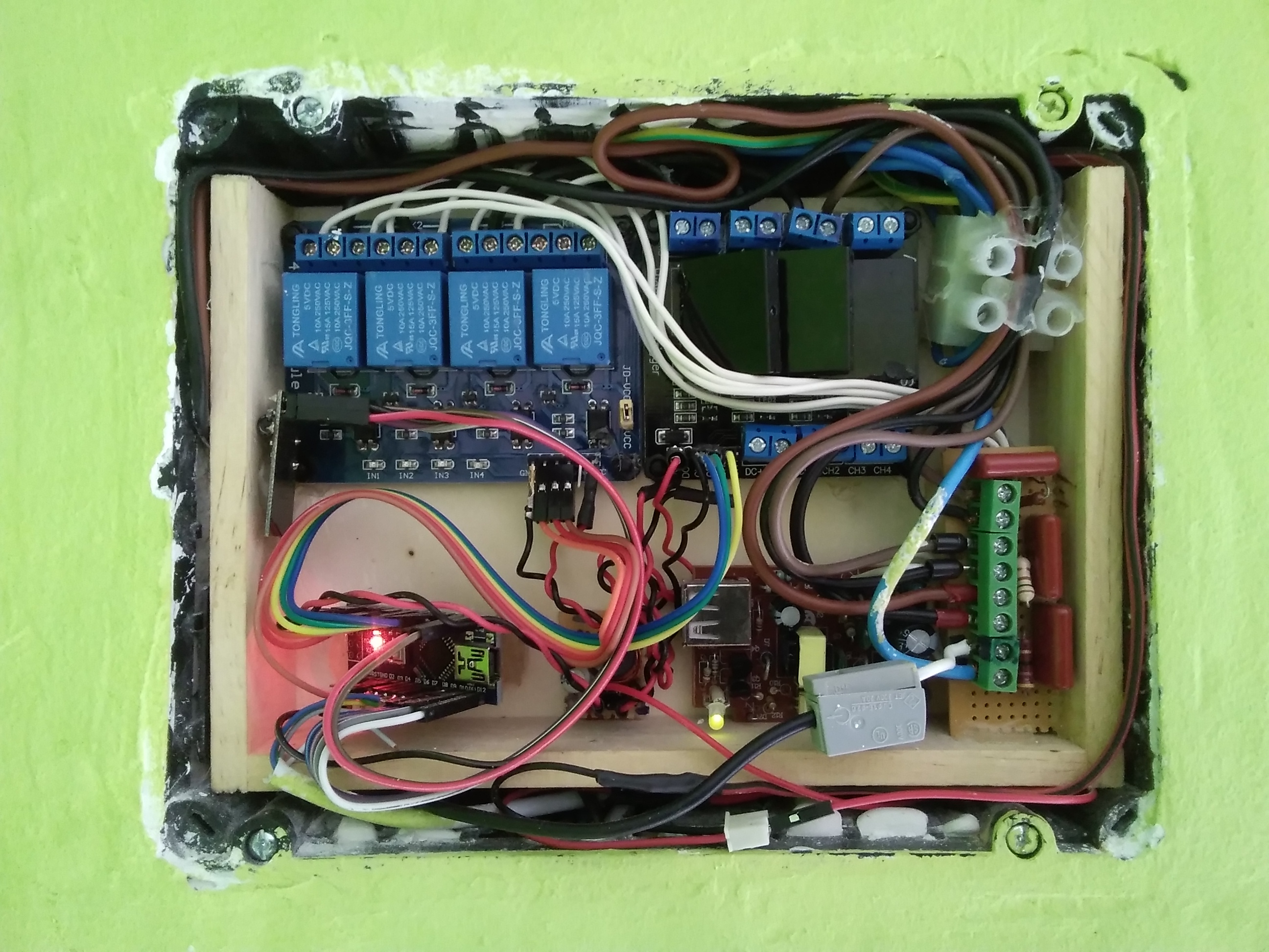
Results and Practical Application
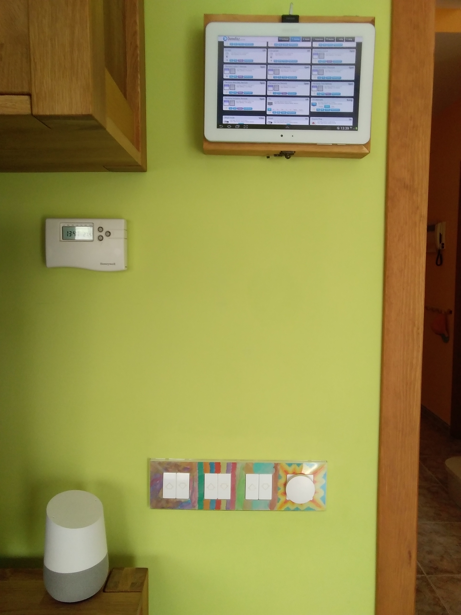
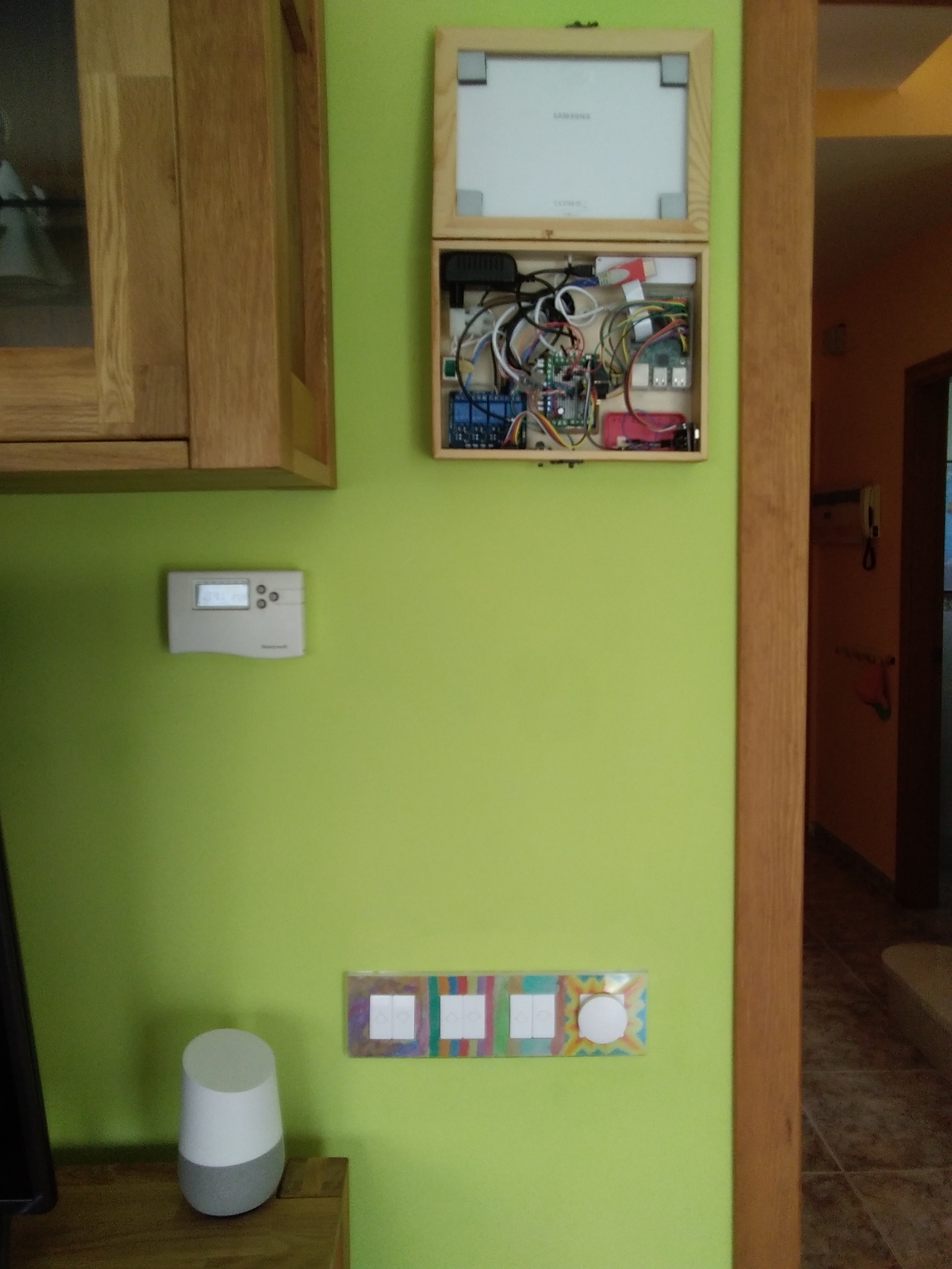
The combination of Arduino, Raspberry Pi, and Google Home allows me to control things in various ways:
- Manual: Press wall switches as usual.
- Tablet: Control via the Domoticz Dashboard screen mounted on the wall.
- Voice Control: Voice commands via Google Assistant, such as "Hey Google, blinds down," using IFTTT to connect Webhooks to Domoticz.
Demonstration Video:
I hope this project will be useful to all fellow engineers and makers.
Sincerely, gomecin
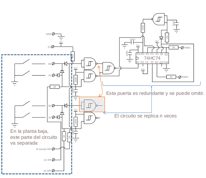
Appendix: For Those Who Don't Want to Use a Microcontroller (Discrete Circuit)
If you don't like programming, or want a basic circuit that works with Passive components, here is a circuit diagram I designed and tested in the early stages. Although it does work, I highly recommend using the Arduino version due to its much higher flexibility and stability.