What is this project about?
This is an in-depth guide on how to modify a classic stereo system that uses a "Rotary Encoder" for volume control, converting it into a Push Button controlled system with Bluetooth support, using a custom-designed control board.
Introduction
This project started with the Panasonic SA-AK45 stereo, a late 90s component stereo system known for its excellent sound quality. However, a common issue was the faulty volume knob, as systems from that era began transitioning from variable resistors (Potentiometers) to Digital Rotary Encoders.
The core of this work is: even though I used the Panasonic as a prototype, the engineering principles can be applied to any stereo system that uses a Rotary Encoder for volume control, simply by making minor software logic adjustments to match the signal pattern of that particular model.
The original Encoder in this Panasonic model was a complex mechanical device, very difficult to find replacement parts for (internal components are tiny and fragile). So, I decided to remove the original mechanism and replace it with an ATtiny85 microcontroller, which is small, inexpensive, and has sufficient resources to simulate the Encoder's Quadrature signals.
For wireless communication, we will use an HC-06 Bluetooth module, which acts as a Slave to receive commands from a smartphone and then relay them to the ATtiny85.
Supplies
- Panasonic SA-AK45 (or any stereo system that uses an Encoder-type volume control)
- ATtiny85 Microcontroller (the core processing unit)
- DIP-8 Socket (for placing the ATtiny85 to facilitate easy programming removal)
- HC-06 Bluetooth Module (or HC-05 can be used interchangeably)
- 2 LEDs (used as status indicators and part of the voltage divider circuit)
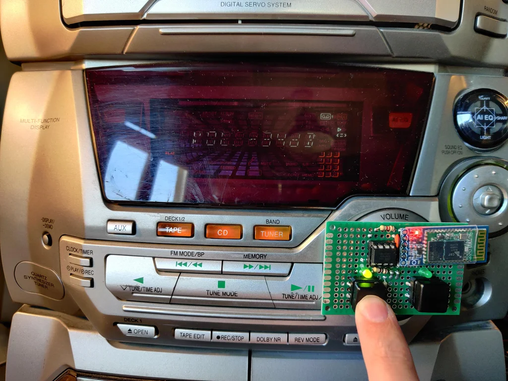
- 2 Tactile Switches (for increasing/decreasing volume)
- Resistors: 100Ω, 1.2kΩ, 2.2kΩ, 100kΩ
- Capacitor: 100 nF (for power supply Decoupling)
- Universal PCB (approximately 4x6 cm)
- AVR Programmer or Arduino Uno (to burn Code onto the ATtiny85)
- Basic tools: Soldering iron, solder, desoldering pump
Step 1: Preparing to Disassemble the Stereo
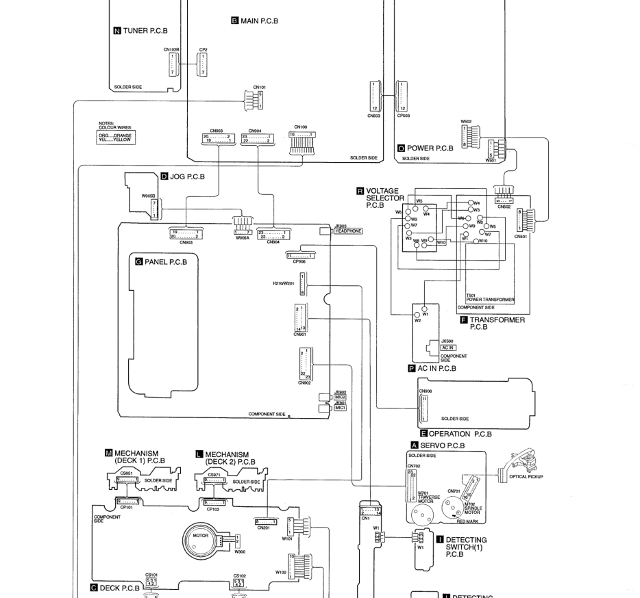
Accessing the Encoder requires caution, as it is installed on the Front Panel circuit board, which often consists of multiple layers. Engineer's Tip: Take photos at every step when disconnecting Ribbon Cables and find the "Service Manual" for that model as a reference. In the case of the SA-AK45, we are heading towards the "E - Operation PCB" board.
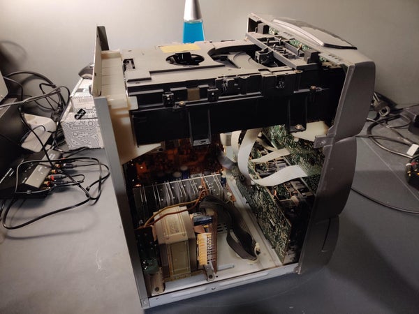
Step 2: Opening the Device
Disconnect all power and signal cables. Unscrew the screws securing the top and side covers (3 on each side) and the back. Note that the cover is held by 3 metal latches to the front panel; gently lift it to release the latches. Then, pull the plastic volume knob straight out.
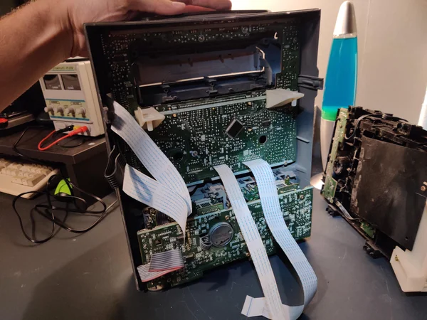
Step 3 - 4: Removing the Front Panel and CD Changer Unit
The front panel connects to the Main PCB via 3 ribbon cables:
- White ribbon cable: Pull straight out from the socket.
- Thick black ribbon cable: You must "lift the locking tabs" on both sides of the connector on the main board before you can pull the cable out.
Additionally, the CD Changer unit, which is mounted on top, must be removed by unscrewing it from the back and disconnecting two more ribbon cables connected to the front panel.
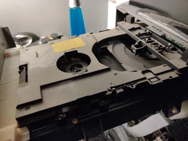
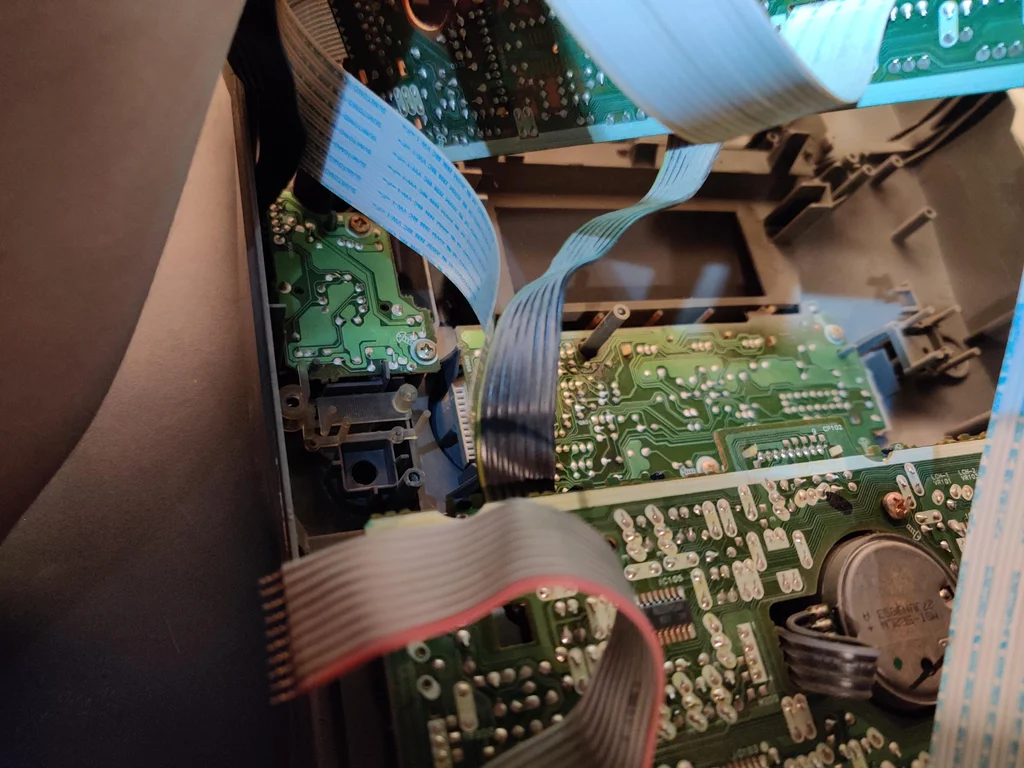
Step 5 - 6: Accessing the Encoder Mounting Point
The Encoder is hidden beneath the Panel PCB (G). We must unscrew all screws and carefully lift the board, as some ribbon cables are still connected to the JOG PCB and Deck PCB. Once lifted, we will see the Operation PCB (E), which houses our target Encoder.
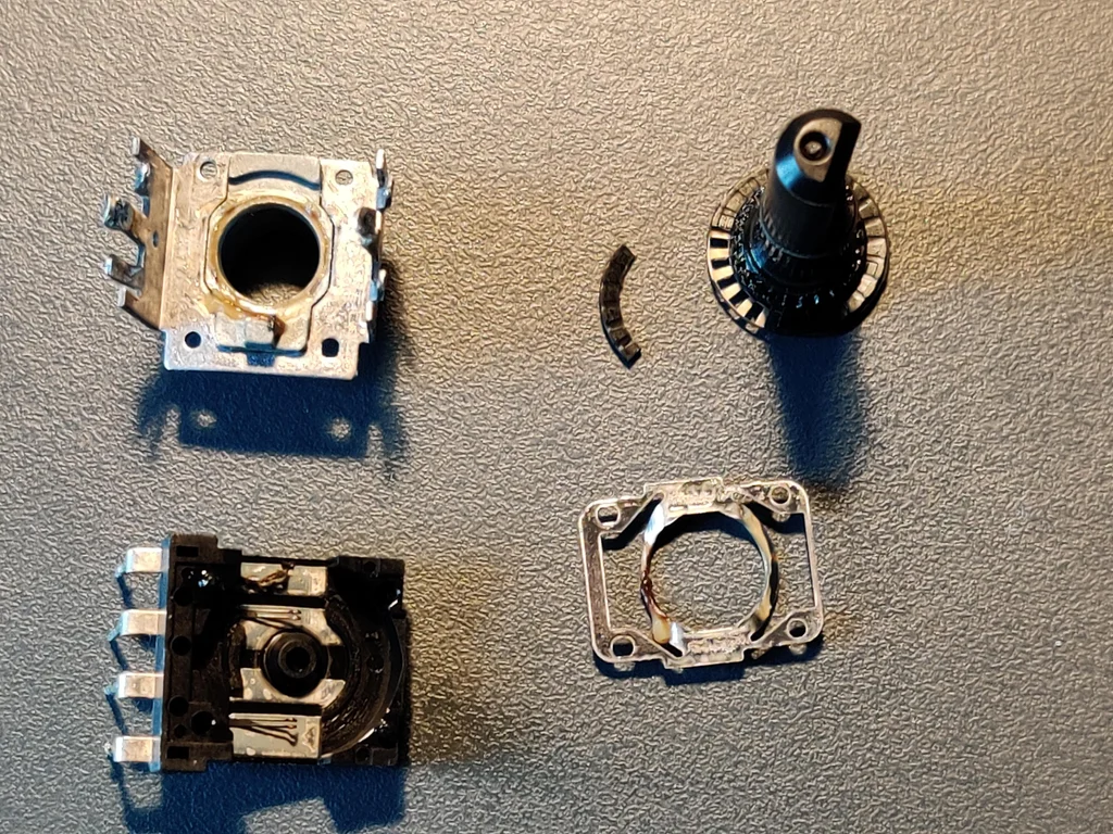
Step 7 - 8: Analyzing the Rotary Encoder Signal
In engineering terms, this type of Incremental Encoder sends signals called "Quadrature Signals" through 3 main pins: A, B, and GND. The operating logic is:
- Clockwise rotation: The signal changes in the sequence A LOW -> B LOW -> Both HIGH
- Counter-clockwise rotation: The signal sequence reverses to B LOW -> A LOW -> Both HIGH
From disassembling and analyzing the original device (which was broken due to fractured plastic contacts), I found that it had a resolution of 24 PPR (Pulses Per Revolution) and no complex signal overlap between A and B, making it easy to simulate these signals using digitalWrite and delay commands in ATtiny85.
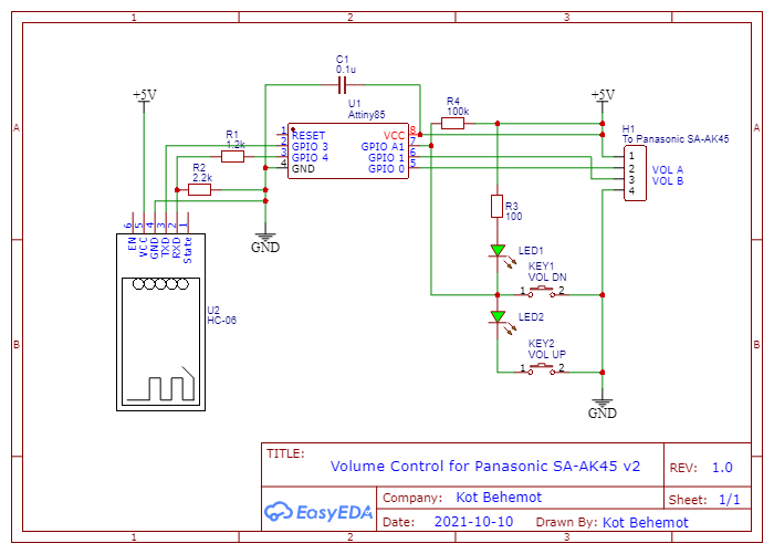
Step 9 - 10: Circuit Design and Control Logic
The challenging problem is that the ATtiny85 has limited I/O pins (5 pins), but we need to use:
- Output signals (A and B) = 2 pins
- Input signals (2 push buttons) = 2 pins
- Bluetooth communication (RX and TX) = 2 pins Totaling 6 pins! Which exceeds the available number.
Solution Technique (Embedded Optimization): We will use only one Analog Input (A1) pin to read the values of 2 push buttons, using the principle of a Voltage Divider.
- No button pressed: Voltage near 5V (Analog value ~1023)
- Decrease volume button pressed: Voltage 0V (shorted to GND, Analog value ~0)
- Increase volume button pressed: Voltage approximately 2.5V (through voltage divider resistors, Analog value ~512)
Bluetooth System Upgrade:
We connect the HC-06 module to pins 3 and 4 using the SoftwareSerial library. Since the HC-06 operates at 3.3V while the ATtiny85 operates at 5V, we must use 1.2kΩ and 2.2kΩ resistors as a voltage divider circuit to reduce the voltage at the HC-06's Rx pin, preventing module damage.
Step 11 - 12: Programming the ATtiny85 and Preparing Connection Points
You must use an Arduino Uno in "Arduino as ISP" mode to burn Code onto the ATtiny85, using the board settings for ATtiny85, Internal Clock 1MHz (or 8MHz as appropriate).
Code Logic Analysis:
In the volUp() and volDown() functions, we will simulate the actual Encoder rotation:
void volUp() {
  digitalWrite(VOL_A, LOW); // Pin A touches GND first
  delay(80);
  digitalWrite(VOL_A, HIGH);
  digitalWrite(VOL_B, LOW); // Pin B touches GND next
  delay(80);
  digitalWrite(VOL_B, HIGH);
  delay(80);
}
The SIGNAL_DELAY value of 80ms was determined experimentally to ensure the stereo responds to button presses promptly and not too fast, causing it to skip steps.
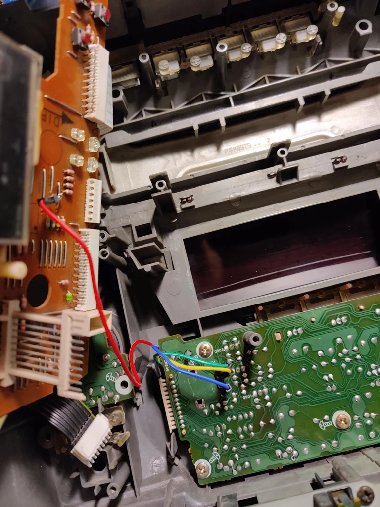
For connecting to the stereo, I soldered 4 Jumper wires to the original Encoder points (A, B, GND) and found a 5V power supply point from the Panel PCB to power our new circuit.